manuals.online logo
Brands
  1. Home
  2. •
  3. Brands
  4. •
  5. Honeywell
  6. •
  7. Accessories
  8. •
  9. Honeywell CTS-V Series User manual

Honeywell CTS-V Series User manual

This manual suits for next models

5

Other Honeywell Accessories manuals

Honeywell DCP917 Series User manual

Honeywell

Honeywell DCP917 Series User manual

Honeywell NOTIFIER SMART 2 NFX-SMT2 User manual

Honeywell

Honeywell NOTIFIER SMART 2 NFX-SMT2 User manual

Honeywell FSA Series User manual

Honeywell

Honeywell FSA Series User manual

Honeywell UV100RM TrueUV Operation manual

Honeywell

Honeywell UV100RM TrueUV Operation manual

Honeywell DO8EZS User manual

Honeywell

Honeywell DO8EZS User manual

Honeywell RCW101N User manual

Honeywell

Honeywell RCW101N User manual

Honeywell RDWL515P2000 Operating instructions

Honeywell

Honeywell RDWL515P2000 Operating instructions

Honeywell 705 Series User manual

Honeywell

Honeywell 705 Series User manual

Honeywell S301M Manual

Honeywell

Honeywell S301M Manual

Honeywell DT7550UK2 DUAL TEC User manual

Honeywell

Honeywell DT7550UK2 DUAL TEC User manual

Honeywell H7012A User manual

Honeywell

Honeywell H7012A User manual

Honeywell RDWL313A2000 Operating instructions

Honeywell

Honeywell RDWL313A2000 Operating instructions

Honeywell DirectLine DL422 User manual

Honeywell

Honeywell DirectLine DL422 User manual

Honeywell DO8EZS User manual

Honeywell

Honeywell DO8EZS User manual

Honeywell 203365A User manual

Honeywell

Honeywell 203365A User manual

Honeywell SK-FIRE-CO-W User manual

Honeywell

Honeywell SK-FIRE-CO-W User manual

Honeywell K594.RF User manual

Honeywell

Honeywell K594.RF User manual

Honeywell IS3016A User manual

Honeywell

Honeywell IS3016A User manual

Honeywell TruStability TSC Series User manual

Honeywell

Honeywell TruStability TSC Series User manual

Honeywell DUAL TEC DT8320AF4 User manual

Honeywell

Honeywell DUAL TEC DT8320AF4 User manual

Honeywell One Wireless WCX Series User manual

Honeywell

Honeywell One Wireless WCX Series User manual

Honeywell IntelliSense DT-640STC Quick start guide

Honeywell

Honeywell IntelliSense DT-640STC Quick start guide

Honeywell DC915 series User manual

Honeywell

Honeywell DC915 series User manual

Honeywell DC915 series Operating instructions

Honeywell

Honeywell DC915 series Operating instructions

Popular Accessories manuals by other brands

Quincy lab 140AE-1 operating manual

Quincy lab

Quincy lab 140AE-1 operating manual

HomePro ZIR000 user manual

HomePro

HomePro ZIR000 user manual

DOL 20SCR Technical user guide

DOL

DOL 20SCR Technical user guide

RAB Smart Task installation manual

RAB

RAB Smart Task installation manual

Kemppi KMS 300 quick guide

Kemppi

Kemppi KMS 300 quick guide

Stearns 57,500 Series Installation and service instructions

Stearns

Stearns 57,500 Series Installation and service instructions

iGuzzini TWILIGHT COPENAGHEN manual

iGuzzini

iGuzzini TWILIGHT COPENAGHEN manual

Adelaide Annexe & Canvas Avan Deluxe installation guide

Adelaide Annexe & Canvas

Adelaide Annexe & Canvas Avan Deluxe installation guide

OHAUS 5000 instruction manual

OHAUS

OHAUS 5000 instruction manual

HOME8 WLS1300 quick start guide

HOME8

HOME8 WLS1300 quick start guide

MAXBOTIX MaxSonar quick start guide

MAXBOTIX

MAXBOTIX MaxSonar quick start guide

ioSmart iSmart56 Installation and user guide

ioSmart

ioSmart iSmart56 Installation and user guide

Focusrite Scarlett 18i8 user guide

Focusrite

Focusrite Scarlett 18i8 user guide

Velleman ED38105 user manual

Velleman

Velleman ED38105 user manual

JumpSport SkyBounce user manual

JumpSport

JumpSport SkyBounce user manual

Prima-Temp PRIYA Instructions for use

Prima-Temp

Prima-Temp PRIYA Instructions for use

Tefcold BC85I-BC85I W user manual

Tefcold

Tefcold BC85I-BC85I W user manual

Vaisala WMS302 user guide

Vaisala

Vaisala WMS302 user guide

manuals.online logo
manuals.online logoBrands
  • About & Mission
  • Contact us
  • Privacy Policy
  • Terms and Conditions

Copyright 2025 Manuals.Online. All Rights Reserved.

INSTALLATION INSTRUCTIONS
31-00144-02
20
Solid and Split Core 0-5/10Vdc
Output Current Sensors
CTS-V AND CTP-V SERIES
APPLICATION
The 0-5/10Vdc Output Solid and Split Core Current
Sensors are designed for use in any AC current
monitoring application in which you are looking to
monitor a particular piece of equipment.
SPECIFICATIONS
Monitored Current Type: AC Current
Maximum AC Voltage: 600 VAC
Isolation Voltage: 2200 VAC
Supply Voltage:
Induced from the Monitored Conductor (Insulated
Conductors only)
150-Amp Sensors: 0 to 10 VDC
Operating Temperature Range: 5 to 104ºF (-15 to
40ºC)
Operating Humidity Range: 0 to 95%, non-con-
densing
Storage Temperature: 41 to 95°F (5 to 35°C)
RH Range: 40% to 85% RH, non-condensing
Wire Recommendations: 2 Conductor (Shielded
Cable)
Wire Size:
18 to 24 AWG (0.823 mm2to 0.205 mm) Copper
Wires only
Terminal Block Torque Rating: 4.43 to 5.31 in-lbs.
(0.5 to 0.6 Nm)
Minimum Mounting Distance:
1” (2.6 cm) between current sensor & other magnetic
devices (Relays, Contactors, Transformers)
Agency Approvals:
UL/CUL US Listed (UL 508) Ind. Control Equipment
(File # E309723), CE, RoHS2, WEEE
STANDARD ORDERING
Table 1. Standard Ordering.
WARNING
This product is not intended to be used for
Life or Safety applications.
This product is not intended for use in any
hazardous or classified locations. The CTS-V
and CTP-V Series Current Sensors must be
used on Insulated Conductors Only!
WARNING
Electrical shock hazard.
Disconnect and lock out all power sources
before installation as severe injury or death
may result from electrical shock due to
contact with high voltage wires.
Model # Selectable Ranges Measurement AC Waveform Solid-Core Split-Core
Output
Signal
CTS-V-50 0 to 10/20/50A Average Pure Sinusoidal • 0 to 5 VDC
CTS-V-150 0 to 50/100/150 Average Pure Sinusoidal • 0 to 10 VDC
CTP-V-50 0 to 10/20/50A Average Pure Sinusoidal • 0 to 10 VDC
CTP-V-150 0 to 50/100/150 Average Pure Sinusoidal • 0 to 10 VDC
SOLID AND SPLIT CORE 0-5/10VDC OUTPUT CURRENT SENSORS
31-00144—02 2
INSTALLATION
Make sure that all installations are in compliance with
all national and local electrical codes. Only qualified
individuals that are familiar with codes, standards,
and proper safety procedures for high-voltage
installations should attempt installation. The current
sensor will not require external power, since the power
for the current sensor is induced from the conductor
being monitored.
The current sensor may be mounted in any position
using the two #8 x ¾” Tek screws and the mounting
holes in the base, or snapped directly on to the 35mm
DIN rail (See Fig. 1). Leave a minimum distance of 1”
(3 cm) between the current sensor and any other
magnetic devices such as contactors and
transformers.
Fig. 1. Sensor Placed on Rail.
Latch Operation for CTP-V Series
Press down on the side tab and swing the top of the
unit up to open the split core current sensor as shown
in Figure 2. Press down firmly on the cover to close the
current sensor. An audible “click” will be heard as the
tab slides over the tongue on the base.
CAUTION
Mating surfaces of the magnetic core are
exposed when the sensor is open.
Electrical contact grease, present on the cores
to prevent corrosion, can capture grit and dirt if
care is not exercised. Operation can be
impaired if anything prevents good contact
between pole pieces. Visually check the mating
parts of the core before closing the current
sensor.
Fig. 2. Opening CTP-V Series.
Current Sensor Setup
The amperage range selected represents the
maximum current that can be applied to the
conductor being monitored, Do not exceed! All current
sensors with selectable ranges will have the range
selection jumper factory set on the high range. For
models with field selectable amperage ranges, select
the correct amperage range using the range selection
jumper.
WIRING
We recommend the use of a two conductor 16 to 22
AWG shielded cable, copper wire only, for all Analog
current sensor installations. A maximum wire length
of less than 30 meters (98.4 feet) should be used
between the current sensors and the Building
Management System or controller.
M37377
+
–
M37359
SOLID AND SPLIT CORE 0-5/10VDC OUTPUT CURRENT SENSORS
331-00144—02
NOTE: When using a shielded cable, be sure to con-
nect only (1) end of the shield to ground at the
controller. Connecting both ends of the shield
to ground may cause a ground loop.
When removing the shield from the sensor end, make
sure to properly trim the shield to prevent any chance
of shorting. The current sensor terminals are polarity
sensitive and represent a linear 0 to 5 or 0 to 10 VDC
output signal. Tighten the screws at the terminal block
connections to the recommended torque of 0.5 to 0.6
Nm (4.43 to 5.31 in-lbs.). The aperture (hole) size of
the current sensor is 0.75” (1.90 cm).
Wiring Example
Fig. 3. Analog Circuit.
TROUBLESHOOTING
Current Conversion Formulas
To convert the current sensor output signal to a current reading.
4-20mA output to Current reading (4mA = 0 Amps and 20mA)
Example: 12mA current sensor output signal
Total Span = 250 Amps
Multiplier = 20mA-4mA/Total Span = 0.064
(12mA-4mA)/0.064= 125 Amps
WEEE Directive
At the end of their useful life the packaging and product should be disposed of via a suitable recycling center. Do
not dispose of with household waste. Do not burn.
M37360
SHIELDED CABLE
(–) SIGNAL COMMON
+0-5 0-10 VDC
ANALOG INPUT
GND (SHIELD)
PLC, DDC OR DATA
ACQUISITION SYSTEMS
Problem Solution
No reading •Verify that there is current flowing through the conductor being monitored
with a clamp-on current probe. The power for the current sensor is induced
from the conductor being monitored.
•Check the polarity of the circuit.
•Verify that the terminals are screwed down, wires are firmly in place.
•Disconnect the wires from the current sensor output. Measure the voltage
across the current sensor output with a Voltmeter to verify that the sensor
is working properly.
Erratic readings •Verify that the wires are terminated properly.
•In areas of high RF interference, shielded cable may be necessary to
stabilize signal.
Inaccurate readings •If you suspect that the current sensor is not reading within the accuracy
specifications, please contact the factory for assistance.
Current Sensor is operating at a
low-level current or failing to
operate within the accuracy
specifications.
•Visually check the mating parts of the core to ensure there is no debris
between the split contacts. See Figure 2.
•Remove all debris or dust manually and close the current sensor.
•Continue to retest the sensor in your application.
SOLID AND SPLIT CORE 0-5/10VDC OUTPUT CURRENT SENSORS
Home and Building Technologies
In the U.S.:
Honeywell
715 Peachtree Street NE
Atlanta, GA 30308
customer.honeywell.com
® U.S. Registered Trademark
© 2018 Honeywell International Inc.
31-00144—02 M.S. Rev. 05-18
Printed in United States
By using this Honeywell literature, you agree that Honeywell will have no liability for any damages arising out of
your use or modification to, the literature. You will defend and indemnify Honeywell, its affiliates and subsidiaries,
from and against any liability, cost, or damages, including attorneys’ fees, arising out of, or resulting from, any
modification to the literature by you.
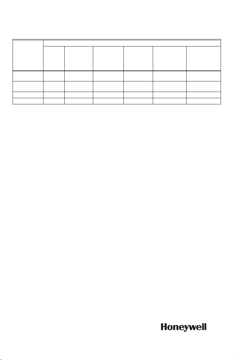
CHINA ROHS COMPLIANCE INFORMATION
ENVIRONMENT-FRIENDLY USE PERIOD (EFUP) TABLE
󴉆󸀮󴏵󱡽󳮹 SJ/T 11364 󵵙󸊿󲷢󶴹󱳷
O: 󸀮󶆺󸛋󴈄󲸓󵙀󸢹󲔩󸛋󸽩󱝾󳧟󴈄󲕓󸢹󴉿󳾒󱙆󵵙󲀯󹄡󲕓󲔩 GB/T 26572 󸊿󲷢󵵙󹢔󹄡󸉔󴭁󱝥󱘕
X: 󸀮󶆺󸛋󴈄󲸓󵙀󸢹󷋼󲻒󲔩󸛋󸽩󱝾󵵙󴍅󱘈󲕓󸢹󴉿󳾒󱙆󵵙󲀯󹄡󸤥󱲡 GB/T 26572 󸊿󲷢󵵙󹢔󹄡󸉔󴭁
This table is prepared in accordance with the provisions of SJ/T 11364.
O: Indicates that said hazardous substance contained in all of the homogeneous materials for this part is below
the limit requirement of GB/T 26572.
X: Indicates that said hazardous substance contained in all of the homogeneous materials for this part is above
the limit requirement of GB/T 26572.
󴉃󱳊󱮧󸀮󱯜󵵙󱯇󱝎󸽩󱝾󽘜󵵜󱘗󲀯󱞄󱠇󸤥󱲡󹢔󹄡󸉔󴭁󵵙󹢔󱳷󱡋󵫞󵙀󸢹
All other components, not listed in the table, do not contain restricted substances above the threshold level.
REGULATORY INFORMATION
FCC REGULATIONS: § 15.19 (A)(3)
This device complies with part 15 of the FCC Rules.
Operation is subject to the following two conditions:
1. This device may not cause harmful interference,
and
2. This device must accept any interference
received, including interference that may cause
undesired operation.
IC REGULATIONS: RSS-GEN
This device complies with Industry Canada’s license-
exempt RSSs.
Operation is subject to the following two conditions:
1. This device may not cause interference; and
2. This device must accept any interference,
including interference that may cause unde-
sired operation of the device.
Le présent appareil est conforme aux CNR d’Industrie
Canada applicables aux appareils radio exempts de
licence. L’exploitation est autorisée aux deux
conditions suivantes :
1. l’appareil ne doit pas produire de brouillage;
2. l’utilisateur de l’appareil doit accepter tout
brouillage radioélectrique subi, même si le
brouillage est susceptible d’en compromettre le
fonctionnement.
FCC WARNING (PART 15.21) (USA ONLY)
Changes or modifications not expressly approved by
the party responsible for compliance could void the
user’s authority to operate the equipment.
󸽩󱝾󱿽󶌇
Component
Name
󴈄󲸓󵙀󸢹 - Hazardous Substances
󹚮(Pb)
Lead (Pb)
󴭰(Hg)
Mercury (Hg)
󹜲(Cd)
Cadmium (Cd)
󱮺󱞀󹛕 (Cr6+)
Chromium VI
Compounds
(Cr6+)
󲡕󴼤󶾌󷔦 (PBB)
Polybrominate
d Biphenyls
(PBB)
󲡕󴼤󱛔󷔦󹂮
(PBDE)
Polybrominated
Diphenyl Ethers
(PBDE)
Assorted
capacitors
OO O O O O
Assorted
resistors
OO O O O O
Core O O O O O O
Screw O O O O O O