manuals.online logo
Brands
  1. Home
  2. •
  3. Brands
  4. •
  5. Honeywell
  6. •
  7. Accessories
  8. •
  9. Honeywell IS3016A User manual

Honeywell IS3016A User manual

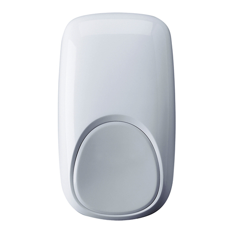
IS3016A Passive Infrared Motion Sensor with Anti-Mask - Installation Instructions
1
2.1 - 2.7 m
(6' 9" - 8' 9")
30 cm
(12")
*
* Keep Clear / Keep Clear / Keep Clear /
Keep Clear / Keep Clear / Keep Clear
*
2.3 m
(7' 6")
EMPLACEMENT / LOCALIZACIÓN / MONTAGEORT / LOCATION /
POSIZIONAMENTO / LOCATION
2
3
1
2
UNLOCK, PRESS AND OPEN /
UNLOCK, PRESS AND OPEN
3INSTALLATION / MONTAJE / MONTAGE / MOUNT / MONTAGGIO / MOUNT
- DOIT être installée sur un montant de cloison, une surface de
bois solide ou à l'aide d'un ancrage de gypse robuste.
- DEBE montarse en un travesaño, madera sólida o con un
soporte para pared resistente.
- MUST be
mounted to a stud, solid wood, or with a robust
wall anchor.
- MUST be
mounted to a stud, solid wood, or with a robust
wall anchor.
- MUST be
mounted to a stud, solid wood, or with a robust
wall anchor.
- MUST be
mounted to a stud, solid wood, or with a robust
wall anchor.
3.5 mm x 30 mm
(#6 x 1 1/4")
3.5 mm
(#6)
AA
A
A
BB B
B B
B B
*Not Included / Not Included / Not Included
Not Included / Not Included / Not Included
*
*
4COMPOSANTS ET REGLAGES / COMPONENTES Y CONFIGURACIÓN / KOMPONENTEN UND EINSTELLUNGEN /
COMPONENTS AND SETTINGS / COMPONENTI E IMPOSTAZIONI / COMPONENTS AND SETTINGS
IS3000
AM LED1 2.2 2.2 34.7 5.6 1 2.2 4.7 5.6
EOL
KOhm
PULL
TO DISABLE
LOOK DOWN
LOOK DOWN
W1
*Activé
*Habilitado
*Aktiviert
*ingeschakeld
*Abilitado
*Enabled
Désactivé
Deshabilitado
Deaktiviert
uitgeschakeld
Disabilitado
Disabled
* Réglage usine /
defecto de fábrica /
factory default /
Werkseinstellung /
difetto della fabbrica /
factory default
*
Réglage des résistances (EOL) / Ajustes de RFL /
EOL Einstellungen / EOL Settings /
Regolazioni de EOL / EOL Settings
* * *
ALARME
ALARMA
ALARM
ALARM
ALLARME
ALARM
AUTOPROTECTION
TAMPER
SABOTAGE
TAMPER
TAMPER
TAMPER
ANTI-MASQUE
ANTIENMASCARAMIENTO
ABDECKÜBERWACHUNG
ANIT-BLOKKERING
ANTIMASCHERAMENTO
ANTI-MASK
EOL
KOhm
ON
ON
OFF
W1 W1
1 boucle
1 bucle
1 loop
1 Zone konfiguriert
1 loop
1 loop
2 boucles
2 bucles
2 loops
2 Zonen konfiguriert
2 loop
2 loops
*
Anti-masque
Antienmascaramiento
Abdecküberwachung
Anit-blokkering
Antimascheramento
Anti-mask
12.2 2.2 3
4.7 5.6 12.2 4.7 5.6
LED
- 2 -
CÂBLAGE / CABLEADO / ANSCHLUSS / WIRE / COLLEGAMENTO / WIRE
Détails de câblage page 3
Detalles del cableado en la página 4
Verdrahtungs-Details siehe Seite 5
Wiring Details on Page 6
Particolari dei collegamenti alla pagina 7
Wiring Details on Page 8
Autoprotection
Tamper
Sabotage
Sabotage
Tamper
Tamper
30 mA
25 Vcc/VDC
Défaut
Fallo
Störung
Störung
Guasto
Fault
30 mA
25 Vcc/VDC
Alimentation
Alimentación
Betriebsspannung
Spannungsversorgung
Alimentazione
Power
16 mA
9 - 15 Vcc/VDC
Alarme
Alarma
Alarm
Alarm
Allarme
Alarm
30 mA
25 Vcc/VDC
LED TBL T C V-V+
T NCTBL
5
LED
0 VDC - Vsupply
1.8 mA max
0.2-0.52mm2
(24-20 AWG)
2
1
2
6TEST DE DÉTECTION / TEST DE PASEO / FUNKTIONSTEST / LOOPTEST / TEST DI COPERTURA / WALK TEST
20 sec
30
0
45
20
10
ON
OFF
LED
7COUVERTURE DE DETECTION / PATRON DE DETECCIÓN / ERFASSUNGSBEREICHE / DETECTIEPATRONEN /
DIAGRAMMA DI COPERTURA / DETECTION PATTERNS
Vue de dessus
Vista Desde Arriba
Draufsicht
Bovenaanzicht
Vista in pianta
Top View
Vue de coté
Vista Lateral
Seitenansicht
Zijaanzicht
Vista in sezione
Side View
0
0.5
1.85
2.3m
PLAN VIEW
ALL ZONES
7’
2 m
0
0
13’
4 m 20’
6 m 7’
8 m 33’
10 m 40’
12 m
7’
2 m
13’
4 m
20’
6 m
7’
8 m
33’
10 m
40’
12 m
7’
2 m
13’
4 m
20’
6 m
7’
8 m
33’
10 m
40’
12 m 46’
14 m 53’
16 m
7’
2 m
0
13’
4 m 20’
6 m 7’
8 m 33’
10 m 40’
12 m 46’
14 m 53’
16 m
A B C D
LED Power
p Walk Test Normal Fault Anti-Mask
Red Slow
Blink
ON
Alarm
ON
Alarm
Fast
Blink OFF
Yellow OFF OFF OFF OFF Fast
Blink
Zones / Zonas / Erfassungsbereiche /
Zones / Zones / Zones
A
2
Basses / Ángulo 0 /
Draufsichtbereich / Onder Kruip /
Antistrisciamento / Look-down
B
12
Courtes / Corto / Nahbereich /
Laag / Inferiori / Lower
C
10
Intermédiaires / Intermedias /
Mittelbereich / Midden /
Intermedie / Intermediate
D
36
Longues / Largo / Fernbereich
/ Lang / Lunga portata / Long
IS3016A English
- 8 -
COMMONZ1
Panel
PIR Sensor
V+V-NCTTBLTBL
TAMPER ALARM
FAULT
RF
W1
RA
RT
REMOTE LED CONTROL
CTLED
Panel
PIR Sensor
V+V-NC
TTBLTBL
TAMPER ALARM
FAULT
RF
W1
RA
RT
REMOTE LED CONTROL
CTLED
CZ1 Z2
W1
W1
ON
OFF
LED
IR
Window
WIRING DETAILS
-Observe proper polarity.
-If not using the integrated EOL resistors, set all switches to off.
-If using the integrated EOL resistors:
1. Connect the sensor to the panel (see wiring diagrams below).
2. Set the appropriate tamper, alarm and anti-mask DIP switches to
ON (see Step 4 on page 1).
Notes:
-Consult the Control Panel manual to determine proper EOL selection.
-The tamper, alarm and anti-mask EOL settings must each only have one
switch ON.
-The EOL values should be set at the same time.
Fault, Alarm
and Tamper
configured to
one loop.
Fault, Alarm
and Tamper
configured to
two loops.
RA = Alarm EOL resistor
RT = Tamper EOL resistor
RF = Anti-Mask EOL resistor
W1 = 1 and 2 loop connection resistor.
WALK TESTING
Refer to Step 6 on page 2.
1. Close the sensor and apply power to the sensor. Initialization is
complete when the LED stops flashing slowly (about 20 seconds).
2. Walk through the detection area and observe the LED.
LED
INDICATIONS
LED Power
p Walk Test Normal Fault Anti-Mask
Red Slow
Blink
ON
Alarm
ON
Alarm
Fast
Blink OFF
Yellow OFF OFF OFF OFF Fast
Blink
Walk test mode is active for 10 minutes, then automatically exits test
mode, disables the LED and enters normal operation mode. For an
additional 10 minute walk test, enable Walk Test mode again with the
Flashlight feature:
Note: In Walk Test mode the LED is active regardless of the LED
Enable/Disable Dip switch setting.
Flashlight Feature:
1. Use a flashlight with a bright light beam, and
stand within 4’ (1.2 m) of the sensor.
2. Swing past the light beam across the sensor IR
window 3-5 times, holding the beam on the lens
for 0.5 second each pass.
The flashlight feature is only available for the first 24 hours after
installation.
REMOTE LED ENABLE (LED INPUT)
The LED input terminal allows the LED to be
remotely enabled. To use this feature, the LED
DIP switch (switch 2) must be OFF, allowing
the LED to operate based on the voltage level
connected to the LED Input (see Wiring Details).
Switch 2 LED Input LED Operation
OFF High ( +12 V) Enabled
OFF Low (0 V) Disabled
ON Low (0 V) or High (+12 V) Enabled
RELAY OPERATION
SENSOR STATUS
Normal Intrusion Fault
1
Mask
2
Alarm Relay Closed Open Closed Open
Fault Relay
3
Closed Closed Open Open
1
For information on Fault conditions, see the Troubleshooting section.
2
In a Mask condition, the Alarm and Fault relays will activate simultaneously, and remain
open until the condition has been cleared.
3
In a Fault condition, the Fault relay will latch open until the Fault condition has been cleared.
MASK CONDITION
Normal Anti-Mask Condition
The sensor signals a mask condition when a variety of materials and reflective
objects are placed within 50mm in front of the sensor. To avoid false mask
alarms, follow the mounting guidelines shown in Step 1.
Clearing an Anti-Mask Condition
When most masking materials or objects are removed, the anti-mask condition
will be cleared after several seconds. When the cause of the anti-mask condition
is any type of spray or paint coating applied to the IR window, the window must
be replaced before the anti-mask condition can be cleared. After replacing the
window, perform a walk-test on the sensor.
TROUBLESHOOTING
FAULT*
NORMAL MASK Low Voltage
1
Fault
2
Alarm Relay Closed Open Closed Closed
Fault Relay Closed Open Open Open
Red LED Off Off Off Flashing
*FAULT CONDITIONS:
1Low Voltage: The sensor is disabled.
2Two possible conditions:
• PIR self-test failure: The sensor is disabled.
• Temperature compensation failure: The temperature compensation is
disabled.
Depending on the Fault condition, take the following corrective actions:
• Verify the power supply is sufficient.
• Cycle power to the sensor.
• Walk test the sensor.
• Verify the sensor is not blocked or masked.
If the Fault condition does not clear, replace the sensor.
Approval Listings:
PD6662:2010
IMQ
NF&A2P
T014
C-Tick
EN50131-2-2, Security Grade 3, Environmental Class II.
Suitable for connection to an EN 60950 Class II Limited Power Source.
Note: In EN 50131-2-2 compliant installations, mount the sensor
at 2.3m, enable Look-Down and lock the sensor housing with the
cover lock.
LED
ON
OFF
- 9 -
CARACTERISTIQUES ESPICIFICACIONES TECHNISCHE DATEN SPECIFICATIES SPECIFICHE TECNICHE SPECIFICATIONS
Portée : 16 m x 22 m Alcance: 16 m x 22 m Erfassungsbereich:
16 m x 22 m
Bereik: 16 m x 22 m Portata: 16 m x 22 m Range: 16 m x 22 m
Alimentation :9.0 - 15
Vcc; 15 mA typique,
16 mA maximum, 12 Vcc;
Ondulation résiduelle max.
3 V crête à crête sous
12 Vcc
Alimentación: 9.0 - 15.0
VCC; 15 mA típico; 16 mA
máximo, 12 VCC; Rizado CA:
3 V pico a pico a 12 VCC
nominal
Energieversorgung: 9,0 -
15,0 VDC; 15 mA (typ.); max.
16 mA;
AC-Welligkeit: 3 V Spitze-
Spitze bei einer
Nennspannung von 12 V DC
Voeding:
9.0 - 15.0 VDC ; 15 mA nominaal
bij 12 VDC, 16 mA max;
AC Rimpel: 3 V piek-piek bij
nominaal 12 VDC
Alimentazione: 9.0 - 15.0
VDC; 15 mA tipico; 16 mA
massimo, 12 V —; Ripple
AC: 3 V picco-picco a 12
nominali
Power: 9.0 - 15 VDC; 15
mA typical, 16 mA
maximum, 12 VDC; AC
Ripple: 3 V peak-to-peak
at nominal 12 VDC
Relais d’alarme :
Normalement fermé ; 30
mA, 25 Vcc, 22 Ohms de
résistance max; Durée
d’ouverture du relais: 3
sec.
Relé de Alarma: Energizado
Forma A; 30 mA, 25 VCC;
resistencia 22 Ohms máximo;
Duración del Relé de Alarma: 3
segundos
Alarmrelais: Aktiviertes
Form-A-Relais; 30 mA, 25
VDC; Widerstand max. 22
Ohm, Alarmrelais-
Anzugsdauer: 3s
Alarm Relais:Energized Form
A; 30 mA, 25 VDC, 22 Ohms
resistance maximum. Alarm
Relay Duration: 3 seconds
Relè di Allarme:
Energizzato Form A; 30 mA,
25 V —; resistenza massimo
da 22W; Durata del Relè di
Allarme: 3 secondi
Alarm Relay: Energized
Form A; 30 mA, 25 VDC,
22 Ohms resistance
maximum. Alarm Relay
Duration: 3 seconds
Relais de défaut
:
Normalement fermé ; 30
mA, 25 Vcc; 22 Ohms de
résistance max
Relé de Fallo: Sin energizar
Forma B; (NC) 30 mA, 25
VCC; resistencia 22 Ohms
máximo
Störungsrelais:
Deaktiviertes Form-B-Relais;
(NC) 30 mA, 25 VDC;
Widerstand max. 22 Ohm
Anti-Mask Relay: Energized
Form B; (NC) 30 ma, 25 VDC;
22 Ohms resistance maximum
Relè di Guasto: Energizzato
Form B; (NC) 30 mA, 25 V —;
resistenza massimo da 22W
Anti-Mask Relay:
Energized Form B; (NC)
30 ma, 25 VDC; 22 Ohms
resistance maximum
Autoprotections :
Ouverture et arrachement
: (normalement fermé
avec capot installé)
30 mA, 25 Vcc
Interruptor Tamper: Cubierta
y Pared: Forma A
(normalmente cerrado con
cubierta instalada); 30 mA,
25 VCC
Sabotagekontakt:
Abdeckung und Wandabriss:
Form A (üblicherweise durch
montierte Abdeckung
geschlossen); 30 mA, 25 VDC
Sabotageschakelaar: Cover &
Wall; (NC with cover installed)
Form A; 30 mA, 25 VDC
Tamper: Coperchio e
parete: modulo A
(generalmente chiuso
con coperchio installato);
30 mA, 25 V —
Tampers: Cover & Wall;
(NC with cover installed)
Form A; 30 mA, 25 VDC
RFI Immunity:
15 V/m, 80 MHz – 2.7
GHz
RFI Immunity:
15 V/m, 80 MHz – 2.7 GHz
RFI Immunity:
15 V/m, 80 MHz – 2.7 GHz
RFI Immuniteit:
15 V/m, 80 MHz – 2.7 GHz
RFI Immunity:
15 V/m, 80 MHz – 2.7 GHz
RFI Immunity:
15 V/m, 80 MHz – 2.7
GHz
Immunité à la lumière
blanche (IRP) : 10,000
Lux typique
Inmunidad del PIR a la luz
blanca: 10,000 Lux típico
PIR-Weißlicht-
Störfestigkeit: 10,000 Lux
(typ.)
PIR Witlicht immuniteit:
10,000 Lux typical
Immunità PIR alla luce
bianca: 10,000 Lux tipica
PIR White Light
Immunity:
10,000 Lux typical
Température de
fonctionnement :
-10°à 55°C
Temperatura de
Funcionamiento:
-10°to 55°C
Betriebstemperaturbereich:
-10°bis 55°C
Werkingstemperatuur:
-10°to 55°C
Temperatura di esercizio:
-10°to 55°C
Operating Temperature:
-10°to 55°C
Humidité Relative : 5 à
95%; sans condensation
Humedad Relativa: 5 to 95%;
sin condensación
Relative Feuchte: 5 - 95%
(nicht kondensierend)
Relatieve vochtigheid: 5 to
95%; niet condenserend
Umidità Relativa: 5 to 95%;
non condensante
Relative Humidity: 5 to
95%;
non-condensing
Compensation de
Température :
A double pente
Compensación de la
temperatura:
Compensación bidireccional
avanzada
Temperaturausgleich:
Erweitertes Dual-Slope
Temperatuur Compensatie:
Intelligent (“Dual Slope”)
Compensazione
Temperatura:
Avanzata a doppio gradiente
Temperature
Compensation:
Advanced Dual Slope
Dimensions:
11.6 cm H x 7.0 cm W x
4.3 cm D
Dimensiones:
11.6 cm H x 7.0 cm A x
4.3 cm F
Abmessungen (HxBxT):
11,6 x 7,0 x 4,3 cm
Afmetingen::
11.6 cm H x 7.0 cm W x
4.3 cm D
Dimensioni:
11.6 cm H x 7.0 cm W x
4.3 cm D
Dimensions:
11.6 cm H x 7.0 cm W x
4.3 cm D
Masse:
118g
Peso:
118g
Gewicht:
118g
Gewicht:
118g
Peso:
118g
Weight:
118g
ACCESSOIRES / ACCESORIOS / ZUBEHÖR / ACCESSOIRES / ACESSÓRIOS / ACCESSORIES
SMB-10
(P/N 0-000-110-01) Rotule de montage / Rotula de montaje a pared / Schwenkbare Montagehalterung / Muurbeugel / Snodo da
parete / Swivel Mount Bracket
SMB-10C
(P/N 0-000-111-01) Rotule de plafond / Rotula de montaje a techo / Schwenkbare Montage-/Deckenhalterung / Plafondbeugel /
Snodo da soffitto / Swivel Mount Ceiling Bracket
SMB-10T *
(P/N 0-000-155-01)
Rotule de montage avec autoprotection / Rotula de montaje a pared con tamper / Schwenkbare
Montagehalterung mit Sabotageschutz / Muurbeugel met sabotage schakelaars/ Snodo da parete con tamper /
Swivel Mount Bracket w/Tamper
* EN 50131-2-2 Conforme / Se adecua / Konformität / Geschikt / Conforme / Compliant
Contacter un revendeur Honeywell autorisé our obtenir des informations sur la garantie de ce roduit.
Por favor contacte con su distribuidor Honeywell Security ara información sobre la garantía del roducto.
Wenden Sie sich für Hinweise zur Produktgarantie bitte an Ihren zugelassenen Kundenberater von Honeywell.
Voor informatie over de roductgarantie kunt u het beste contact o nemen met de lokale Honeywell vertegenwoordiging.
Contatti il suo ra resentante Honeywell er ulteriori informazioni su rodotti e garanzia.
Please contact your local authorised Honeywell re resentative for roduct warranty information.
Pour toutes informations supplémentaires, se référer svp à notre site Web :
Para cualquier información adicional, por favor visite nuestra Website:
Für weitere Informationen, besuchen Sie bitte unsere Website unter:
Voor overige informatie verwijzen wij naar onze website:
Per ogni ulteriore informazione, si prega di fare riferimento al nostro sito Web:
For any additional information, please refer to our Website:
http://www.honeywell.com/security/emea/hscdownload
P/N 800-15672 Rev A 9/13
 2011 Honeywell International Inc.
Honeywell and DUAL TEC are registered trademarks
of Honeywell International Inc. All other trademarks
are the ro erties of their res ective owners. All
rights reserved. Made in China.
www.honeywell.com/security
Ou contacter : / o contacte con: / oder Kontakt: / of neem contact op met /
o contattare: / or contact:
Honeywell Security Group
Newhouse Industrial Estate
Motherwell
Lanarkshire ML1 5SB
United Kingdom
Tel: +44(0)1698 738200
Email: UK64Sales@Honeywell.com
Other Honeywell Accessories manuals

Honeywell 203255AA User manual

Honeywell

Honeywell 203255AA User manual

Honeywell SIXMINICT Service manual

Honeywell

Honeywell SIXMINICT Service manual

Honeywell DC311 Series User manual

Honeywell

Honeywell DC311 Series User manual

Honeywell AQS51 User manual

Honeywell

Honeywell AQS51 User manual

Honeywell SiX Series User manual

Honeywell

Honeywell SiX Series User manual

Honeywell IntelliSense IS25100TC User manual

Honeywell

Honeywell IntelliSense IS25100TC User manual

Honeywell DUAL TEC DT8016MF5 User manual

Honeywell

Honeywell DUAL TEC DT8016MF5 User manual

Honeywell DC515 HG P2 Series User manual

Honeywell

Honeywell DC515 HG P2 Series User manual

Honeywell CAMIR-8EZS User manual

Honeywell

Honeywell CAMIR-8EZS User manual

Honeywell Sensepoint HT User manual

Honeywell

Honeywell Sensepoint HT User manual

Honeywell 2020 User manual

Honeywell

Honeywell 2020 User manual

Honeywell RPW202A User guide

Honeywell

Honeywell RPW202A User guide

Honeywell TC846E1005 User manual

Honeywell

Honeywell TC846E1005 User manual

Honeywell C7110A1010 User manual

Honeywell

Honeywell C7110A1010 User manual

Honeywell GENT S-Quad Instruction manual

Honeywell

Honeywell GENT S-Quad Instruction manual

Honeywell SIX Series User manual

Honeywell

Honeywell SIX Series User manual

Honeywell MyChime RCA2200N User manual

Honeywell

Honeywell MyChime RCA2200N User manual

Honeywell HS 20 Instruction Manual

Honeywell

Honeywell HS 20 Instruction Manual

Honeywell SK-FIRE-CO-W User manual

Honeywell

Honeywell SK-FIRE-CO-W User manual

Honeywell RPW111A User guide

Honeywell

Honeywell RPW111A User guide

Honeywell RPWL4045A2000 User manual

Honeywell

Honeywell RPWL4045A2000 User manual

Honeywell DT8050M User manual

Honeywell

Honeywell DT8050M User manual

Honeywell Ex-Or MSB1001T Installation and operation manual

Honeywell

Honeywell Ex-Or MSB1001T Installation and operation manual

Honeywell RDWL515A2000 Operating instructions

Honeywell

Honeywell RDWL515A2000 Operating instructions

Popular Accessories manuals by other brands

Sapir SP-8510-AS instruction manual

Sapir

Sapir SP-8510-AS instruction manual

Sunjoy 110108001-G Assembly instructions

Sunjoy

Sunjoy 110108001-G Assembly instructions

Elkron EIR200 manual

Elkron

Elkron EIR200 manual

Panasonic EX-31A user manual

Panasonic

Panasonic EX-31A user manual

LEGRAND TV/SAT manual

LEGRAND

LEGRAND TV/SAT manual

Conrad 2380482 operating instructions

Conrad

Conrad 2380482 operating instructions

Medisana AD 610 operating instructions

Medisana

Medisana AD 610 operating instructions

Benchmark Scientific myBlock BSH5002 Operation manual

Benchmark Scientific

Benchmark Scientific myBlock BSH5002 Operation manual

Edirol AudioCapture UA-700 owner's manual

Edirol

Edirol AudioCapture UA-700 owner's manual

GiHome GISC user guide

GiHome

GiHome GISC user guide

Omron ZX1-LD instruction sheet

Omron

Omron ZX1-LD instruction sheet

Valor APR-100810 Series manual

Valor

Valor APR-100810 Series manual

LEGRAND HPM D643/WES instruction manual

LEGRAND

LEGRAND HPM D643/WES instruction manual

Encelium B07PHJTYV4 instruction manual

Encelium

Encelium B07PHJTYV4 instruction manual

Ellia IMAGINE ARM-745 manual

Ellia

Ellia IMAGINE ARM-745 manual

Optiled REAL CLEAN OPCL-GL15X3 manual

Optiled

Optiled REAL CLEAN OPCL-GL15X3 manual

Snom M900 Admin and installation guide

Snom

Snom M900 Admin and installation guide

Braun Oral-B ProfessionalCare 6500 Water Jet MD 16 instructions

Braun

Braun Oral-B ProfessionalCare 6500 Water Jet MD 16 instructions

manuals.online logo
manuals.online logoBrands
  • About & Mission
  • Contact us
  • Privacy Policy
  • Terms and Conditions

Copyright 2025 Manuals.Online. All Rights Reserved.