3
5.1 CHANGING FILTERS
- Remove the grey plastic retainer or accessory.
- Remove the old filter and replace with a fresh filter.
- Replace the grey plastic retainer or accessory.
5. MAINTENANCE
4 5
4. OPERATIONS
Table 2: Meter Settings
* Rating of Gas to be Detected
* Calibration
Gas 8* 7* 6* 5* 4* 3* 2* 1*
8* 50 62 76 95 - - - -
7* 40 50 61 76 96 - - -
6* 33 41 50 62 78 98 - -
5* 26 33 40 50 63 79 100 -
4* 21 26 32 40 50 63 80 -
3* - 21 26 32 40 50 64 81
2* - - - 25 31 39 50 64
1* - - - - 25 31 39 50
Note: These settings must only be used with a calibration
gas concentration of 50% LEL.
Cross Calibration example:
The target gas to be detected is Butane. The calibration
gas available is Methane (50% LEL).
Look up the star rating for each gas (Table 1):
Butane 4*, Methane 6*
Check the meter settings for 50% LEL calibration gas
(Table 2).
The control card meter should therefore be set to 78%
to give an accurate reading for Butane, using 50% LEL
Methane as a calibration gas.
4.3 FAULT FINDING
Sensor reads non zero all the time:
-gas could be present, ensure there is no combustible
gas in the atmosphere.
Sensor reads non zero when no gas is present:
-adjust the zero of the control system.
Sensor reads low when gas is applied:
-adjust the span of the control system.
Sensor reads high when gas is applied:
-adjust the span of the control system.
Sensor reads zero when gas is applied:
-check the wiring.
-check that the dust protection cap has been removed.
-check that the sinter is not obstructed.
-replace the sensor if poisoning is suspected.
Table 3: Meter Multiplication Factors
Unit calibrated Unit used to detect
To Detect 8* 7* 6* 5* 4* 3* 2* 1*
8* 1.00 1.24 1.52 1.89 2.37 2.98 3.78 4.83
7* 0.81 1.00 1.23 1.53 1.92 2.40 3.05 3.90
6* 0.66 0.81 1.00 1.24 1.56 1.96 2.49 3.17
5* 0.53 0.66 0.80 1.00 1.25 1.58 2.00 2.55
4* 0.42 0.52 0.64 0.80 1.00 1.26 1.60 2.03
3* 0.34 0.42 0.51 0.64 0.80 1.00 1.27 1.62
2* 0.26 0.33 0.40 0.50 0.63 0.79 1.00 1.28
1* 0.21 0.26 0.32 0.39 0.49 0.62 0.78 1.00
4. OPERATIONS
4. OPERATIONS
Grey plastic retainer
Filter
Main body of sensor
4.1 INSTALLATION
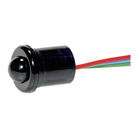
The SensePoint must be fitted into a suitably approved Exe
or Exd junction box fitted with a suitably approved cable
gland. This should be correctly installed before use. Cabling
should be multicore, three wire minimum, of conductor size
2.5 mm2 max.
The sensor should be fitted into a threaded hole within the
junction box and locked in place with a lock nut. Ensure that
junction box thread is compatible with sensor thread.
The sensor should be installed in a location free from direct
heat sources. It should be fitted such that it either points
downwards or horizontally. It is not recommended that the
sensor points upwards. See the technical handbook for
installation in forced air conditions.
Wiring connections are:-
4. OPERATIONS 4. OPERATIONS
3.1 WARNINGS
This apparatus is not suitable for use in
oxygen enriched atmospheres (>21%V/V).
Oxygen deficient atmospheres (<10%V/V)
may suppress sensor output.
Refer to local or national regulations
relative to installation at the site.
Operator should be fully aware of the action
to be taken if the gas concentration exceeds
an alarm level.
SensePoint should be protected from
mechanical impact. Installation should
consider not only the best placing for gas
leakage related to potential leak points,
gas characteristics and ventilation, but also
where the potential of mechanical damage
is minimized or avoided.
3.2 CAUTIONS
Atmospheres above 100% LEL may
suppress the sensor reading.
Do not modify or alter the sensor
construction as essential safety
requirements may be invalidated.
Install using certified Exe or Exd junction
box, connectors and glanding.
Dispose of in accordance with local disposal
regulations. Materials used -Fortron®
(PPS- Polyphenylene Sulphide).
3. SAFETY
4.2 CALIBRATION
Prior to calibration, allow the sensor to warm up for
approximately 10 minutes. Re-calibration should only be
attempted by qualified service personnel.
First zero the control system with no gas present on the
sensor. If combustible gas is suspected to be in the vicinity of
SensePoint, flow clean air over the sensor using a flow housing
(see below).
Fit a flow housing and connect a cylinder of either air, for a
zero, or a known concentration of gas in air, at approximately
the alarm point (e.g. 50% LEL), to the flow housing. Pass the
gas through the flow housing at a flow rate of approximately
1 l to 1.5 l per minute. Allow the sensor to stabilise. When
gassing with air, adjust the control card to indicate zero. For
span, the control card should be adjusted to indicate the
concentration of the target gas being applied. Remove the
flow housing and the gas supply.
Sensors should be calibrated at concentrations representative
of those to be measured. It is always recommended that
SensePoint is calibrated with the target gas it is to detect. If
this is not possible, then cross calibration can be used.
For calibration in fast flow conditions see the technical
handbook.
4.3 CROSS CALIBRATION PROCEDURE
When the SensePoint sensor is to be calibrated with a gas
which is different to the gas/vapour to be detected, the
following cross calibration procedure should be followed.
Table 1 lists gases according to the reaction they produce at
the detector. An eight star (8*) gas produces the highest
output while a one star (1*) gas produces the lowest output.
(These are not applicable at ppm levels.)
4. OPERATIONS
To calibrate the SensePoint sensor, obtain the star rating for
both the test gas and the gas to be detected from table 1.
These values may then be used in table 2 to obtain the
required meter setting when a 50% LEL test gas is applied to
the detector.
If a sensor is to be used to detect a gas other than that for
which it was calibrated, the required correction factor may be
obtained from table 3. The meter reading should be multiplied
by this number in order to obtain the true gas concentration.
IMPORTANT
Since combustible sensors require oxygen for correct
operation, a mixture of gas in air should be used for
calibration purposes.
Assuming an average sensor performance, the sensitivity
information in tables 1 to 3 is normally accurate to ± 20%.
Table 1: Star Rating of Gasses
7 8 9 10
6
Gas Star Rating
Acetone 4*
Ammonia 7*
Benzene 3*
Butane 4*
Diethyl ether 4*
Ethane 6*
Ethanol 5*
Ethyl acetate 3*
Ethylene 5*
Gas Star Rating
Hexane 3*
Hydrogen 6*
Methane 6*
Octane 3*
Propan-2-ol 4*
Propane 5*
Styrene 2*
Tetra hydrafuran 4*
Xylene 2*
The unit requires 200mA current with a nominal 3V supply.
Installation and service are to be performed by a qualified
installation engineer with the power to the sensor
disconnected.
SENSITIVE
(S)
NON
SENSITIVE
(NS) COMMON
(01)
SPARE
BROWN BLUE WHITE
SENSOR
