5062-26-NCL-EN 41
GasAlertMax XT II (continued)
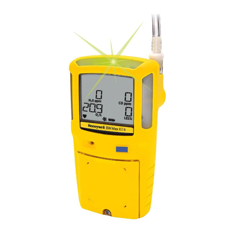
Note: Please refer to the instrument’s documentation (shipped with the product or available at www.gasmonitors.com) for complete instructions on common service
procedures. Improper servicing or maintenance may affect warranty eligibility. Honeywell assumes no liability for damages resulting from improper servicing or maintenance.
Legend Service Parts Order Number
BReplacement front enclosure (yellow) for GasAlertMax XT II XT-FC1-1
Replacement front enclosure (black) for GasAlertMax XT II XT-FC1B-1
GReplacement back enclosure (yellow) with screws for GasAlertMax XT II XT-BC1
Replacement back enclosure (black) with screws for GasAlertMax XT II XT-BC1B
OReplacement sensor enclosure with screw (yellow) with screw for GasAlertMax XT II XT-SC1
Replacement sensor enclosure with screw (black) with screw for GasAlertMax XT II XT-SC1B
HReplacement pump enclosure (yellow) with screw for GasAlertMax XT II XT-PC1
Replacement pump enclosure (black) with screw for GasAlertMax XT II XT-PC1B
DReplacement main PCB with screws for GasAlertMax XT II XT-MPCB2
EReplacement battery kit for GasAlertMax XT II XT-BAT-K1
FReplacement pump kit for GasAlertMax XT II XT-RPUMP-K1
Replacement alligator clip with screw for GasAlertMax XT II XT-AG-1
AReplacement LCD kit for GasAlertMax XT II XT-LCD-K1
Replacement screw kit for GasAlertMax XT II XT-SCREW-K1
How to Replace a Sensor
1. With detector OFF, use No. 1 Phillips screwdriver to loosen
retaining screw on pump enclosure (H)
2. Lift pump enclosure (H) so it unhooks from back enclosure (G)
3. Use No. 1 Phillips screwdriver to remove 6 screws from back
enclosure (G)
4. Lift back enclosure (G) straight up
5. Use No. 1 Phillips screwdriver to remove 2 screws from back
of PCB (D)
6. Lift PCB (D) together with battery and sensors straight up
7. Remove sensor (C, K, L) by sliding out or sensor (M) by pulling
straight up from PCB (D)
8. Insert new sensor (C, K, L, M) into PCB (D)
9. Replace PCB (D) and 2 screws and hand-tighten until firm
10. Replace back enclosure (G)
11. Replace 6 screws in the back enclosure (G) and
hand-tighten until firm
12. Replace pump enclosure (H) and hand-tighten retaining screw
until firm
How to Replace the Sensor Screen
1. With detector OFF, use No. 1 Phillips screwdriver to loosen
retaining screw on pump enclosure (H)
2. Lift pump enclosure (H) so it unhooks from back enclosure (G)
3. Use No. 1 Phillips screwdriver to remove 6 screws from back
enclosure (G)
4. Lift back enclosure (G) straight up
5. Use No. 1 Phillips screwdriver to remove 2 screws from back
of PCB (D)
6. Lift PCB (D) together with battery and sensors straight up
7. Remove sensor screen (N) from front enclosure (B) by pulling
straight up
8. Insert new sensor screen (N) into front enclosure (B)
9. Replace PCB (D) and 2 screws and hand-tighten until firm
10. Replace back enclosure (G)
11. Replace 6 screws in the back enclosure (G) and
hand-tighten until firm
12. Replace pump enclosure (H) and hand-tighten retaining screw
until firm

