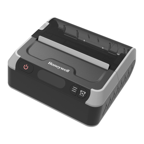
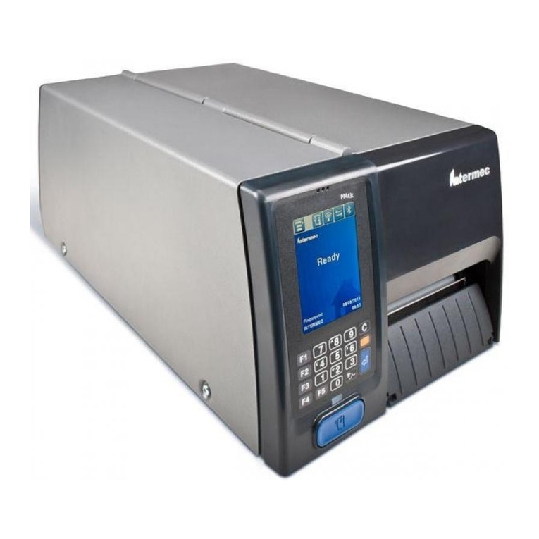
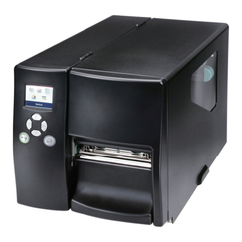
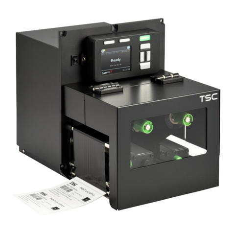
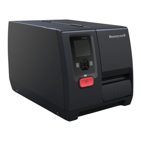
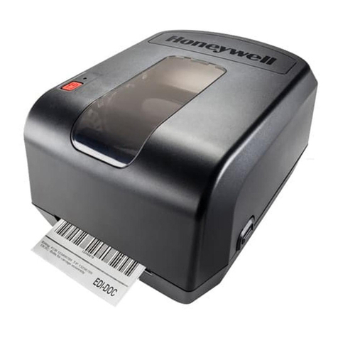
Honeywell PM42 Operating instructions

TITLE
Model
DOCUMENT NO.
PAGE
PM42 Service Repair Manual PM42 L3-GLBL-RPR-3872
(Rev A)
Page 1of 48
L3-GLBL-RPR-3872 (Rev A)
Revision History
Rev
ECN Number
Description
Updated Pages
Change Type
Released by
A
336577
First release
Te Chhang

TITLE
Model
DOCUMENT NO.
PAGE
PM42 Service Repair Manual PM42 L3-GLBL-RPR-3872
(Rev A)
Page 2of 48
L3-GLBL-RPR-3872 (Rev A)
Disclaimer
Honeywell International Inc. (“HII”) reserves the right to make changes in specifications and other information
contained in this document without prior notice, and the reader should in all cases consult HII to determine whether
any such changes have been made. The information in this publication does not represent a commitment on the part
of HII.
HII shall not be liable for technical or editorial errors or omissions contained herein: nor for incidental or
consequential damages resulting from the furnishing, performance, or use of this manual.
This document contains propriety information that is protected by copyright. All rights reserved. No part of this
document may be photocopied, reproduced, or translated into another language without the prior written consent of
HII.
© 2008 – 2011 Honeywell International Inc. All rights reserved.
Web Address: www.honeywellaidc.com
Trademarks
Metrologic, MetroSelect, MetroSet2, Master Diagnostics and TotalFreedom are trademarks or registered trademarks
of Metrologic Instruments, Inc. or Honeywell International Inc.
Microsoft, Windows, and Windows 95 are trademarks or registered trademarks of Microsoft Corporation.
Other product names mentioned in this manual may be trademarks or registered trademarks of their respective
companies and are the property of their respective owners.

TITLE
Model
DOCUMENT NO.
PAGE
PM42 Service Repair Manual PM42 L3-GLBL-RPR-3872
(Rev A)
Page 3of 48
L3-GLBL-RPR-3872 (Rev A)
Table of Contents
Disclaimer.....................................................................................................................................................................................2
Trademarks ...................................................................................................................................................................................2
Compliance and Safety....................................................................................................................................................5
General Precautions.....................................................................................................................................................................6
Safety Training..........................................................................................................................................................................6
Quality Training........................................................................................................................................................................6
Product ESD Information .........................................................................................................................................................6
High Level Recommended Repair Process ......................................................................................................................7
Cautions & Notes.............................................................................................................................................................8
Cover - Media Door Assembly.........................................................................................................................................9
Cover - Electronic Cover ................................................................................................................................................10
Front Panel Assembly....................................................................................................................................................11
Platen Roller ..................................................................................................................................................................13
Printhead .......................................................................................................................................................................14
Print Unit Components..................................................................................................................................................15
Printhead Lift Handle and Pressure Adjust Mechanism................................................................................................18
Printhead Lift Sensor Assembly.....................................................................................................................................20
Printhead Lift Assembly.................................................................................................................................................21
Media Guide Top Dancer Assembly ..............................................................................................................................22
Media Sensor Bottom Assembly ...................................................................................................................................24
Front Media Access Door ..............................................................................................................................................26
Ribbon Adjust Sub Assembly .........................................................................................................................................27
Ribbon Wrinkle Adjustment ..........................................................................................................................................28
Tear Bar .........................................................................................................................................................................29
Media Hanger and Edge Guides ....................................................................................................................................30
Ribbon Supply Assembly ...............................................................................................................................................31
Media Hanger and Edge Guides ....................................................................................................................................33
Base Assembly...............................................................................................................................................................34
Spine ..............................................................................................................................................................................35
Back Plate ......................................................................................................................................................................36
LCD Touch Panel and Display Assembly ........................................................................................................................37
Main Logic Board Assembly...........................................................................................................................................38
TITLE
Model
DOCUMENT NO.
PAGE
PM42 Service Repair Manual PM42 L3-GLBL-RPR-3872
(Rev A)
Page 4of 48
L3-GLBL-RPR-3872 (Rev A)
Power Supply Assembly ................................................................................................................................................39
Stepper Motor and Gear Drive Assembly .....................................................................................................................41
Example Screws & Torque Settings...............................................................................................................................47

TITLE
Model
DOCUMENT NO.
PAGE
PM42 Service Repair Manual PM42 L3-GLBL-RPR-3872
(Rev A)
Page 5of 48
L3-GLBL-RPR-3872 (Rev A)
Compliance and Safety
Compliance
This equipment has been tested and found to comply with limits for a Class A digital device, pursuant to Part 15 of
the FCC Rules. These limits are designed to provide reasonable protection against harmful interference when the
equipment is operated in a commercial environment. This equipment generates, uses and can radiate radio frequency
energy and, if not installed and used in accordance with the instruction manual, may cause harmful interference to
radio communications. Operation of this equipment in a residential area is likely to cause harmful interference, in
which case the user will be required to correct the interference at his own expense. Any unauthorized changes or
modifications to this equipment could void the users authority to operate this device. This device complies with Part
15 of the FCC Rules. Operation is subject to the following two conditions:
1. This device may not cause harmful interference.
2. This device must accept any interference received, including interference that may cause undesired
operation.
Notice
This Class A digital apparatus complies with Canadian ICES-003.
Remarque
Cet appareil numérique de la classe A est conforme à la norme NMB-003 du Canada.
Caution
Only trained personal should open and service the scanner as use of controls or adjustments or performance of
procedures other than those specified herein may result in dangerous laser light exposure. Never attempt to look at
the laser beam, even if the scanner appears to be nonfunctional. Doing so could result in hazardous laser light
exposure. The use of optical instruments with the laser equipment will increase eye hazard.
Standard Europeo
Warning
This is a class A product. In a domestic environment this product may cause radio interference in which case the
user may be required to take adequate measures.
Funkstöreigenschaften nach EN55022:1998
Warnung!
Dies ist eine Einrichtung der Klasse A. Diese Einrichtung kann im Wohnbereich Funkstörungen verursachen. In
diesem Fall kann vom Betreiber verlangt werden, angemessene Massnahmen durchzuführen.
Attenzione
Questo e’ un prodotto di classe A. Se usato in vicinanza di residenze private potrebbe causare interferenze radio che
potrebbero richiedere all’utilizzatore opportune misure.
Attention
Ce produit est de classe “A”. Dans un environnement domestique, ce produit peut être la cause
d’interférences radio. Dans ce cas l’utiliseteur peut être amené à predre les mesures adéquates.

TITLE
Model
DOCUMENT NO.
PAGE
PM42 Service Repair Manual PM42 L3-GLBL-RPR-3872
(Rev A)
Page 6of 48
L3-GLBL-RPR-3872 (Rev A)
General Precautions
This symbol within the document represents an important HSE Safety requirement/alert.
This symbol within the document represents an important quality step.
Safety Training
Consult the local HSE Cell Risk assessment to become familiar with any potential hazards while working with the
PM42 printer.
HSE training for this Scanner should include;
•Hand and Portable Tools
•Hazardous Chemical Management
•Laser Safety
•Lead Safety
•PPE
•Safety Awareness
Safety glasses must be worn.
Quality Training
Training per the local Honeywell site for Technicians/Repair personal should include;
•Soldering Verification
Product ESD Information
This product contains ESD sensitive components or ElectroStatic Discharge sensitive electronic parts. The
Electrostatic discharge is defined as the transfer of charge between bodies at different electrical potentials. An ESD
event has the ability to modify the electrical characteristics of a semiconductor device, possibly degrading or even
destroying it. ESD also may upset the normal operation of an electronic system, causing equipment malfunction or
failure.
ESD PREVENTION STEPS MUST BE USED DURING ANY REPAIRS OR MODIFICATIONS TO THIS
UNIT. PERFORM ALL WORK AT A CERITFIED ESD WORK STATION.

TITLE
Model
DOCUMENT NO.
PAGE
PM42 Service Repair Manual PM42 L3-GLBL-RPR-3872
(Rev A)
Page 7of 48
L3-GLBL-RPR-3872 (Rev A)
OPERATION:
High Level Recommended Repair Process
Step
Process
Reference Document
Location
Comments
1 Repair Unit SRD, SSP and STS Service Eng
Team Room
High level repair information is
referenece in the Service
Engineering Team Room and
Service Portal page (CSSP).
2 Check for hardware /
software updates
Service Procedures /
Technical Bulletins SAP
Applicable Service Procedures /
Technical Bulletins are listed on
Service Engineering team site
and the Service Portal page
(CSSP).
3 Functional Test SPP Test Eng Team
Room
SPP’s are listed on Test
Engineering team site and the
Service Portal page (CSSP).

TITLE
Model
DOCUMENT NO.
PAGE
PM42 Service Repair Manual PM42 L3-GLBL-RPR-3872
(Rev A)
Page 8of 48
L3-GLBL-RPR-3872 (Rev A)
OPERATION:
Cautions & Notes
•PM42 supports USB, serial, parallel, and Ethernet only.
•The functionalilty of the PM42 printers will be backward compatible with PM43 printers except the
following:
PM43 PM42 Backward compatibility
Touch panel Support Not support no
LCD 3.5(QVGA 320 x 240 pixels) 2.36 (480 (RGB) x 234) no
Print Mech Cast metal Print mech Sheet metal Print mech no
UI button 19(Number, F1~F5, …) 8 (Menu/Home, Enter/OK) no
BT, WiFi, RFID,
Touchless, RTC,
Speaker
Support Not support no

TITLE
Model
DOCUMENT NO.
PAGE
PM42 Service Repair Manual PM42 L3-GLBL-RPR-3872
(Rev A)
Page 9of 48
L3-GLBL-RPR-3872 (Rev A)
OPERATION:
Cover - Media Door Assembly
The media door assembly come as a complete assembly including the clear plastic window and 4 torx screws. The
clear plastic window is also available as a spare part.
Tools Required
Description
Torx Driver T20
Parts Required
Item
Part Number
Description
Qty
1
50124891-001FRE
FRE, ASSY, MEDIA DOOR, PM42 (include 4 – 50125239-001)
1
2
50125239-001FRE
FRE, SCREW MRT M4X8, Ф7, 100-Pack (16±0.8kgf/cm)
4
3
50124875-001FRE
FRE, Window, Media Door, PM42
1
Media Door Assembly Replacement
1. Lift the media door cover and remove the Torx screws securing the media door assembly.
Media Door Assembly T20 Torx Screw Media Window
1
2
3

TITLE
Model
DOCUMENT NO.
PAGE
PM42 Service Repair Manual PM42 L3-GLBL-RPR-3872
(Rev A)
Page 10 of 48
L3-GLBL-RPR-3872 (Rev A)
OPERATION:
Cover - Electronic Cover
Tools Required
Description
Torx Driver T20
Parts Required
Item
Part Number
Description
Qty
1
50124890-001FRE
FRE, Cover, EE, PM42
1
2
814-055-008FRE
Screw MRT M4X8 Black, 100-Pack (6±0.3kgf/cm)
4
Electronic Cover Replacement
1. Remove the torx screws (2 on media side and 2 on electronic side) that secure the electronic cover.
2. Lift the electronic cover up and away from the printer spine (main deck).
Electronic Cover Torx Screw
1
2
1
2

TITLE
Model
DOCUMENT NO.
PAGE
PM42 Service Repair Manual PM42 L3-GLBL-RPR-3872
(Rev A)
Page 11 of 48
L3-GLBL-RPR-3872 (Rev A)
OPERATION:
Front Panel Assembly
The front panel assembly is available as a complete assembly and individual replacement assemblies.
Tools Required
Description
Torx Driver T10
Torx Driver T20
Parts Required
Item
Part Number
Description
Qty
1
51024892-001FRE
FRE, Assy, Front Panel, w/o PCBA, PM42
1
2
50124882-001FRE
FRE, BUTTON FEED
1
3
50124625-032FRE
FRE, PCBA, UI Feed Button, PM42
1
4
50125473-001FRE
FRE, KEYPAD MEMBRANE
1
5
TBA
FRE, LABEL, EMBOSSED OVERLAY, PM42
1
6
50125130-001FRE
FRE, LCD, TFT, 2.36 INCH,480(RGB)*234
1
7
50124880-001FRE
FRE, LCD Window, PM42
1
8
50124625-002FRE
FRE, PCB S/A, PM42 – LCD
1
Front Panel Assembly Part Replacement
1. Remove the media cover door assembly and electronic cover assembly.
2. Remove the torx screws securing the front panel assembly from the electronic side and the torx screw next to
the meda access door.
3. Disconnect the ground (GND) wire and the interface cable from the main logic board (MLB).
4. Release the two locking taps on the front panel assembly and pull the front panel assembly away from the spine
(main deck).

TITLE
Model
DOCUMENT NO.
PAGE
PM42 Service Repair Manual PM42 L3-GLBL-RPR-3872
(Rev A)
Page 12 of 48
L3-GLBL-RPR-3872 (Rev A)
1
2
3
4
5
6
7

TITLE
Model
DOCUMENT NO.
PAGE
PM42 Service Repair Manual PM42 L3-GLBL-RPR-3872
(Rev A)
Page 13 of 48
L3-GLBL-RPR-3872 (Rev A)
OPERATION:
Platen Roller
Tools Required
Description
Torx T20
Parts Required
Item
Part Number
Description
Qty
1
50124891-001FRE
FRE, ASSY, MEDIA DOOR, PM42
1
Platen Roller Assembly Replacement
1. Raise or open the Printhead
2. Rotate the platen roller latch clockwise to detach the platen roller assembly from the printer and pull the platen
roller away from the printer.
3. Insert the replacement platen roller into the printer and secure it by turning the latch counterclockwise.
Platen Roller Assembly
Cleaning Platen Rollers
Recommended that the installed platen rollers be cleaned. To clean the platen roller, the following are needed:
• Silicone cleaning fluid
• Lint-free cleaning cloth
• Thermal printhead cleaning swab, wipe, or pen
1

TITLE
Model
DOCUMENT NO.
PAGE
PM42 Service Repair Manual PM42 L3-GLBL-RPR-3872
(Rev A)
Page 14 of 48
L3-GLBL-RPR-3872 (Rev A)
OPERATION:
Printhead
The handstrap is attached to the bottom housing. It can be removed and installed without opening the unit.
Tools Required
Description
Isopropyl alcohol solution
Parts Required
Item
Part Number
Description
Qty
1
50126706-001FRE
FRE, ASSY, PRINTHEAD, 203DPI, PM42
1
2
50126707-001FRE
FRE, ASSY, PRINTHEAD, 300DPI, PM42
1
3
50126708-001FRE
FRE, ASSY, PRINTHEAD, 406DPI, PM42
1
Printhead Assembly Replacement
1. Turn the printhead lift lever counterclockwise to raise the printhead
2. Detach the magnetic pressure arm from the printhead bracket and disconnect the two cables from the printhead
as you remove it from the printer.
3. Connect the two printhead cables to the new printhead
4. As you insert the new printhead bracket into the printer, make sure the metal arms on the printhead go around
the magnetic pressure arm. Attach the magnetic pressure arm to the printhead.
Thermal Printhead
Cleaning Printhead
Recommended that the installed printhead be cleaned. To clean the printhead, the following are needed:
• Silicone cleaning fluid
• Lint-free cleaning cloth
• Thermal printhead cleaning swab, wipe, or pen
1
Printhead Cables
Magnetic Pressure Arm

TITLE
Model
DOCUMENT NO.
PAGE
PM42 Service Repair Manual PM42 L3-GLBL-RPR-3872
(Rev A)
Page 15 of 48
L3-GLBL-RPR-3872 (Rev A)
OPERATION:
Print Unit Components
This section covers the replacement and installation of the print unit assembly that has several components. This
section addresses the bottom base print mechanism and the printhead adjustment assembly. The spare bottom
base print mechanism does not include the media guide assembly and sensor.
Tools Required
Description
Torx Driver T20
Parts Required
Item
Part Number
Description
Qty
1
644-052-001FRE
FRE, Bar Connecting
1
2
50126032-001FRE
FRE, Bottom Assembly
1
3
50125236-001FRE
FRE, SCREW MRT M4X12 Ф12, 50-Pack (16±0.8kgf/cm)
1
4
1-994059-012
FRE, SCREW MRT M4X12 ZP (16±0.8kgf/cm)
1
Bottom Base Print Mechanism Replacement
1. Turn the printhead lift lever counterclockwise to raise the printhead.
2. Remove the platen roller assembly.
3. Remove the drive pulley to access the torx screw underneat.
4. Remove the 4 torx screws securing the bottom base print mechanism assembly
IMPORTANT!!: Make note of the guide posts and position of media guide assembly adjustment lever as you pull
the print mechanism away from the spine (main deck). See Figure 2.
5. Remove the tear bar and reverse the procedure for installation of new print mechanism assembly
Location of torx securing the print mechanism assembly
3

TITLE
Model
DOCUMENT NO.
PAGE
PM42 Service Repair Manual PM42 L3-GLBL-RPR-3872
(Rev A)
Page 16 of 48
L3-GLBL-RPR-3872 (Rev A)
Printhead Pressure Adjust Assembly Replacement
1. Turn the printhead lift lever counterclockwise to raise the printhead.
2. Remove the 5 torx screws securing the printhead pressure adjust assembly.
3. Prior to removing the printhead pressure adjust assembly, it is IMPORTANT to note the position of the crank
lever and guide posts.
4. Reverse the procedure for installing the replacement printhead pressure adjust assembly.
Printhead Pressure Adjust Assembly include torque pattern
Media Gap Guide
Adjustment lever
2
3
4
1
4
x5
Crank Lever
Position

TITLE
Model
DOCUMENT NO.
PAGE
PM42 Service Repair Manual PM42 L3-GLBL-RPR-3872
(Rev A)
Page 17 of 48
L3-GLBL-RPR-3872 (Rev A)
1
2

TITLE
Model
DOCUMENT NO.
PAGE
PM42 Service Repair Manual PM42 L3-GLBL-RPR-3872
(Rev A)
Page 18 of 48
L3-GLBL-RPR-3872 (Rev A)
OPERATION:
Printhead Lift Handle and Pressure Adjust Mechanism
This section cover the replacement of printhead lift handle and pressure adjust assembly. The printhead lift handle
is used to release the media (label) and ribbon for replacement. The pressure adjust assembly is part of the
printhead adjust assembly to adjust the printhead pressure against the platen roller for different media thickness.
The printhead pressure adjust assembly has to be removed first prior to removing the printhead lift handle and
pressure adjust assembly.
Tools Required
Description
Torx Driver T10
Torx Driver T20
Parts Required
Item
Part Number
Description
Qty
1
50125896-001FRE
FRE, Assy, Pressure Adjust Sub, PM42
1
2
50125631-001FRE
FRE, Pressure Adjust
1
3
50125623-001FRE
FRE, Head Lift Lever, PM42 (include 800-619-008)
1
4
1-994059-012
FRE, SCREW MRT M4X12 ZP, T20 (16±0.8kgf/cm)
2
5
800-619-008
SCREW MRT 3X8 FBZ NYLON PATCH, T10 (6±0.3 kgf.cm)
1
Printhead Lift Handle
1. Remove the printhead pressure assembly.
2. Remove the torx securing the printhead lift handle with a Torx driver T10 as shown on Figure 1 and remove the
printhead Lift handle away from the printhead pressure adjust assembly. It is important to make note on how
the printhead lift handle is attached to the pressure adjust assembly.
Pressure Adjust Assembly Replacement
1. Remove the printhead pressure assembly
2. Remove the 2 torx screws securing the pressure adjust holder against pressure adjust assembly and lift
the pressure adjust holder away to remove the pressure adjust assembly for replacement. It is important to
note the fittings.
3. Reverse the procedure for installing replacement of pressure adjust assembly.
5

TITLE
Model
DOCUMENT NO.
PAGE
PM42 Service Repair Manual PM42 L3-GLBL-RPR-3872
(Rev A)
Page 19 of 48
L3-GLBL-RPR-3872 (Rev A)
Pressure Adjust
Holder
1
4
2
3
X2

TITLE
Model
DOCUMENT NO.
PAGE
PM42 Service Repair Manual PM42 L3-GLBL-RPR-3872
(Rev A)
Page 20 of 48
L3-GLBL-RPR-3872 (Rev A)
OPERATION:
Printhead Lift Sensor Assembly
Printhead lift sensor senses when the printhead lifted.
Tools Required
Description
Torx Driver T10
Torx Driver T20
Parts Required
Item
Part Number
Description
Qty
1
236-261-001FRE
FRE, Printhead Lift Sensor Assembly, PM42
1
Printhead Lift Sensor Assembly Replacement
1. Remove the 2 torx screws securing the headlift sensor assembly.
2. Unplug the sensor cable assembly from the MLB and lift the headlift sensor away
3. Reverse the procedure to install replacement headlift sensor assembly
Headlift Sensor Assembly
2
1
Other manuals for PM42
2
Table of contents
Other Honeywell Label Maker manuals

Honeywell
Honeywell PC42T User manual

Honeywell
Honeywell PC42T User manual

Honeywell
Honeywell MPD31D User manual

Honeywell
Honeywell MPD31D User manual

Honeywell
Honeywell PM23c User manual

Honeywell
Honeywell PC42d Operating instructions

Honeywell
Honeywell PX940 User manual

Honeywell
Honeywell PM42 User manual