Honeywell VT8800 User manual

INSTALLATION INSTRUCTIONS
69-1731
VT8800/WT8800
Water Heater Controls
APPLICATION
The VT8800/WT8800 Water Heater Control System is a
modular control package which combines standing pilot,
gas flow control, temperature sensing and setpoint
adjustment features. These controls were designed
specifically for gas-fired atmospheric hot water tank
heating applications. The ignition source is a standing
pilot lighting the main burner flame.
VT8800/WT8800 Controls provide high temperature
appliance shutdown and all gas ignition safety functions,
controlling gas flow, ignition source and water
temperature.
The control uses two temperature sensors and a special
control algorithm to operate the main valve, accordingly.
The specific application of the VT8800/WT8800 System
is the responsibility of the appliance manufacturer. This
specification refers to the valve (VT8800) and the control
(WT8800).
SPECIFICATIONS
IMPORTANT
VT8800/WT8800 Controls provide direct
replacement only.
Body Pattern: VT8800: 90 degrees with 1/2 in. inlet and
1/2 in. inverted flare outlet.
Mounting: Mounting in upright position only.
Control Input:
Voltage Minimum: 350 mV dc, open circuit.
Voltage Maximum: 850 mV dc, open circuit.
Capacity: See Table 1.
Conversion: Use conversion factors in Table 2 to
convert capacities for other gases.
Regulation Range:
VT8800 with 1/2 in. NPT inlet and 1/2 in. Inverted Flare
Outlet:
Natural Gas:
Minimum: 30,000 Btuh.
Maximum: 85,000 Btuh.
LP Gas:
Minimum: 40,000 Btuh.
Maximum: 85,000 Btuh.
Ambient Temperature Range:
32°F to 140°F (0°C to 60°C)
Approvals:
Canadian Standards Association (CSA): Number
158158-1482778.
Dimensions:
See Fig. 1.
PLANNING THE INSTALLATION
WARNING
Fire or Explosion Hazard.
Can cause severe injury, death or property
damage.
Follow these warnings exactly:
1. Plan the installation as outlined below
2. Plan for frequent maintenance as described in
the Maintenance section.
3. Review the following conditions that can apply
to your specific installation and take the
precautionary steps provided.
Frequent Cycling
This control is designed for use on appliances that
typically cycle three to five times a day. In year-round
applications with greater cycling rates of 10,000 cycles
annually, the control can wear out more quickly. Perform
a monthly checkout.
69-1731.fm Page 1 Monday, October 10, 2005 11:02 AM

VT8800/WT8800 WATER HEATER CONTROLS
69-1731 2
Fig. 1. VT8800/WT8800 dimensions in in. (mm).
Water or Steam Cleaning
If a control gets wet, replace it. If the appliance is likely to
be cleaned with water or steam, protect (cover) the
control and wiring from water or steam flow. Mount the
control high enough above the bottom of the cabinet so it
does not get wet during normal cleaning procedures.
High Humidity or Dripping Water
Dripping water can cause the control to fail. Never install
an appliance where water can drip on the control. In
addition, high ambient humidity can cause the control to
corrode and fail. If the appliance is in a humid
atmosphere, make sure air circulation around the control
is adequate to prevent condensation. Also, regularly
check out the system.
Corrosive Chemicals
Corrosive chemicals can attack the control, eventually
causing a failure. If chemicals are used for routine
cleaning, avoid contact with the control. Where chemicals
are suspended in air, as in some industrial or agricultural
applications, protect the control with a cover.
Dust or Grease Accumulation
Heavy accumulations of dust or grease can cause the
control to malfunction. Where dust or grease can be a
problem, provide covers for the control to limit
contamination.
1-1/2
(38)
4-3/4 (121)
4-11/16
(119)
1-15/32
(37)
4-29/32 (125)
3-1/4 (83)
1-1/32
(26)
13/16
(21)
1/16
(2)
M23034
OUT
69-1731.fm Page 2 Monday, October 10, 2005 11:02 AM

VT8800/WT8800 WATER HEATER CONTROLS
3 69-1731
Table 1. Capacity of VT8800
aCapacity based on 1000 Btu/feet3, 0.64 specific gravity natural gas at 1 in. wc pressure drop (37.3 MJ/meter3, 0.64
specific gravity natural gas at 0.25 kPa pressure drop).
bValves are guaranteed at 77 percent of the rating.
Fig. 2. Typical capacity curve for VT8800 Family Water Heater Control System.
Table 2. Gas Capacity Conversion Factor.
Heat
Excessively high temperature can damage the control.
Make sure the maximum ambient temperature at the
control does not exceed the rating of the control. If the
appliance operates at very high temperatures, use
insulation, shielding, and air circulation, as necessary, to
protect the control. Proper insulation or shielding should
be provided by the appliance manufacturer; verify proper
air circulation is maintained when the appliance is
installed.
INSTALLATION
When Installing This Product…
1. Read these instructions carefully. Failure to follow
them could damage the product or cause a
hazardous condition.
2. Check the ratings given in the instructions and on
the product to make sure the product is suitable for
your application.
3. Installer must be a trained, experienced service
technician.
4. After installation is complete, check out product
operation as provided in these instructions.
Model
Size (Inlet x Outlet),
in.
Capacity (at 1 in. wc
pressure dropa,b)
Minimum Regulated
Capacity
Maximum Regulated
Capacity
VT8800 1/2 NPT x 1/2 Inverted
Flare 50 ft3/hr (1.4 m3/hr) 30 ft3/hr (0.85 m3/hr) 85 ft3/hr (2.8 m3/hr)
Gas (Btu/ft3) Specific Gravity Multiply Listed Capacity By
Manufactured (500) 0.60 0.516
Mixed (800) 0.70 0.765
Propane (2500) 1.55 1.62
M23035
DIFFERENTIAL PRESSURE (IN. W.C.)
NATURAL GAS FLOW (KBTU/H)
60
70
50
40
30
20
0.90 0.95 1.00 1.05 1.10 1.15 1.20 1.25 1.30
100
90
80
1 IN. CAPACITY
69-1731.fm Page 3 Monday, October 10, 2005 11:02 AM

VT8800/WT8800 WATER HEATER CONTROLS
69-1731 4
WARNING
Fire or Explosion Hazard.
Can cause severe injury, death or property
damage.
Follow these warnings exactly:
1. To avoid dangerous accumulation of fuel gas,
turn off gas supply at the appliance service
valve before starting installation, and perform
Gas Leak Test after completion of installation.
2. Always install a sediment trap in gas supply line
to prevent contamination of ignition system
control.
3. Follow the appliance manufacturer instructions
if available; otherwise, use these instructions as
a guide.
WARNING
Scalding Hazard.
Can cause burns, severe injury or death.
Always use a direct replacement sensor assembly
when replacing upper or lower temperature
sensor.
Location
The VT8800/WT8800 are mounted on the outside of the
water heater tank. See Fig. 2.
Install Control to Water Tank
1. To install the water heater control, screw the plate
bracket into the spud until the bracket is square.
Use a maximum torque of 50 ft. lb (two-piece
design only).
2. To install one-piece bracket design, screw bracket
into the spud until the bracket is square.
3. Position the valve bracket tab over the plate bracket
slot and slide down (two piece design).
4. Snap the valve into tabs of the valve bracket
assembly with the inverted flare outlet facing down.
Secure valve using one screw (two piece design).
5. Install WT8800 control electronics on the three pins
of the gas valve and snap into place. Secure with
one screw.
6. Be certain to mount the VT8800/WT8800 so that
the gas flow is in the direction of the arrow on the
inlet side of the control.
7. Follow steps in Connect Gas Supply section, which
follows.
IMPORTANT
These water heater system controls are shipped
with protective seals over the inlet and outlet tap-
pings. Do not remove the seals until ready to
connect the piping.
Fig. 3. Mounting the VT8800 on the water heater tank.
Connect Gas Supply
All piping must comply with local codes and ordinances or
with the National Fuel Gas Code (ANSI Z223.1 NFPA No.
54), whichever applies. Tubing installation must comply
with approved standards and practices.
1. Use new, properly reamed pipe free from chips. If
tubing is used, make sure the ends are square,
deburred and clean. All tubing bends must be
smooth and without deformation.
2. Run pipe or tubing to the water heater control. If
tubing is used, obtain a tube-to-pipe coupling to
connect the tubing to the control.
3. Install a sediment trap in the supply line to the water
heater control. See Fig. 3.
Table 3. NPT Pipe Thread Length (in.).
Pipe
Size
Thread Pipe
This Amount
Maximum Depth Pipe can be
inserted into Control
1/2 3/4 1/2
M23036
GAS LINES
CONNECTED
MOUNTING
DRY SPUD
WELDED
TO TANK
VT8800/
WT8800
69-1731.fm Page 4 Monday, October 10, 2005 11:02 AM

VT8800/WT8800 WATER HEATER CONTROLS
5 69-1731
Fig. 4. Install a sediment trap in the supply line.
WARNING
Explosion Hazard.
Can cause severe injury, death or property
damage.
Check for gas leaks with soap and water solution
any time work is done on a gas system.
4. Apply a moderate amount of good quality pipe com-
pound, leave two end threads bare. On LP installa-
tions, use a compound resistant to LP gas. Do not
use pipe dope on the outlet. See Fig. 4.
Fig. 5. Use a moderate amount of pipe compound.
5. Remove the seals over the water heater control
inlet and outlet, if necessary.
6. Connect the pipe to the water heater control inlet
and outlet. Use a wrench on the square end of the
water heater control. Maximum torque on the inlet is
40 ft. lb.; maximum torque on the outlet is 25 ft.lb.
7. Position compression fitting in pilot outlet and
engage threads. See Fig. 5 for controls and
connections. Turn until finger tight, then tighten one
more turn with wrench. Do not overtighten.
Fig. 6. Water heater controls and connections.
CAUTION
Contamination Hazard.
Can cause equipment malfunction.
Do not use thread tape sealants to seal the gas
supply to the control.
a. Use a pipe dope compound to seal the
connection.
b. Use only ANSI-approved compounds.
Wiring
Follow the wiring instructions furnished by the appliance
manufacturer, if available, or use the general instructions
provided below. When these instructions differ from the
appliance manufacturer, follow the appliance
manufacturer instructions. Make sure wiring insulation
does not get cut by sharp edges.
NOTE: All wiring must comply with applicable electrical
codes and ordinances.
Connect control circuit to the water heater control using
the wiring diagram in Fig. 7.
HORIZONTAL
DROP
PIPED
GAS
SUPPLY
3 IN.
(76 MM)
MINIMUM IGNITION
SYSTEM
CONTROL
TUBING
GAS
SUPPLY
HORIZONTAL
DROP
3 IN.
(76 MM)
MINIMUM
RISER
M23101
1
1
WARNING
EXPLOSION HAZARD.
FAILURE TO FOLLOW PRECAUTIONS CAN
RESULT IN A GAS-FILLED WORK AREA.
SHUT OFF THE MAIN GAS SUPPLY BEFORE REMOVING END CAP.
TEST FOR GAS LEAKAGE WHEN INSTALLATION IS COMPLETE.
ALL BENDS IN METALLIC TUBING SHOULD BE SMOOTH.
STATUS
IGNITION
SYSTEM
CONTROL
STATUS
TWO
IMPERFECT
THREADS
IGNITION
SYSTEM
CONTROL
THREAD PIPE THE AMOUNT
SHOWN IN TABLE 3 FOR INSERTION
INTO IGNITION SYSTEM CONTROL
APPLY A MODERATE AMOUNT OF
PIPE COMPOUND ONLY TO PIPE
(LEAVE TWO END THREADS BARE).
M16269
PIPE
M23037
STATUS
GAS LINE
CONNECTION
PIEZO IGNITOR
SWITCH
UPPER
SENSOR
FRONT VIEW
BOTTOM VIEW
PRESSURE
TAP
MAIN GAS
PILOT
GAS
LOWER
SENSOR
IGNITOR
LEAD
DEVICE
KNOB
STATUS
INDICATOR
THERMOPILE
69-1731.fm Page 5 Monday, October 10, 2005 11:02 AM

VT8800/WT8800 WATER HEATER CONTROLS
69-1731 6
Fig. 7. Simplified wiring diagram.
Assembly of Thermistors
1. The thermistor is captured in a plastic bracket.
2. The thermistor bead shall be held in contact with
the tank surface by pushing the plastic bracket on a
threaded stud (10-32 at least 3/8 in. long) that is
welded to the tank.
NOTE: The position of the studs need to be optimized
by application. A general guideline to start is
6 in. to 8 in. from the top for the top sensor and
6 in. to 8 in. from the bottom of the tank for the
bottom sensor.
Fill Tank
Refer to the appliance manufacturer instructions to fill the
tank with water.
Pilot Gas and Lighting Procedure
1. Start by turning the device knob to Pilot, push the
knob down, and hold in position. (The pilot valve
opens and allows gas to flow into the pilot burner.)
2. Depress the piezo igniter to light the pilot flame and
hold the knob in until the status indicator) starts to
blink (approximately 30 seconds).
NOTE: Status indicator should blink every three
seconds. If not, check the error code table 6.
3. Release the knob and turn to the desired
temperature setting. The burner will come on if
water temperature is significantly below the
temperature setpoint.
Turn on Main Burner
Follow the instructions provided by the manufacturer or
turn up the temperature at the setpoint knob.
WARNING
Scalding Hazard.
Can cause burns, severe injury or death.
Never move setpoint knob past the Hot setting
unless extremely hot water is desired. Always
check water temperature at the faucet and
readjust until comfortably warm to the touch.
Consider the ages and health of all who will come
in contact with heated water.
Perform Gas Leak Test
WARNING
Fire or Explosion Hazard.
Can cause severe injury, death or property
damage.
Check for gas leaks with soap and water solution
any time work is done on a gas system.
CAUTION
Water Damage Hazard.
Can damage electrical components in the
VT8800/WT8800.
Do not spray soap and water solution on the
VT8800/WT8800 housing. Do not use an
excessive amount of soap and water to perform
the gas leak test.
Gas Leak Test
1. Paint pipe connections upstream of the water
heater control with rich soap and water solution.
Bubbles indicate a gas leak.
2. If a leak is detected, tighten the pipe connection.
3. Stand clear of the burner while lighting to prevent
injury caused from hidden leaks that could cause
flashback in the appliance vestibule.
4. With the burner in operation, paint the pipe joints
(including adapters) and the control inlet and outlet
with rich soap and water solution.
5. If another leak is detected, tighten the adapter
screw, joints, and pipe connections.
6. Replace the part(s) if a leak cannot be stopped.
UPPER
SENSOR
M23038
THERMOPILE
LOWER
SENSOR
RED
WHITE
SPARK
ROD
69-1731.fm Page 6 Monday, October 10, 2005 11:02 AM

VT8800/WT8800 WATER HEATER CONTROLS
7 69-1731
Check and adjust Gas Input and Burner
Ignition
WARNING
Fire or Explosion Hazard.
Can cause severe injury, death or property
damage.
Follow these warnings exactly:
1. Do not exceed input rating stamped on
appliance nameplate or manufacturer
recommended burner orifice pressure for size
orifice(s) used. Make certain primary air supply
to burner is properly adjusted for complete
combustion. Follow instructions of appliance
manufacturer.
2. IF CHECKING GAS INPUT BY CLOCKING
GAS METER: Make certain there is no gas flow
through the meter other than to the appliance
being checked. Other appliances must remain
off with the pilots extinguished (or that
consumption must be deducted from the meter
reading). Convert flow rate to Btuh as
described in form number 70-2602, Gas
Controls Handbook, and compare to Btuh input
rating on appliance nameplate.
3. IF CHECKING GAS INPUT WITH
MANOMETER: Make sure the manual gas
shutoff switch is in the OFF position before
removing outlet pressure tap plug to connect
manometer (pressure gauge). Also, move the
manual gas shutoff switch to the OFF position
when removing the gauge and replacing the
plug. Also shut off gas supply before
disconnecting manometer and replacing plug.
Repeat Gas Leak Test at plug with main burner
operating.
1. Check the full rate manifold pressure listed on the
appliance nameplate. Water heater control full rate
outlet pressure should match this rating.
2. With burner operating, check the water heater
control flow rate using the meter clocking method or
check pressure using a manometer connected to
the outlet pressure tap on the water heater control.
See Fig. 5.
MAINTENANCE
WARNING
Fire or Explosion Hazard.
Can cause severe injury, death or property
damage.
Do not attempt to take the control apart or clean it.
Improper cleaning or reassembly can cause gas
leakage.
The maintenance program should include regular
checkout of the control as outlined in the Startup and
Checkout section, and the control system as described in
the appliance manufacturer literature.
Maintenance frequency must be determined individually
for each application. Some considerations are:
1. Cycling frequency. Appliances that may cycle
10,000 times annually should be checked monthly.
2. Intermittent use. Appliances that are used
seasonally should be checked before shutdown and
again before the next use.
3. Consequence of unexpected shutdown. Where the
cost of an unexpected shutdown would be high, the
system should be checked more often.
4. Dusty, wet or corrosive environment. Since these
environments can cause the control to deteriorate
more rapidly, the system should be checked more
often.
The system should be replaced if:
1. It does not perform properly on checkout or
troubleshooting.
2. The control is likely to have operated for more than
150,000 cycles.
3. The control is wet or looks as if it has been wet.
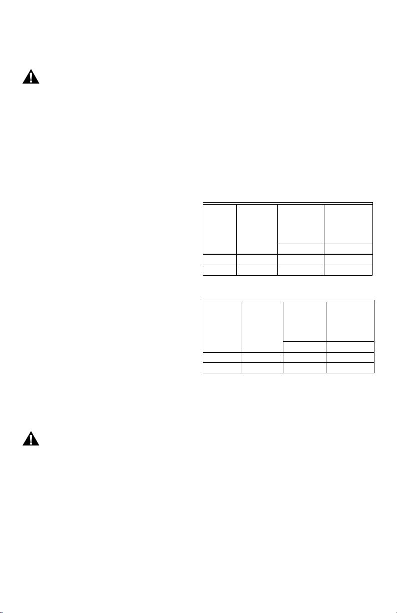
Table 4. Pressure Regulator Specification Pressures
(in. wc).
Table 5. Pressure Regulator Specification Pressures
(kPa).
TROUBLESHOOTING
Troubleshooting With Status Indicator
Assistance
1. Pilot burner must be lit. If not, push and hold Pilot
knob and light pilot with piezo. Error code will be
displayed when thermopile heats up. Error code
can be recognized by counting the number of
flashes of the status indicator after a three second
pause. One single flash indicates that the control is
in normal operation.
2. Observe status indicator on control; check and
repair the system as noted in Table 6. Flash codes
are displayed with a three-second delay between
cycles. Startup fault indicator will flash codes with
one-second delay followed by a six-second solid on
time and then a one-second delay. The
six-second solid on time indicates that the control is
not able to restart the system and will not allow gas
to the pilot unless knob is depressed and held in. A
continuous solid light indicates system shutdown
when knob is turned from a temperature setting to
OFF position. When the solid light is present, the
Type of
Gas
Nominal
Inlet
Pressure
Range
Factory Set
Nominal
Outlet
Pressure
Setting Range
Full Rate Full Rate
Natural 5.0 to 7.0 4.0 4.0 to 5.0
LP 12.0 to 14.0 10.0 9.0 to 11.0
Type of
Gas
Nominal
Inlet
Pressure
Range
Factory Set
Nominal
Outlet
Pressure Setting Range
Full Rate Full Rate
Natural 1.2 to 1.7 1.0 1.0 to 1.2
LP 2.9 to 3.9 2.5 2.2 to 3.0
69-1731.fm Page 7 Monday, October 10, 2005 11:02 AM

VT8800/WT8800 WATER HEATER CONTROLS
69-1731 8
pilot and main valve will not hold. When the status
indicator goes out, the user can restart the system.
(Approximate shutdown time is one minute.)
3. After status indicator analysis and appliance repair
is complete, turn device knob to OFF, wait until the
indicator goes out, then perform lighting procedure.
4. Status indicator light should be in normal mode (1
flash) and turning the device knob past the water
temperature in the tank should turn on the main
burner.
5. In the event of multiple failure codes, the next
failure code follows the previous failure code by
approximately three seconds with higher flash
count first.
Troubleshooting Without Status Indicator
Assistance
Follow diagram in Fig. 8.
aFlashes are approximately 1/10th second in duration with approximately three seconds between groups of flashes.
Table 6. Troubleshooting with Status Light Visual Indication.
Status Light Number of LED FlashesaIndicates Service Action
1 flash Normal operation Control is powered, pilot is lit.
2 flashes Low supply voltage from
thermopile, operate normally if
enough voltage is available.
Inspect thermopile connection to
valve, flame coverage on
thermopile, inspect orifice
assembly for dirt, check inlet
pressure, run open circuit
thermopile output test and change
thermopile if output is low.
3 flashes Sensor or Valve failure, Pilot On,
Main Valve Off.
Restart control. If main turns on
after restart, replace sensor. If main
does not turn on after restart,
replace valve.
4 flashes Valve overheat failure, Pilot Off/
Main Valve Off.
Replace Valve and Control.
5 flashes Lower sensor failure, Pilot
On/Main Valve off.
Verify sensor is connected to
control.
Verify sensor assembly is attached
to tank.
Run Sensor Calibration check.
Replace Sensor and Control.
6 flashes Upper sensor failure, Pilot On/
Main Valve Off.
Verify sensor is connected to
control.
Verify sensor assembly is attached
to tank.
Run Sensor Calibration check.
Replace Sensor and Control.
7 flashes Electronic Control Failure, Pilot
On or Off/Main Valve Off.
Replace Control.
8 Flashes Valve Failure, Pilot Off/Main
Valve Off.
Replace Valve and Control.
6-second long
flash, plus 4, 7,
or 8 flash
Pilot stays lit only when control
knob depressed in PILOT
position.
Follow flash code error service
action.
Continuous
solid light
System shutdown/safety
interlock
Wait until light goes out to restart
control.
69-1731.fm Page 8 Monday, October 10, 2005 11:02 AM

VT8800/WT8800 WATER HEATER CONTROLS
9 69-1731
Fig. 8. Troubleshooting Without Status Light.
Thermopile Output Check.
1. Turn device knob to OFF.
2. Disconnect thermopile leads.
3. Turn device knob to PILOT, hold down knob to light
pilot burner. Hold the knob down for five or more
minutes.
4. After five minutes, check thermopile output by
connecting the voltmeter to the positive red lead
and negative white leads.
5. Output should be at least 350 mV. (See Fig. 8.)
Connect the 3.6 ohm resistor between the two ther-
mopile leads, the voltage should be at or higher
than one half of the open circuit voltage.
6. The terminals prevent miswiring of positive (1/4 in.)
and negative (3/16 in.) leadwires.
7. Flame must envelop thermopile at Hot Junction
(3/8 in. below tip).
8. Keep heat away from cold junction (brass sleeve)
for maximum output.
Fig. 9. Thermopile output.
Sensor Calibration Check
1. Turn device knob to OFF.
2. Disconnect sensor leads (1 x 4 connector).
3. Use ohmmeter to check resistance on upper or
lower sensor (see wiring diagram).
4. Typical resistance values will be between 1700
ohms (160°F tank temperature) and 9300 ohms
(80°F tank temperature).
5. Replace sensor assembly if you measure open
circuit or the ohms reading is significantly out of
range.
INSTRUCTIONS TO THE
HOMEOWNER
WARNING
Fire or Explosion Hazard.
Can cause severe injury, death or property
damage.
1. IF YOU SMELL GAS:
• Turn off the gas supply at the appliance
service valve. On LP systems, turn off the
gas supply at the gas tank.
• Do not light any appliances in the house.
• Do not touch electrical switches or use the
phone. Leave the building and use a
neighbor’s phone to call your gas supplier.
• If you cannot reach your gas supplier, call
the fire department.
2. The water heater control must be replaced in
event of any physical damage, tampering, bent
terminals, missing or broken parts, stripped
threads or evidence of exposure to heat.
TURN DEVICE KNOB FROM OFF TO
PILOT, PRESS DOWN KNOB AND HOLD,
LIGHT PILOT BY DEPRESSING PIEZO
IGNITION BUTTON, PILOT SHOULD
LIGHT
CHECK:
• WIRING OF THERMOPILE LEADS
• FLAME COVERAGE OF THERMOPILE
• THERMOPILE OUTPUT IS TOO LOW-RUN
•THERMOPILE OUTPUT CHECK
STATUS LIGHT SHOULD FLASH AFTER
1 MINUTE, LED WILL FLASH NORMAL
SINGLE BLINK, RELEASE THE DEVICE
KNOB, PILOT SHOULD REMAIN LIT
TURN DEVICE KNOB TO DESIRED
TEMPERATURE SETTING, BURNER WILL
TURN ON ONLY IN ACTIVE CALL FOR
HEAT (WATER TEMPERATURE IS LESS
THAN TEMPERATURE SETTING MINUS
DIFFERENTIAL)
SYSTEM OK
CHECK:
• EXCESSIVE INLET PRESSURE
• TANK TEMPERATURE IS AT OR CLOSE
TO SET POINT.
• RUN SENSOR CALIBRATION CHECK
NO
NO
NO
YES
YES
YES
M22536C
TROUBLESHOOTING GUIDE WITHOUT STATUS LIGHT
CHECK:
• INLET PRESSURE
• MAKE SURE AIR IS BLED OUT OF SYSTEM
• PIEZO SPARKING TO THERMOPILE
• CLOGGED PILOT ORIFICE
• GAS LEAK IN PILOT TUBING CONNECTIONS
M22535B
TIME (MINUTES)
OUTPUT (mV)
THERMOPILE OUTPUT WITH TIME
500
600
400
300
200
100
0
0123456789
10
900
800
700
NORMAL RANGE
OUTPUT TOO LOW
69-1731.fm Page 9 Monday, October 10, 2005 11:02 AM

VT8800/WT8800 WATER HEATER CONTROLS
69-1731 10
WARNING
Scalding Hazard.
Can cause burns, severe injury or death.
Never move temperature setpoint knob past the
HOT setting without checking water temperature
at the faucet, and readjusting until comfortably
warm to the touch. Consider the ages and health
of all who will come into contact with heated water.
IMPORTANT
Follow the operating instructions provided by the
manufacturer of your water tank appliance. The
information in this form describes a typical water
heater control application, but the specific con-
trols used and the procedures outlined by the
manufacturer of your appliance can differ, requir-
ing special instructions.
STOP: READ THE WARNINGS
ABOVE.
If the appliance does not turn on when the setpoint knob
is set several degrees above the previous temperature,
follow these instructions:
1. Set the temperature setpoint knob to OFF.
2. Turn off the main gas valve to the appliance.
3. Wait five minutes to clear out any unburned gas. If
you then smell gas, STOP! Follow step 1 in the
warning above. If you DO NOT smell gas, continue
with the next step.
4. Turn on the main gas valve to the appliance.
5. Replace the water heater control access panel, if
provided.
6. Restart the appliance by performing lighting
procedure.
7. Set the setpoint knob to the desired setting.
8. If the appliance does not turn on, turn off the main
gas valve to the appliance and contact a qualified
service technician for assistance.
TURNING OFF THE APPLIANCE
Vacation Shutdown—
1. Set the temperature setpoint knob to VAC while you
are away. Temperature will stay at minimum set-
point.
Complete Shutdown—
1. Turn device knob to OFF. Turn off the gas supply to
the appliance. Appliance will completely shut off.
2. Follow the procedure in the Instructions to the
Homeowner section above to resume normal
operation.
69-1731.fm Page 10 Monday, October 10, 2005 11:02 AM

11 69-1731
69-1731.fm Page 11 Monday, October 10, 2005 11:02 AM

Automation and Control Solutions
Honeywell International Inc. Honeywell Limited-Honeywell Limitée
1985 Douglas Drive North 35 Dynamic Drive
Golden Valley, MN 55422 Scarborough, Ontario M1V 4Z9
customer.honeywell.com
® U.S. Registered Trademark
© 2005 Honeywell International Inc.
69-1731 S.A. 10-05
69-1731.fm Page 12 Monday, October 10, 2005 11:02 AM
This manual suits for next models
1
Table of contents