Honeywell CIU 888 User manual
$*6
Installation Guide
Release R160

Table of Contents
Part No.: 4417590_Rev13 Installation Manual
CIU 888 1
$*6
TABLE OF CONTENTS
CHAPTER 1 Storage, Unpacking and Handling . . . . . . . . . . . . . . . . . . . . . . . . . . . . . . . 1-1
1.1 Unpacking and Inspection . . . . . . . . . . . . . . . . . . . . . . . . . . . . . . . . . . . . . . . 1-1
1.2 Storage . . . . . . . . . . . . . . . . . . . . . . . . . . . . . . . . . . . . . . . . . . . . . . . . . . . . . 1-1
1.3 Handling . . . . . . . . . . . . . . . . . . . . . . . . . . . . . . . . . . . . . . . . . . . . . . . . . . . . 1-1
CHAPTER 2 Mechanical Installation . . . . . . . . . . . . . . . . . . . . . . . . . . . . . . . . . . . . . . . . 2-1
2.1 General . . . . . . . . . . . . . . . . . . . . . . . . . . . . . . . . . . . . . . . . . . . . . . . . . . . . . 2-1
2.2 Specifications and operational requirements. . . . . . . . . . . . . . . . . . . . . . . . . 2-1
2.3 Mechanical installation . . . . . . . . . . . . . . . . . . . . . . . . . . . . . . . . . . . . . . . . . 2-3
2.4 Electrical installation . . . . . . . . . . . . . . . . . . . . . . . . . . . . . . . . . . . . . . . . . . . 2-3
2.5 Mounting . . . . . . . . . . . . . . . . . . . . . . . . . . . . . . . . . . . . . . . . . . . . . . . . . . . . 2-3
CHAPTER 3 Electrical Installation. . . . . . . . . . . . . . . . . . . . . . . . . . . . . . . . . . . . . . . . . . 3-1
3.1 Grounding . . . . . . . . . . . . . . . . . . . . . . . . . . . . . . . . . . . . . . . . . . . . . . . . . . . 3-1
3.2 Mains . . . . . . . . . . . . . . . . . . . . . . . . . . . . . . . . . . . . . . . . . . . . . . . . . . . . . . . 3-1
3.3 CIU 888 Interface Summary . . . . . . . . . . . . . . . . . . . . . . . . . . . . . . . . . . . . . 3-2
3.4 Field and Host Port Connections. . . . . . . . . . . . . . . . . . . . . . . . . . . . . . . . . . 3-3
3.5 Host RS232-485 Ports (MODBUS Output) . . . . . . . . . . . . . . . . . . . . . . . . . . 3-9
3.6 Ethernet Ports . . . . . . . . . . . . . . . . . . . . . . . . . . . . . . . . . . . . . . . . . . . . . . . . 3-9
3.7 USB Ports . . . . . . . . . . . . . . . . . . . . . . . . . . . . . . . . . . . . . . . . . . . . . . . . . . 3-10
3.8 VGA Port (Optional Interface) [Part of a future release] . . . . . . . . . . . . . . . 3-10
3.9 Audio Port [Part of a future release] . . . . . . . . . . . . . . . . . . . . . . . . . . . . . . 3-10
3.10 Audio Plug and Signal Details [Part of a future release] . . . . . . . . . . . . . . . 3-10
3.11 Relay or DO Outputs [Part of a future release] . . . . . . . . . . . . . . . . . . . . . . 3-11
3.12 Key Locks . . . . . . . . . . . . . . . . . . . . . . . . . . . . . . . . . . . . . . . . . . . . . . . . . . 3-12
3.13 User Interface . . . . . . . . . . . . . . . . . . . . . . . . . . . . . . . . . . . . . . . . . . . . . . . 3-12
CHAPTER 4 Appendix A: List of Spares and Accessories . . . . . . . . . . . . . . . . . . . . . . 4-1
4.1 List of Spares and Accessories . . . . . . . . . . . . . . . . . . . . . . . . . . . . . . . . . . . 4-1

Table of Contents
Installation Manual Part No.: 4417590_Rev13
2 CIU 888
$*6
This page is intentionally left blank

Storage, Unpacking and Handling - Unpacking and Inspection
Part No.: 4417590_Rev13 CIU 888
Installation Manual 1 - 1
$*6
CHAPTER 1 STORAGE, UNPACKING AND HANDLING
1.1 Unpacking and Inspection
Check
the
identification
code
on
the
label
to
verify
that
the
CIU 888
was
delivered
in accordance
with
your
order.
The
CIU 888
is
packed
in
a
shipping
carton
for
protection
against
damage.
If you find
any
shipping
or
handling
damage
at
delivery
or
during
unpacking,
immediately notify
the
carrier.
If
any
equipment
is
missing
or
incorrect,
notify
the
Honeywell Enraf
distributor.
As soon as you receive the box, open it and check the contents right
away.
Check the contents against the factory checklist and not only from the
type plate.
1.2 Storage
Store the
CIU 888
in
its
original
packing
indoors in a safe, dry place.
Storage
temperature
may
vary
between
-20 °C and
+85
°C
(-4
°F and
+181
°F).
1.3 Handling
Handle the CIU 888 with care. When handling or carrying it, be aware of
the front panel that can open and be damaged.
The CIU 888 unit weighs about 7.5 kg. The recommended way to carry
the unit is by holding it from the front and rear side.

Storage, Unpacking and Handling - Handling
CIU 888 Part No.: 4417590_Rev13
1 - 2 Installation Manual
$*6
This page is intentionally left blank
Mechanical Installation - General
Part No.: 4417590_Rev13 CIU 888
Installation Manual 2 - 1
$*6
CHAPTER 2 MECHANICAL INSTALLATION
2.1 General
Observe country, local and company regulations during all steps of the
installation.
Only qualified technicians must perform the installation.
Honeywell Enraf accepts no responsibility caused by mis-handling, mis-
use or faulty operation of the CIU 888.
2.2 Specifications and operational requirements
Sl. No. Measure Value Units
CIU 888 unit
1 Dimensions (l x b x h) 400 x 283 x 94 mm
15 ¾ X 11 ⅛ x 3 ⅝ in
2 Height 2U
3 Weight (without
accessories)
7.5 kg
15.43 lb
Wall mount
1 Wall Mount Base Plate
(l x b x h) 267 x 455 x 84 mm
2 Horizontal mounting
hole pitch
186 mm
3 Vertical mounting hole
pitch
110 mm

Mechanical Installation - Specifications and operational requirements
CIU 888 Part No.: 4417590_Rev13
2 - 2 Installation Manual
$*6
2.2.1 CIU 888 Dimensions
FIGURE 2-1 CIU 888 dimensions
400 [153
4in]
283 [11
1
8
in]
90 [31
2in]
SPACE REQUIRED
FOR CONNECTION
87 [3
3
8
in]
94 [3
5
8
in]

Mechanical Installation - Mechanical installation
Part No.: 4417590_Rev13 CIU 888
Installation Manual 2 - 3
$*6
2.2.2 Operational requirements
CIU 888 is provided with an advanced and efficient cooling system
using a heat pipe. For its operation, it requires ambient temperature,
that is, the temperature around both heat sinks in any type of operation
- desktop, rack mount, or wall mount.
2.3 Mechanical installation
Safety grounding
Pull reliefs (signal cabling)
All M6 (low carbon steel) screws to secure the CIU 888 to the rack
maintain torque values between 3.4 Nm to 4.6 Nm [30.1 lbs-in to 40.7
lbs-in].
2.4 Electrical installation
Check if the fuse is intact.
Check if the Key(s) for the Key Lock Switches are available.
Marking of ports and cables. The CIU 888 is grounded via the earth wire
of the mains cable and an external ground terminal is provided, which is
located at the rear side next to the mains power entry.
2.5 Mounting
You can mount the CIU 888 can in three different ways.
Table top or desktop use
19” rack mount
Wall mount
In any case, the front panel of the CIU 888 must be freely accessible.
The front panel includes the LCD display, user keys, ring of light, service
port, reset switch, key switches, etc., all of which must be freely
accessible.
NOTE: Dimensions indicated in all drawings in this manual are in metric and
imperial units.
2.5.1 Table Top usage
The CIU 888 is placed on the desk or a table top. This does not require
any special attachment.
Place the CIU 888 on a flat surface. Do not place anything on top of the
unit. Stacking another CIU 888 on top is acceptable. Make sure visibility
and accessibility of the front panel and cabling at the rear are not
obstructed.

Mechanical Installation - Mounting
CIU 888 Part No.: 4417590_Rev13
2 - 4 Installation Manual
$*6
2.5.2 Rack Mounting
For rack mounting a set of 2 rack mounting brackets or ears is required.
If you have not ordered it from the factory, you can order it anytime as
an accessory. See the accessory list provided in this manual.
FIGURE 2-2 Rack Mounting
The steps below show the rack mount bracket assembly with the unit.
1. Fix the left bracket (provided as part of rack mount accessories) on
the bottom of the CIU 888 by fastening the screws. Repeat the same
process for fixing the right bracket on the other side.
6.8 [¼ in]
400 [15 ¾ in]
465 [18 ¼ in]
483 [19 in]
76
[3 in] 2U
Mechanical Installation - Mounting
Part No.: 4417590_Rev13 CIU 888
Installation Manual 2 - 5
$*6
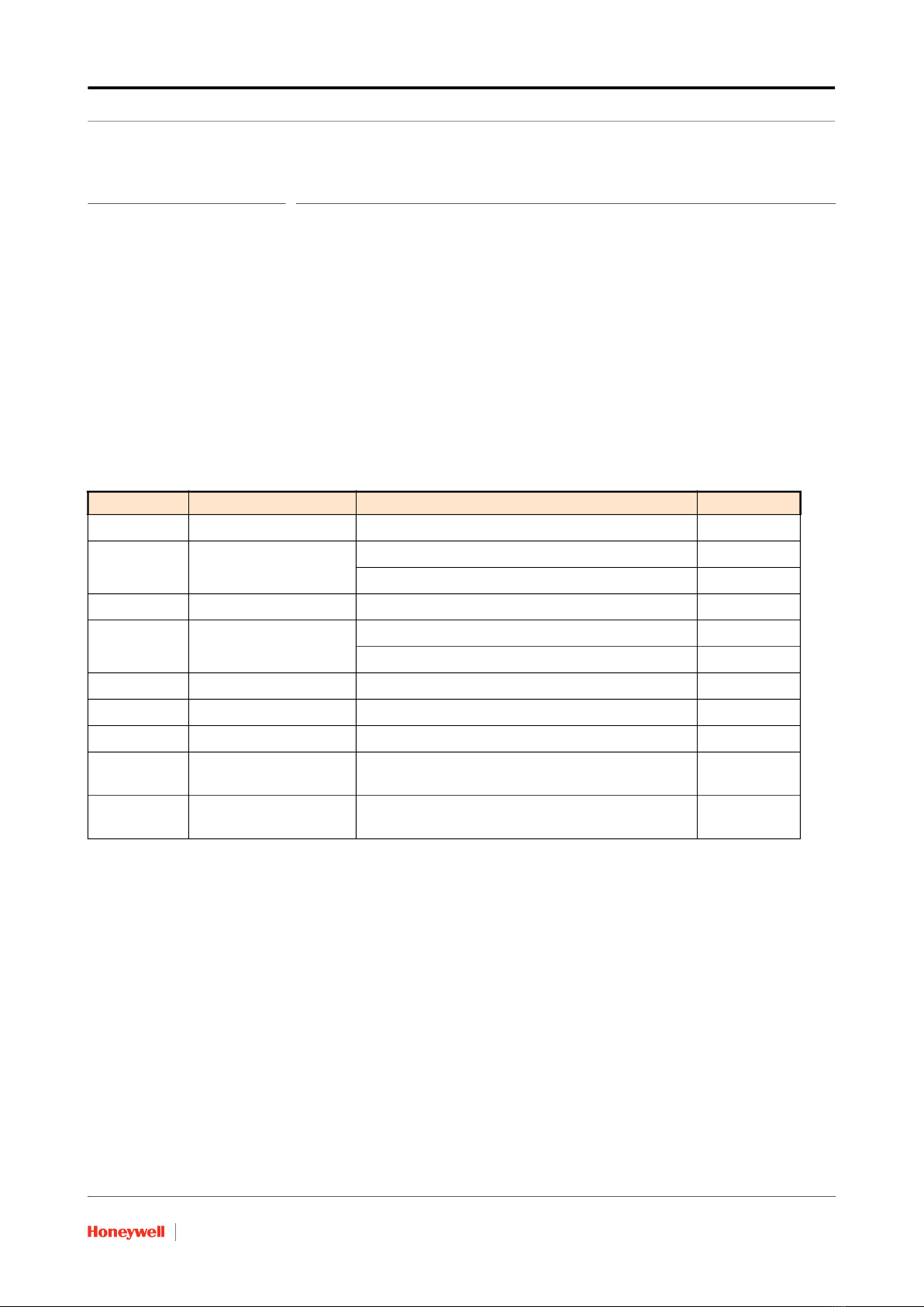
FIGURE 2-3 Fixing the Brackets
2. Mount the CIU 888 on the rack and align the screws to the holes.
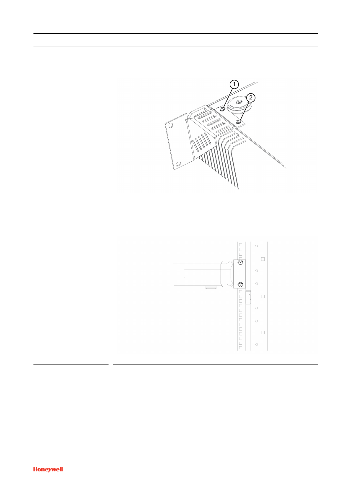
FIGURE 2-4 Align with Rack Holes and tighten the screws
Other manuals for CIU 888
8
Table of contents
Other Honeywell Microphone manuals


