manuals.online logo
Brands
  1. Home
  2. •
  3. Brands
  4. •
  5. Honeywell
  6. •
  7. Plumbing Product
  8. •
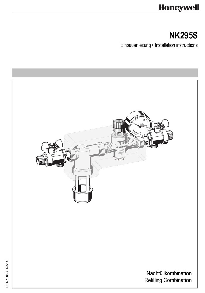
  9. Honeywell NK295 User manual

Honeywell NK295 User manual

EB-NK295 Rev. B
NK295
Nachfüllkombination
Refilling combination
Vanne de remplissage
Combinazione di rabbocco
Einbau-Anleitung • Installation Instruction • Instructions de montage
Istruzioni per il montaggio
EB-NK295-R0404.pmd 07.04.2004, 11:291
Honeywell GmbH 22
22
2MU1H-1226GE23 R0104
1. Sicherheitshinweise ........................... 3
2. Funktionsbeschreibung...................... 3
3. Verwendungsbereich .......................... 5
4. Lieferumfang ....................................... 6
5. Montage ............................................... 7
6. Inbetriebnahme ................................... 9
7. Bedienung ........................................... 9
8. Störung/Fehlersuche ........................ 10
9. Instandhaltung Wartung ................... 11
10.Entsorgung ........................................ 12
11. Zubehör ............................................. 12
D
Inhaltsverzeichnis • Content • Index • Indice
1. Notes de sécurité ................................ 4
2. Description du fonctionnement .......... 4
3. Domaine d'application ........................ 5
4. Description .......................................... 6
5. Montage ............................................... 8
6. Mise en service ................................... 9
7. Exploitation .......................................... 9
8. Pannes/recherche de pannes ......... 10
9. Maintenance ...................................... 11
10. Dépollution ........................................ 12
11. Accessoires ...................................... 12
F
1. Safety guidelines................................. 3
2. Method of Operation ............................ 3
3. Range of application ........................... 5
4. Scope of delivery ................................. 6
5. Assembly ............................................. 7
6. Commissioning .................................. 9
7. Operation ............................................ 9
8. Trouble shooting ............................... 10
9. Maintenance ...................................... 11
10.Disposal............................................ 12
11. Accessories ...................................... 13
GB
1. Note di sicurezza ................................. 4
2. Descrizione del funzionamento.......... 4
3. Campo di applicazione ....................... 5
4. Contenuto della fornitura .................... 6
5. Montaggio ............................................ 8
6. Messa in servizio ................................. 9
7. Modo d’uso .......................................... 9
8. Ricerca avarie ................................... 10
9. Manutenzione .................................... 11
10.Smaltimento ...................................... 12
11. Accessori ........................................... 12
I
EB-NK295-R0404.pmd 07.04.2004, 11:292
MU1H-1226GE23 R0104 33
33
3Honeywell GmbH
2. Funktionsbeschreibung • Method of Operation
Die Nachfüllkombination wird zum automa-
tischen Befüllen und Nachfüllen von
Heizungsanlagen fest mit der Trinkwasser-
versorgung verbunden. Der eingangs-
seitige Systemtrenner basiert auf einem
3-Kammer-System mit Vor-, Mittel- und
Hinterdruckzone. Sinkt der Versorgungs-
druck während des Füllvorgangs unter den
Druck der Heizungsanlage, unterbindet der
Systemtrenner das Rückfließen des
Heizungswassers in die Trinkwasser-
leitung.
Der integrierte Druckminderer arbeitet nach
dem Kraftvergleichssystem. Das heißt,
einer Membrankraft wirkt die Kraft einer
Sollwertfeder entgegen. Der Eingangsdruck
wirkt auf das Ventil weder im öffnenden
noch im schließenden Sinne.
Der Verstellgriff zur Einstellung des ge-
wünschten Hinterdrucks kann auch als
Absperreinrichtung zum Schließen der
Nachfüllkombination verwendet werden.
Der Manometer ermöglicht eine sichere
Kontrolle des Drucks nach Füllen der
Anlage.
D
The NK295 refilling combination is fixed
connected to the drinking water supply for
the automatic filling and refilling of heating
systems.
The inlet backflow preventer is divided into
three zones – inlet, middle and outlet zone.
If during the filling process the inlet
pressure drops below the heating
installation pressure, the backflow preventer
prevents the back flow of heating water into
the drinking water supply. The integral
pressure reducing valve operates by means
of a force equalising system. The force of a
diaphragm operates against the force of an
adjustment spring. The inlet pressure does
not influence either opening or closing of
the valve. Inlet pressure fluctuations
therefore do not influence the outlet
pressure, thus providing inlet pressure
compensation.
The adjustment knob for setting the outlet
pressure can also be used as shutoff tool
for closing the refilling combination.
The pressure gauge permits a safe control
of the pressure during filling process.
GB
1. Sicherheitshinweise • Safety guidelines
1. Benutzen Sie das Gerät
• in einwandfreiem Zustand
• bestimmungsgemäß
• sicherheits- und gefahrenbewusst.
2. Beachten Sie die Einbauanleitung.
3. Lassen Sie Störungen, welche die
Sicherheit beeinträchtigen können
umgehend beseitigen.
4. Das Gerät ist ausschließlich für den in
dieser Einbau-Anleitung genannten
Verwendungsbereich bestimmt. Eine
andere oder darüber hinausgehende
Benutzung gilt als nicht bestimmungs-
gemäß.
5. Alle Montagearbeiten sind durch autori-
siertes Fachpersonal auszuführen.
D
1. Use appliance:
• In good condition
• According to regulations and codes of
practise
• With due regard to safety.
2. Follow installation instructions.
3. Immediately rectify and malfunctions
which may influence safety.
4. The appliance is exclusively for use in
applications detailed in these
installations instructions. Any other use
will not comply with requirements.
5. All assembly operations should be
carried out by competent and authorized
personnel.
GB
EB-NK295-R0404.pmd 07.04.2004, 11:293
Honeywell GmbH 44
44
4MU1H-1226GE23 R0104
La vanne de remplissage est connectée de
façon fixe avec le réseau d’eau potable afin
de permettre un premier remplissage ou
de faire l’appoint de circuits de chauffage.
Le séparateur de fonctions à une voie est
basé sur un système à 3 chambres avec
une zone avant pression, une zone de
pression et une zone de post pression . Si
pression d’alimentation
baisse en dessous de la pression du
chauffage le séparateur de fonctions
empêche un reflux de l’eau du circuit de
chauffage dans la tuyauterie d’eau potable.
Le régulateur détendeur intégré fonctionne
d’après le système de comparaison des
forces en présence. C’est-à-dire qu’un
ressort avec une force de valeur de
consigne s’oppose à la force d’une
membrane. La pression d’alimentation
n’agit sur la soupape ni dans un sens de
fermeture ni dans un sens d’ouverture.
Le capot à ressort réglable pour régler la
post pression peut servir également
comme fermeture de la vanne de remplis-
sage. Le manomètre permet un contrôle
sûr de la pression après le remplissage du
circuit.
F
La combinazione di rabbocco NK295 è
collegata permanentemente all’alimenta-
zione di acqua potabile per il riempimento
ed il rabbocco automatico dei sistemi di
riscaldamento. La valvola antiriflusso
all’ingresso si divide in tre zone, zona
d’entrata, zona centrale e zona d’uscita. Se
la pressione d’alimentazione durante il
processo di riempimento scende al di sotto
della pressione dell’impianto di riscalda-
mento, la valvola antiriflusso impedisce il
riflusso dell’acqua dell’impianto di riscalda-
mento nella condotta dell’acqua potabile. Il
riduttore di pressione integrato lavora con
un sistema di comparazione delle forze. La
forza di una molla di regolazione agisce
contro la forza di un diaframma. La pressione
d’ingresso non influisce sulla valvola né per
l’apertura né per la chiusura. Le fluttuazioni
della pressione d’ingresso non influenzano
pertanto la pressione d’uscita, fornendo in
tal modo una compensazione della pressione
d’ingresso. La manopola di regolazione per
aggiustare la pressione d’uscita può essere
usata anche come dispositivo d’arresto, per
chiudere la combinazione di rabbocco. Il
manometro permette un controllo sicuro della
pressione durante il riempimento dell’impianto.
I
2. Description du fonctionnement • Descrizione del funzionamento
1. Utilisier le dispositif:
• en parfaite condition
• conformémént à son but
• en tenant compte de la sécurité et
d'éventuels dangers.
2. Respecter les instructions de montage.
3. Faire éliminer immédiatement toute
panne qui pourrait compromettre la
sécurité.
4. Le dispositif est uniquement destiné au
domaine d'application mentionné dans
ces instructions de montage. Tout autre
emploi est considéré comme contraire
à sa destination.
5. Tous les travaux de montage seront
exécutés par un personnel compétent
ayant reçu l'autorisation.
F
1. Servirsi del dispositivo
• in una buona condizione
• in conformità del suo scopo
• tenendo in conto la sicurezza e pericoli
eventuali.
2. Osservare le istruzioni per il montaggio.
3. Far eliminare subito ogni panna che
potrebbe compromettere la sicurezza.
4. Il dispositivo è esclusivamente
destinato al campo d'impiego di cui si
tratta in queste istruzioni per il
montaggio. Qualunque altro uso è
considerato come contrario al suo
scopo.
5. Tutti i lavori di montaggio saranno
compiuti da un personale competente
autorizzatoci.
I
1. Notes de sécurité • Note di sicurezza
EB-NK295-R0404.pmd 07.04.2004, 11:294
MU1H-1226GE23 R0104 55
55
5Honeywell GmbH
3. Verwendungsbereich / Technische Daten • Range of application / Technical data
Domaine d'application / Données techniques • Campo di applicazione / Dati tecnici
3.1 Technische Daten
Nachfüllkombination
für geschlossene Hei-
zungsanlagen nach DIN 4751 Teil 2, 3 und 4.
Automatisches Befüllen von Systemen bis
Flüssigkeitskategorie 3 gemäß DIN EN 1717
.
Ermöglicht feste Verbindung mit der
Trinkwasserleitung gemäß DIN EN1717.
Medium Wasser ohne Inhibitoren
Vordruck max.10,0 bar
Eingangsdruck Mindestens 1,5 bar
Einbaulage Waagrecht mit
Ablassventil nach
unten
Betriebstemperatur bis 65 °C
Hinterdruck 1,5 bis 6 bar einstell-
bar
Ablaufrohranschluss HT 40
Anschlüsse 1/2" eingangsseitig
und 1/2"
ausgangsseitig
D
3.1 Données techniques
Vanne de remplissage pour des circuits de
chauffage fermés d’après DIN 4751 parties 2,3
et 4. Remplissage automatiques des
l’installations avec les liquides jusqu'à la classe
de dangerosité 3 d’après DIN EN 1717.
Permet une connexion fixe avec le tuyau d’eau
potable d’après DIN EN 1717.
Fluide de service Eau sans inhiber
Pression d’alimentation max.10,0 bar
Pression d’alimentation minimum 1,5 bar
Position d’installation horizontal avec
soupape de
vidange tournée
vers le bas
Température de service jusqu’à 65°C
Pression secondaire réglable de 1,5
à 6 bars
Connexion tuyau de vidangeHT 40
Connexions 1/2" du côte de l’arrivée
1/2" du côté de la sortie
3.1 Technical Data
Refilling combination for closed heating
systems to DIN 4751 Part 2, 3 and 4.
Automatically filling and refilling of systems
up to liquid category 3 to DIN EN 1717.
According to DIN EN1717 fixed connection
to the drinking water supply permitted.
Medium Water without inhibitors
Inlet pressure max.10,0 bar
Inlet pressure Minimum 1,5 bar
Installation position Horizontal with
discharge valve
downwards
Operating temperature up to 65 °C
Outlet pressure adjustable from
1.5 bar to 6.0 bar
Discharge pipe HT 40
connection
Connections Inlet 1/2"and outlet 1/2"
3.1 Dati tecnici
Combinazione di rabbocco destinata ad impianti
di riscaldamento chiusi secondo la DIN 4751
parti 2,3, e 4. Riempimento automatico delle
disposizione fino categoria liquida 3 secondo
DIN EN 1717. Conformemente alla DIN EN
1717 è consentito il collegamento permanente
con la condotta dell’acqua potabile.
Mezzo acqua con all'esterno
inibisca
Pressione
d’ingresso max.10,0 bar
Pressione d’ingresso minima 1,5 bar
Posizione orizzontale con valvola di
d’installazione scarico
verso il basso
Temperatura di
esercizio fino a 65°C
Pressione d’uscita regolabile da 1,5 fino a
6 bar
Allacciamento tubo
di scarico HT 40
Allacciamenti 1/2" in ingresso
1/2" in uscita
FI
GB
EB-NK295-R0404.pmd 07.04.2004, 11:295
Honeywell GmbH 66
66
6MU1H-1226GE23 R0104
10
4. Lieferumfang • Scope of delivery • Déscription • Contenuto della fornitura
Die Nachfüllkombination besteht aus:
1. Gehäuse
2. Integrierter Schmutzfangsieb
3. Kartuscheneinsatz
4. Ausgangseitiger Rückflussverhinderer
5. Federhaube mit Verstellgriff
6. Druckminderer
7. Absperrung (zum Betätigen Verstellgriff
einsetzen)
8. Anschlussverschraubung
9. Ablaufanschluss
10.Isolierschale
11. Manometer
D
4.1
The refilling combination comprises:
1. Housing
2. Integral strainer
3. Valve cartridge
4. Outlet non-return valve
5 Spring bonnet with adjustment opening
6. Pressure reducing valve
7. Shutoff valve (use adjustment knob as
shutoff tool)
8. Connection fittings
9. Discharge connection
10. Insulation jacket
11. Pressure gauge
GB
La anne de remplissage consiste en:
1. Carter
2. Passoire anti-saletés intégrée
3. Cartouche d’insertion
4. Clapet de non-retour du côte de la sortie
5. Capot à ressort réglage
6. Régulateur détendeur
7. Robinet d’arrêt (met le capot à ressort
réglable comme fermeture)
8. Filetage de connexion
9. Connexion de vidange
10. Enveloppe isolante
11. Manomètre
F
La combinazione di rabbocco comprende:
1. Blocco
2. Filtro integrato
3. Valvola a cartuccia
4. Valvola antiriflusso in uscita
5. Cappotta a molla con manopola di
regolazione
6. Riduttore di pressione
7. Cartuccia d’arresto (usata la manopola
di regolazione come dispositivo d’arresto)
8. Raccordo di collegamento
9. Giunto di scarico
10. Copertura isolante
11. Manometro
I
9
2
5
1
11
3
8
8
4
6
7
EB-NK295-R0404.pmd 07.04.2004, 11:296
MU1H-1226GE23 R0104 77
77
7Honeywell GmbH
1. Thouroughly flush pipework.
2. Dismount insulation jacket
3. Close valve.
4. Install appliance
• Install intergral strainer on inlet.
Do not remove!
•without tension or bending stresses
•in horizontal pipework with the
discharge valve downwards
•with flow in direction of arrow
• at lowest point in the heating system.
5. Connect to discharge.
6. Mount insulation jacket.
• Fit shutoff valves!
• Ensure good accessibility!
• Do not install in positions where
flooding can occur!
• Install in a frost protected and
ventilated location!
• Install discharge pipework which
has adequate capacity!
• Refilling combinations include an
integral strainer no further strainer
necessary!
GB
5.1 5.2
5. Montage • Assembly
2
0
1
4
3
bar
5
4
3
1
1. Rohrleitung gut durchspülen.
2. Isolierschale abnehmen.
3. Ventil schließen.
4. Gerät einbauen
• Schmutzfängersieb eingangsseitig
montieren. Nicht entfernen!
•spannungs- und biegemomentfrei
•waagerecht mit Ablassventil nach
unten
•Durchflussrichtung beachten
• am tiefsten Punkt der Heizungsanlage.
5. An Ablauf anschließen.
6. Isolierschale montieren.
• Absperrventile vorsehen!
• Auf gute Zugänglichkeit achten!
• Nicht in Räumen vorsehen, wo eine
Überflutung möglich ist!
• Einbau in frosicherer,-gut belüfteter
Umgebung!
• Ablaufleitung mit ausreichender •
Kapazität vorsehen!
• In der Nachfüllkombination ist ein
Schmutzfänger integriert, daher
muss kein seperater Schmutzfän-
ger vorgesehen werden!
D
EB-NK295-R0404.pmd 07.04.2004, 11:297
Honeywell GmbH 88
88
8MU1H-1226GE23 R0104
1. Bien rincer la tuyauterie.
2. Enlever l’enveloppe isolante.
3. Fermer le robinet d’arrêt.
4. Installation de la vanne
• installer le passoire anti-saletés
intégrée du côté de entrée.
Ne pas enlever!
• sans tension ni torsion
• horizontal avec soupape de vidange
tournée vers le bas
• veiller au sens d’écoulement de l’eau
• installer à l’endroit le plus bas du
circuit de chauffage.
5. Brancher la sortie.
6. Remonter l’enveloppe isolante.
•Prévoir des robinets d’arrêt!
•Veiller à une bonne accessibilité!
•Ne pas prévoir l’installation dans des
pièces qui sont inondables!
•Montage d’un endroit à l’abri du gel
et bien aéré!
• Prévoir un tuyau de vidange avec une
capacité d’absorption suffisante!
•Une passoire anti-saletés est
intégrée dans la vanne de remplis-
sage donc il est inutile de prévoir des
filtrations séparées!
F
1. Sciacquare bene la tubazione.
2. Rimuovere la copertura isolante.
3. Chiudere la valvola.
4. Montare l’apparecchio
• montare filtro integrato in entrata.
Non ritirarla!
• in modo tale che risulti privo di
tensione e di momenti flettenti
• orizzontalmente, con la valvola di
scarico verso il basso
• facendo attenzione alla direzione del
flusso
• montare l’apparecchio nel punto più
basso dell’impianto di riscaldamento.
5. Allacciarlo allo scarico.
6. Montare la copertura isolante.
• Prevedere la valvola di ritenuta!
• Fare in modo di avere una buona
accessibilità!
• Non prevederlo in ambienti dove è
possibile un allagamento!
• Montare in ambiente che non sia a
rischio di gelo e ben aerato!
• Provvedere ad una condotta di
scarico con sufficiente capacità!
•Nella combinazione per il rabbocco
viene integrato un filtro, in modo da
non dover provvedere ad un filtro
separato!
I
5.1 5.2
5. Montage • Montaggio
2
0
1
4
3
bar
5
4
3
1
EB-NK295-R0404.pmd 07.04.2004, 11:298
MU1H-1226GE23 R0104 99
99
9Honeywell GmbH
7. Bedienung • Operation • Exploitation • Modo d’uso
7.1
7.1 Heizungsanlage befüllen
1. Heizungsanlage entlüften.
2. Ventil öffnen.
3. Heizanlage wird befüllt.
D
7.1 Filling the heating system
1. Vent the heating system.
2. Open the valve.
3. The heating system fills.
GB
2
6. Inbetriebnahme • Commissioning • Mise en Service • Messa in servizio
6.1
1
6.1 Druck einstellen
1. Druck durch Drehen des Griff`s erhöhen
bzw. verringern
Vordruck max. 10,0 bar
Hinterdruck max. 1,5 bis 6 bar
einstellbar
Werkseitig auf 1,5 bar voreingestellt!
D
6.1 Régler la pression
1. Diminuer ou augmenter la pression en
tournant le capot à ressort
Avant pression max. 10,0 bar
Post pression réglable de 1,5 à
max.6 bar
Préréglage usine à 1,5 bar!
F
6.1 Set pressure
1. Raise respectivly reduce pressure by
turning adjustment knob.
Inlet pressure max. 10,0 bar
Outlet pressure adjustable from
1.5 bar to 6.0 bar
Preset to 1.5 bar in the factory!
GB
6.1 Regolazione della pressione
1. Aumentare o diminuire la pressione
girando la manopola
Pressione d’ingresso max. 10,0 bar
Pressione d’uscita regolabile da
1,5 a massimo
6 bar
Regolata in officina su 1,5 bar
I
7.1 Rempli circuit de chauffage
1. Purger le circuit de chauffage.
2. Ouvrir la vanne.
3. Le circuit de chauffage se remplît.
F
7.1 Riempimento dell’impianto di
riscaldamento
1. Ventilare l’impianto di riscaldamento.
2. Aprire la valvola.
3. L’impianto di riscaldamento viene.
I
EB-NK295-R0404.pmd 07.04.2004, 11:299
Honeywell GmbH 1010
1010
10 MU1H-1226GE23 R0104
8. Störung / Fehlersuche • Trouble shooting • Pannes/recherche de pannes
Ricerca avarie
Störung Ursache Behebung
Ablassventil öffnet ohne • Druckschläge im •Vor Systemtrenner einen
ersichtlichen Grund Wassernetz Druckstossdämfer
einbauen
•Schwankender Vordruck •Vor Systemtrenner einen
Druckminderer einbauen
und reinigen
Zu geringer Durchfluss • Eingangsseitiger •Schmutzfänger ausbauen
Schmutzfänger ist ver- und reinigen
stopft
D
I
F
Panne
La soupape de vidange
s’ouvre sans raison
visible
Cause
• Des acoups du réseau d’eau
potable
• La pression d’alimentation
est changeante
Remède
• Installer un amortisseur
d’acoups avant le séparateur
de fonctions
• Installer et nettoyer un
réducteur de pression avant le
séparateur de fonctions
• La passoire anti-saletés
Intégrée est bouchée
Débit trop faible • Enlever et nettoyer la passoire
Fault
Discharge valve opens
without apparent cause
Cause
• Pressure surges in the
water supply
• Fluctuating inlet pressure
Remedy
• Install a surge protector
upstream of the backflow
preventer
• Install a pressure reducer
upstream of the backflow
preventer and clean
• Strainer in inlet side is
clogged
Flow rate too low • Dismantle strainer and clean
Avaria
La valvola di scarico si
apre senza un visibile
motivo
Causa
• Colpi d’ariete
nell’acquedotto comunale
• Pressione d’ingresso
fluttuante
Rimedio
• Installare un ammortizzatore
del colpo d’ariete prima della
valvola antiriflusso
• Installare un riduttore di
pressione prima della valvola
antiriflusso e pulirlo
• Il filtro d’ingresso è ostruito
Flusso troppo basso •Smontare il filtro e pulirlo
GB
EB-NK295-R0404.pmd 07.04.2004, 11:2910
MU1H-1226GE23 R0104 1111
1111
11 Honeywell GmbH
9. Instandhaltung • Maintenance • Maintenance • Manutenzione
Entsprechend DIN 1988 1 x alle 6
Monate!
Nur Fachpersonal!
D
9.1 Schmutzfänger reinigen
1. Ventil schließen.
2. Armatur aus der Rohrleitung entnehmen.
3. Schmutzfänger entnehmen und reinigen.
4. Armatur einbauen.
5. Ventil öffnen.
9.1
1
5
3
D’après DIN 1988 une fois tous les
6 mois!
Uniquement par du personnel
spécialisé!
F
9.1 Nettoyer la passoire anti-saletés
1. Fermer le robinet d’arrêt.
2. Démonter la vanne de la tuyauterie.
3. Enlever la passoire anti-saletés et la
nettoyer.
4. Remonter la vanne.
5. Ouvrir le robinet d’arrêt.
In accordance with DIN 1988, 1 x every
6 months!
Only by trained specialists!
GB
9.1 Clean strainer
1. Close valve.
2. Remove fitting out of the pipeline.
3. Remove strainer and clean.
4. Reinstall fitting.
5. Open valve.
È conforme alla DIN 1988 1 x tutti i 6
mesi!
Solo personale specializzato!
I
9.1 Pulire il filtro
1. Chiudere la valvola.
2. Togliere il raccordo dalla condotta.
3. Rimuovere il filtro e pulirlo.
4. Montare il raccordo.
5. Aprire la valvola.
EB-NK295-R0404.pmd 07.04.2004, 11:2911
Automation and Control Products
Honeywell GmbH Phone: (49) 6261 810
Hardhofweg Fax: (49) 6261 81309 www.honeywell.de/haustechnik
D-74821 Mosbach [email protected] http://europe.hbc.honeywell.com
11. Zubehör • Accessories • Accessoires • Accessori
11
.1
1. Schlauchtülle komplett
mit Schlauchtülle, Verschraubung und
Dichtring
D
1. Un embout de tuyau complet avec
douille de tuyau, écrou et bague
d’étanchéité
F
1. Hose connector, complete with nozzle,
screw-on ring and sealing ring
GB
1. Boccola del tubo flessibile completa
con boccola, collegamento a vite e
anello di tenuta
I
10. Entsorgung • Disposal • Dépollution • Smaltimento
10.1 Entsorgen
Das Gerät besteht aus Messing, Stahl und
Kunststoff.
Beachten Sie, dass die örtlichen
Verschriften zur ordnungsgemäßen
Abfallsverwertung bzw. Beseitigung
eingehalten werden!
D
10.1 Dépollution
La vanne se compose de laiton, d’acier et
de matières plastiques.
Respecter les réglementations
locales quant au tri et l’élimination
des déchets!
F
10.1 Disposal
The appliance is made of brass, steel and
plastic.
Ensure that the local regulations
concerning the correct waste recycling
or disposal are observed!
GB
10.1 Smaltimento
L’apparecchio è fatto di rame, acciaio e
plastica.
Fare in modo che siano osservate le
prescrizioni locali per la rimozione od
il riciclaggio dei rifiuti, secondo le
norme!
I
MU1H-1226GE23 R0404
EB-NK295-R0404.pmd 07.04.2004, 11:2912

Other Honeywell Plumbing Product manuals

Honeywell BA295D-1/2AS User manual

Honeywell

Honeywell BA295D-1/2AS User manual

Honeywell BA295STN-3/4WH User manual

Honeywell

Honeywell BA295STN-3/4WH User manual

Honeywell BA300 Series User manual

Honeywell

Honeywell BA300 Series User manual

Honeywell BA195 miniBA User manual

Honeywell

Honeywell BA195 miniBA User manual

Honeywell V4710 User manual

Honeywell

Honeywell V4710 User manual

Honeywell NK295S User manual

Honeywell

Honeywell NK295S User manual

Honeywell BA295S User manual

Honeywell

Honeywell BA295S User manual

Honeywell V4043H User manual

Honeywell

Honeywell V4043H User manual

Honeywell T104 User manual

Honeywell

Honeywell T104 User manual

Honeywell VT117E User manual

Honeywell

Honeywell VT117E User manual

Honeywell BA295 Compact User manual

Honeywell

Honeywell BA295 Compact User manual

Honeywell NK300S User manual

Honeywell

Honeywell NK300S User manual

Honeywell BA295D-3/4WHD User manual

Honeywell

Honeywell BA295D-3/4WHD User manual

Honeywell V4770 User manual

Honeywell

Honeywell V4770 User manual

Honeywell CA195 User manual

Honeywell

Honeywell CA195 User manual

Popular Plumbing Product manuals by other brands

KWC F3ET1010 Installation and operating instructions

KWC

KWC F3ET1010 Installation and operating instructions

Hans Grohe AXOR MyEdition 230 47020 1 Series Installation/User Instructions/Warranty

Hans Grohe

Hans Grohe AXOR MyEdition 230 47020 1 Series Installation/User Instructions/Warranty

American Standard CORNICE 0611 INSTALLATION INSTRUCTIONS CARE AND MAINTENANCE

American Standard

American Standard CORNICE 0611 INSTALLATION INSTRUCTIONS CARE AND MAINTENANCE

ShowHouse Show House TS4712 Series Specification sheet

ShowHouse

ShowHouse Show House TS4712 Series Specification sheet

American Standard Hampton T970.702 installation instructions

American Standard

American Standard Hampton T970.702 installation instructions

Franke XINX140 Installation and operating instructions

Franke

Franke XINX140 Installation and operating instructions

Trendwood PATIO L THERMO SAUNA installation manual

Trendwood

Trendwood PATIO L THERMO SAUNA installation manual

Kallista P23010 installation instructions

Kallista

Kallista P23010 installation instructions

American Standard Heritage Bidet 5034 installation instructions

American Standard

American Standard Heritage Bidet 5034 installation instructions

Spectrum EFHS-PK-10-3/4 Installation & operation guide

Spectrum

Spectrum EFHS-PK-10-3/4 Installation & operation guide

Laufen LIS CW1 H894660 manual

Laufen

Laufen LIS CW1 H894660 manual

Gessi ORIGINI 66036 manual

Gessi

Gessi ORIGINI 66036 manual

Helvex LV ELIPSIS installation guide

Helvex

Helvex LV ELIPSIS installation guide

Marco MIX 1000879FB instruction manual

Marco

Marco MIX 1000879FB instruction manual

Spectrum Brands Pfister Park Avenue LG49-FE0 Quick installation guide

Spectrum Brands

Spectrum Brands Pfister Park Avenue LG49-FE0 Quick installation guide

Helvex Liquida TV302-1.5 installation guide

Helvex

Helvex Liquida TV302-1.5 installation guide

ZUCCHETTI ISY ZD2699 installation instructions

ZUCCHETTI

ZUCCHETTI ISY ZD2699 installation instructions

Bristan CRAZE CRZ2 SHXDIVCTFF C Installation instructions & user guide

Bristan

Bristan CRAZE CRZ2 SHXDIVCTFF C Installation instructions & user guide

manuals.online logo
manuals.online logoBrands
  • About & Mission
  • Contact us
  • Privacy Policy
  • Terms and Conditions

Copyright 2025 Manuals.Online. All Rights Reserved.