manuals.online logo
Brands
  1. Home
  2. •
  3. Brands
  4. •
  5. Honeywell
  6. •
  7. Relay
  8. •
  9. Honeywell Farenhyt Series User manual

Honeywell Farenhyt Series User manual

INSTALLATION AND MAINTENANCE INSTRUCTIONS
BEFORE INSTALLING
This information is included as a quick reference installation guide. Refer to
the appropriate Honeywell Farenhyt series control panel installation manual
for detailed system information. If the modules will be installed in an existing
operational system, inform the operator and local authority that the system
will be temporarily out of service. Disconnect power to the control panel be-
fore installing the modules.
NOTICE: This manual should be left with the owner/user of this equipment.
GENERAL DESCRIPTION
The IDP-Relay is intended for use in intelligent, two-wire systems where
the individual address of each module is selected using the built-in rotary
switches. It allows a compatible control panel to switch discrete contacts
by code command. The relay contains two isolated sets of Form-C contacts,
which operate as a DPDT switch and are rated in accordance with the table in
the manual. Circuit connections to the relay contacts are not supervised by the
module. The module also has a panel controlled LED indicator.
COMPATIBILITY REQUIREMENTS
To ensure proper operation, this module shall be connected to a compat-
ible Honeywell Farenhyt series system control panel (list available from
Honeywell).
SPECIFICATIONS
Normal Operating Voltage: 15 to 32 VDC
Maximum Current Draw: 6.5 mA (LED on)
Average Operating Current: 230μA direct poll; 255μA group poll
EOL Resistance: Not used
Temperature Range: 32˚F to 120˚F (0˚C to 49˚C)
Humidity: 10% to 93% Non-condensing
Dimensions: 4.675" H x 4.275" W x 1.4" D (Mounts to a 4" square by 21/8" deep box.)
Accessories: SMB500 Electrical Box
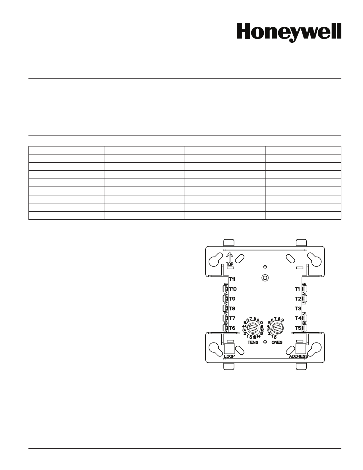
FIGURE 1. CONTROLS AND INDICATORS:
C1071-00
MOUNTING
The IDP-Relay mounts directly to 4-inch square electrical boxes (see Figure
2A). The box must have a minimum depth of 21/8inches. Surface mounted
electrical boxes (SMB500) are available from Honeywell. The module can also
mount to the SK-DUCT or DNR(W) housing.
RELAY CONTACT RATINGS:
CURRENT RATING MAXIMUM VOLTAGE LOAD DESCRIPTION APPLICATION
2 A 25 VAC PF = 0.35 NON-CODED
3 A 30 VDC RESISTIVE NON-CODED
2 A 30 VDC RESISTIVE CODED
0.46 A 30 VDC (L/R = 20MS) NON-CODED
0.7 A 70.7 VAC PF = 0.35 NON-CODED
0.9 A 125 VDC RESISTIVE NON-CODED
0.5 A 125 VAC PF = 0.75 NON-CODED
0.3 A 125 VAC PF = 0.35 NON-CODED
I56-3601-005
12 Clintonville Road, Northford, CT 06472-1610
Phone: 203-484-7161 Fax: 203-484-7118
www.Farenhyt.com
IDP-Relay
1 I56-3601-005
04-21
Farenhyt™ Series
WARNING
All relay switch contacts are shipped in the standby state (open) state, but may have transferred to the activated (closed) state during shipping. To ensure that
the switch contacts are in their correct state, modules must be made to communicate with the panel before connecting circuits controlled by the module.
FIGURE 3. RELAY MODULE WIRING DIAGRAM:
MODULE
FROM PANEL OR
(+)
(–)
TO NEXT
(+)
(–)
DEVICE
(+)
(–)
CONTROL
CONNECT MODULES TO LISTED COMPATIBLE
RELAY COMMON 1
RELAY COMMON 2
NORMALLY CLOSED 1
NORMALLY OPEN 2
NORMALLY CLOSED 2
MODULE DOES NOT SUPERVISE CONTROLLED CIRCUITS
NORMALLY OPEN 1
CONTROL PANELS ONLY
PREVIOUS DEVICE
SIGNAL LINE CIRCUIT (SLC)
32 VDC MAX.
TWISTED PAIR
IS RECOMMENDED
UNUSED
*NOTE: ANY FAULT IN THE POWER SUPPLY IS LIMITED TO THAT ZONE AND DOES NOT RESULT IN A FAULT IN A SEPARATE ZONE.
IF ANY WIRING TO TERMINALS 4 – 10 IS NONPOWER
LIMITED, THE CB500 BARRIER IS REQUIRED. THE CB500
INCLUDES A NONPOWER LIMITED LABEL, WHICH MUST
BE PLACED OVER THE POWER LIMITED TERMINAL
INFORMATION ON THE NAMEPLATE LABEL.
C0946-00
FIGURE 2A. MODULE MOUNTING FIGURE 2B:
WITH BARRIER:
WIRING
NOTE: All wiring must conform to applicable local codes, ordinances, and reg-
ulations. When using control modules in nonpower limited applications, the
CB500 Module Barrier must be used to meet UL requirements for the separa-
tion of power-limited and nonpower-limited terminals and wiring. The barrier
must be inserted into a 4" × 4" × 21/8" junction box, and the control module
must be placed into the barrier and attached to the junction box (Figure 2A).
The power-limited wiring must be placed into the isolated quadrant of the
module barrier (Figure 2B).
1. Install module wiring in accordance with the job drawings and appropri-
ate wiring diagrams.
2. Set the address on the module per job drawings.
3. Secure module to electrical box (supplied by installer), as shown in
Figure 2A.
Wire should be stripped to the appropriate length (recommended strip length
is 1/4" to 3/8"). Exposed conductor should be secured under the clamping plate
and should not protrude beyond the terminal block area. Caution: Do not loop
wire under terminals. Break wire run to provide supervision of connections.
NOTE: All references to power limited represent “Power Limited (Class 2)”.
C1070-00
2 I56-3601-005
©2017 Honeywell. 04-21
Farenhyt™ is a trademark of and Honeywell®is a registered trademark of Honeywell International, Inc.

Other manuals for Farenhyt Series

10

This manual suits for next models

1

Other Honeywell Relay manuals

Honeywell AQUASTAT L8124A User manual

Honeywell

Honeywell AQUASTAT L8124A User manual

Honeywell ADEMCO 5800RL Assembly instructions

Honeywell

Honeywell ADEMCO 5800RL Assembly instructions

Honeywell RP470A User manual

Honeywell

Honeywell RP470A User manual

Honeywell X47 User manual

Honeywell

Honeywell X47 User manual

Honeywell 7800 SERIES User manual

Honeywell

Honeywell 7800 SERIES User manual

Honeywell R4343D User manual

Honeywell

Honeywell R4343D User manual

Honeywell R4343D User manual

Honeywell

Honeywell R4343D User manual

Honeywell Aquastat L8148A Operation manual

Honeywell

Honeywell Aquastat L8148A Operation manual

Honeywell NOTIFIER FW-RM User manual

Honeywell

Honeywell NOTIFIER FW-RM User manual

Honeywell NOTIFIER FRM-1 User manual

Honeywell

Honeywell NOTIFIER FRM-1 User manual

Honeywell Notifier SKBR3N User manual

Honeywell

Honeywell Notifier SKBR3N User manual

Honeywell SILENT KNIGHT IDP-Relay User manual

Honeywell

Honeywell SILENT KNIGHT IDP-Relay User manual

Honeywell HPSR103 User manual

Honeywell

Honeywell HPSR103 User manual

Honeywell 301RW User manual

Honeywell

Honeywell 301RW User manual

Honeywell Silent Knight SK-Relay User manual

Honeywell

Honeywell Silent Knight SK-Relay User manual

Honeywell R841C-E User manual

Honeywell

Honeywell R841C-E User manual

Honeywell RM7897A User manual

Honeywell

Honeywell RM7897A User manual

Honeywell SeqLED E SET-30 User manual

Honeywell

Honeywell SeqLED E SET-30 User manual

Honeywell TRADELINE R182J User manual

Honeywell

Honeywell TRADELINE R182J User manual

Honeywell 7800 SERIES User manual

Honeywell

Honeywell 7800 SERIES User manual

Honeywell 7800 SERIES User manual

Honeywell

Honeywell 7800 SERIES User manual

Honeywell EC7895A User manual

Honeywell

Honeywell EC7895A User manual

Honeywell 7800 SERIES RM7895A Operation manual

Honeywell

Honeywell 7800 SERIES RM7895A Operation manual

Honeywell 7800 SERIES User manual

Honeywell

Honeywell 7800 SERIES User manual

Popular Relay manuals by other brands

ZIEHL SPI1021 operating manual

ZIEHL

ZIEHL SPI1021 operating manual

Ametek UPLC CU44-VER04 Applications manual

Ametek

Ametek UPLC CU44-VER04 Applications manual

Devantech dS2824 user manual

Devantech

Devantech dS2824 user manual

Intelligent Appliance IA-3178-U2i user manual

Intelligent Appliance

Intelligent Appliance IA-3178-U2i user manual

Entes DG-10 quick start guide

Entes

Entes DG-10 quick start guide

Pilz PNOZ s20 operating manual

Pilz

Pilz PNOZ s20 operating manual

GMI D5097S-107 instruction manual

GMI

GMI D5097S-107 instruction manual

Schweitzer Engineering Laboratories SEL-487B-2 manual

Schweitzer Engineering Laboratories

Schweitzer Engineering Laboratories SEL-487B-2 manual

GE 239 instruction manual

GE

GE 239 instruction manual

Bender IOM441-S manual

Bender

Bender IOM441-S manual

F&F FW-R2D manual

F&F

F&F FW-R2D manual

Contrel ELR-D2-V instruction manual

Contrel

Contrel ELR-D2-V instruction manual

Aiphone RY-18L instructions

Aiphone

Aiphone RY-18L instructions

MULTISPAN MI-632 Installation guidelines

MULTISPAN

MULTISPAN MI-632 Installation guidelines

Emirel W 19 quick start guide

Emirel

Emirel W 19 quick start guide

Tyco HVR800 manual

Tyco

Tyco HVR800 manual

ABB REX 521 Operator's manual

ABB

ABB REX 521 Operator's manual

M.C. MILLER JR-2 operating manual

M.C. MILLER

M.C. MILLER JR-2 operating manual

manuals.online logo
manuals.online logoBrands
  • About & Mission
  • Contact us
  • Privacy Policy
  • Terms and Conditions

Copyright 2025 Manuals.Online. All Rights Reserved.