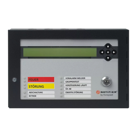
Honeywell NOTIFIER LCD6000T User manual

LCD6000T
Repeater Panel
Programming
And installation
manual

LCD6000 Installation manual INDEX
LCD6000_manu-inst Doc. M-184.1-LCD6000T-ENG Rev A.1 NOTIFIER ITALIA
INDEX
GENERALDESCRIPTION 1
OPERATION 1
TECHNICAL SPECIFICATION 1
SIZE FOR WALL ASSEMBLY 2
CONTROLSONTHEFRONTPANEL 3
SIGNALLINGS ON THE FRONY PANEL 4
USER INTERFACE DESCRIPTION 5
CONDITION WITH ALARM ZONE EVENT 6
CONDITION WITH BREAKDOWN ZONE EVENTS 7
CONDITION WITH SYSTEM BREAKDOWN EVENT 8
DISPLAY OF EXCLUDED ZONES AND POINTS 8
SENSOR 9
ZONES 9
TEST 10
LOCALPROGRAMMING 10
ADDRESS 11
BUZZERVOLUME 11
INSTALLATION IN “MULTI POINT” CONFIGURATION (DAISY CHAIN) 12
SCREENED CABLE AND EARTH CONNECTION 12
LCD-6000T BOARD TOPOGRAPHY 13
CN1TERMINALBLOCK 14
ELECTRICALFEATURES 14
PROGRAMMING OF THE MMT AND IIG4-N 15
TECHNOLOGICAL DEVICE PROGRAMMINGTHROUGH TYPE-ID “TEC3” or “TEC2” 18
TECHNOLOGICALRANGES 22
PROGRAMMING OF THE ECHNOLOGIAL RANGES 22

LCD6000 Installation manual PAGE - 1
LCD6000_manu-inst Doc. M-184.1-LCD6000T-ENG Rev A.2 NOTIFIER ITALIA
NOTE: Do not try to install the LCD-6000T panel without reading this manual.
ATTENTION: This manual refers to all functions available in the software revision
indicated on the cover.
DETECTION SYSTEM LIMITS
An alarm or fire detection system can be very useful for the prompt warning of any dangerous event, such as
a fire, a robbery or a simple burglary, in some cases it can automatically manage events (transmission of
messages for room evacuation, automatic fire-extinguishing, TVCC system interface, access route or door
blockage, automatic warning to authorities, etc.), but in any case, it does not ensure protection against
damages to propriety or damages deriving from fires or robberies). Moreover, each system may not properly
operate if it is not installed and maintained according to the manufacturer’s instructions.
PRECAUTIONS
These instructions contain procedures to be followed in order to avoid damages to
equipment. It is assumed that the user of this manual has performed a training
course and that he knows the applicable rules in force.
The system and all its components must be installed in an environment having the
following features:
Temperature: -5 °C ¸ +40 °C.
Humidity: 10 % - 93 % (without condensation).
Peripheral devices (sensors, etc.) which are not perfectly compatible with the
control unit may cause damages to the same control unit, and a bad operation of
the system in any moment. Therefore, it is essential to only use material which is
guaranteed by NOTIFIER and is compatible with its own control units.
Please consult NOTIFIER Technical Service for any doubt.
This system, like all solid state components, may be damaged by induced
electrostatic voltages: handle the boards holding their edges and do not touch the
electronic components.
An appropriate earthing connection ensures, in any case, a sensitivity reduction to
disturbances.
Please consult NOTIFIER Technical Service if you cannot solve installation
problems.
Any electronic system does not operate if it is not powered.
If power supply from the mains fails, the system ensures its operation through
battery, but only for a limited period of time.
During the system planning phase, take into account the autonomy required to
appropriately dimension the power supply and batteries.
Skilled personnel shall periodically check the state of batteries.
Disconnect the MAINS and the batteries BEFORE removing or inserting any board.
Disconnect ALL power supply sources from the control unit, BEFORE performing
any servicing.
The control unit and the connected devices (sensors, modules, annunciators, etc.)
may be damaged, if a new board is inserted or removed, or if the powered cables
are connected.
The most common cause for malfunctioning is inappropriate maintenance.
Take special care of these aspects since you start the system planning phase; this
will facilitate future servicing and will reduce cost.
This device is marked CE to certify it is in conformity with the European Community Directives:
Electromagnetic Compatibility Directive 89/336/EEC (and the directive 92/23/EEC)
Low Voltage Directive 73/23/EEC
National Rules
PAGE - 2 Installation manual LCD6000
NOTIFIER ITALIA Doc. M-184.1-LCD6000T-ENG Rev A.2 LCD6000_manu
This device must be installed and must operate in accordance with these instructions and
with the rules in force in the installation place.
GENERAL DESCRIPTION
DESCRIPTION
LCD-6000T is a panel for the management of gas detection devices or Technological devices having
a 4-20mA interface which are installed in AM-2000; AM-4000; AM-6000 control units.
Up to 16 LCD-6000T can be connected to a single control unit as a terminal function.
The LCD-6000T panel indicates all signallings coming from the 4-200 mA interface modules and allows to
perform the following functions :
EVENT RECOGNITION.
ALARM RESET.
DISPLAY OF EXCLUDED POINTS AND ZONES
DISPLAY OF ZONES AND POINTS UNDER TEST
OPERATION
It needs the local programming to assign the peripheral address
The LCD-6000T panel displays time, date and personalized messages coming from AM series control
units.
On each LCD-6000T control panel, can be independently performed the functions relevant to the keys:
- Buzzer Silencing and Alarm Reset.
- Moreover, it allows to display the event lists subdivided into:
- Alarms, breakdowns, System breakdowns.
Technical specifications:
Microprocessor system
LCD display 320 x 240 points
Keyboard with keys dedicated to specific functions: Buzzer Silencing, Reset.
Serial lines :
- 1 RS 485 interface
Power supply
10 ÷ 30Vcc
Connections
- 2 power supply cables
- 3 cables for serial connection
Mechanical features:
The LDC6000 panel mechanical features are suitable for wall installations.
Sizes 180mm (L) x 168mm (H) x 55mm (P)
Protection grade : IP 20
Operation temperature : from -5 °C to +40 °C
PANEL LCD-6000-N
LCD-6000-T LCD-6000A Max numbers LCD
installable
AM-2000N max 12 max 10 16
AM-4000 max 16 max 14 22
AM-4000G max 16 LCD-6000-T NO 16
AM-6000N max 16 max 16 24

LCD6000 Installation manual PAGE - 3
LCD6000_manu-inst Doc. M-184.1-LCD6000T-ENG Rev A.2 NOTIFIER ITALIA
INSTALLATION
Sizes for wall assembly
.
The panel can be wall- installed through 4 self-
blocking cleats (masonry walls) or self-tapping
screws (prefabricated panels, etc.)
The screws used must have a maximum diameter of
5 mm. It is recommended not to install the panel
near heat sources (radiators, etc.)
Fastening screws max 5 mm
.
Fasten the incoming
cable with a cable-
fastening strip
Connect the incoming cable to CN1 extractable terminal block
Screws fastening the front panel to the base

PAGE - 4 Installation manual LCD6000
NOTIFIER ITALIA Doc. M-184.1-LCD6000T-ENG Rev A.2 LCD6000_manu
CONTROLS ON THE FRONT PANEL
PASSWORD LEVEL 2
To enter the password input is sufficient to hold the reset button, or, press key and then, with the arrow
keys select “local programming”.
With the arrow keys select the first figure, press "ENTER" to confirm and move to the inclusion of
the next figure.
Repeat this action until a final digit.
The level 2 password by default is 22222
SIGNALLINGS ON THE FRONT PANEL
PRE-ALARM1 (Red):
It flashes if there is at least a technological type device in un-recognized Pre-alarm-1
condition (the P1 threshold is set in the control unit on the devices which are programmed
with Type-ID “TEC2” or “TEC3”).
It is permanently lit if all Pre-alarm-1 events have been recognized.
PRE-ALARM2 (Red):
It flashes if there is at least a technological type device in un-recognized Pre-alarm -2
condition (the P2 threshold is set in the control unit on the devices which are programmed
with Type-ID “TEC2” or “TEC3”).
It is permanently lit if all Pre-alarm-2 events have been recognized.
ALARM (Red):
It flashes if there is at least a technological type device in un-recognized Pre-alarm-2
condition (the AL threshold is set in the control unit on the devices which are programmed
with Type-ID “TEC2” or “TEC3”). It is permanently lit if all Alarm events have been
recognized
BUZZER SILENCING: by pressing this key, you
can silence the LCD6000T panel buzzer and you can
perform the RESET control.
RESET: by pressing this key, you can cancel
the memory of current alarms or breakdowns of
points. It deactivates the sirens and switches off
all light signallings of the alarm sensors.
To perform this operation the level 2 password
must be known.
ARROWS: selection keys.
LISTS: this key has a double operating mode:
1) the simple pressure of this key allows entering the adjacent
folders (displays)
2) in case of alarm zone or breakdown zone events, it allows to
display the list of each alarm or breakdown point
MENU: by pressing this key the user can access both
the LDC6000T panel programming menu and the
display functions of the excluded points and zones.

LCD6000 Installation manual PAGE - 5
LCD6000_manu-inst Doc. M-184.1-LCD6000T-ENG Rev A.2 NOTIFIER ITALIA
BREAKDOWN (Yellow):
It flashes if there is any type of breakdown and it has not been recognized.
It is permanently lit if all breakdowns have been recognized
VOLTAGE (Green):
It is permanently lit if the LCD6000 T Panel is powered
Exclusion (Yellow):
1. For fire alarm control panel AM-2000N / AM-4000N / AM-6000N
Lit when one point or technologic zone are excluded
2. For AM-4000G
Lit when the following devices are excluded:
Sensor
Zone
Siren output
Immediately activation
!

PAGE - 6 Installation manual LCD6000
NOTIFIER ITALIA Doc. M-184.1-LCD6000T-ENG Rev A.2 LCD6000_manu
U
US
SE
ER
R
I
IN
NT
TE
ER
RF
FA
AC
CE
E
D
DE
ES
SC
CR
RI
IP
PT
TI
IO
ON
N
N.B.
LCD-6000T is a panel for the management of installed Technological devices having 4-20mA (MMT or
IIG4-N) interface.
The technologica l point programming must be perf ormed on the control unit ( refer t o c hapter
Programming of MMT and IIG4-Ntechnological devices contained in this manual).
Normal condition
The following is displayed when there are no anomaly conditions (alarms or breakdowns) on the LCD6000T
panel:
Date - Hour
Alarm zone
counter
Breakdown
zone counter
System breakdown
counter
Excluded zone
counter
Icon to signal the state of the serial
connection
In case of anomaly on the serial
connection the following state
icon is displayed:
Icon to signal the Panel state.
In the state of alarm and breakdown absence there is the symbol of NOTIFIER mark.
In the presence of excluded points or zones an exclamation point is displayed( !).
In the presence of pre-alarms or alarms there is the symbol .
In the presence of breakdowns there is the Triangle symbol
N.B. The alarm state prevails if alarms and breakdowns are simultaneously present on the panel.
State of the RS485 serial connection
In case of anomaly on the serial connection
there is the “OFF LINE” signaling

LCD6000 Installation manual PAGE - 7
LCD6000_manu-inst Doc. M-184.1-LCD6000T-ENG Rev A.2 NOTIFIER ITALIA
C
Co
on
nd
di
it
ti
io
on
n
w
wi
it
th
h
a
al
la
ar
rm
m
z
zo
on
ne
e
e
ev
ve
en
nt
ts
s
The following is displayed when there is an alarm zone in the control unit.
Through the arrow keys you can scroll the alarm zone list.
In case of several alarm zones to display the alarm devices in a specific zone, the list zone must be scrolled
until the required zone is in the display area of the first event.
By pressing the key the list of alarm points of the selected zone can be accessed.
Through the arrow keys the list of alarm devices can be scrolled.
Alarm zone counter
Date and time of
the first event of
zone alarm
First alarm zone
Text programmed
for the zone
Latest alarm zone
Programmed text for
the zone
Date and time of
the latest zone
alarm event
Device in alarm
Programmed text for
the device
TYPE-ID
Display Area of
the first event
Display area of
the latest event

PAGE - 8 Installation manual LCD6000
NOTIFIER ITALIA Doc. M-184.1-LCD6000T-ENG Rev A.2 LCD6000_manu
Condition with breakdown zone events
The following is displayed when the control unit is in breakdown zone condition
The breakdown events are also initially displayed for zone
Through the arrows keys you can scroll the breakdown zones
In case of several breakdown zones to display the devices in a specific zone, the zone list must be scrolled
until the chosen zone is in the display area of the first event.
By pressing the key for some seconds you can access the detailed list of the selected zone breakdown
points. you can scroll the failed device list.
Breakdown
zone
Text
prograrmmed for
Failed device
S = sensor
M = module
Programmed text
for the device
TYPE-ID
Breakdown zone
counter
Date and time
of the first
zone
breakdown
event
Date and time of the
latest alarm zone
event
Display area of
the first event

LCD6000 Installation manual PAGE - 9
LCD6000_manu-inst Doc. M-184.1-LCD6000T-ENG Rev A.2 NOTIFIER ITALIA
Condition with System breakdown event
The following is displayed when there is a system anomalous condition at the control unit.
Acknowledge Outputs
NB: This function is enabled only for the AM4000G
For acknowledge outputs activated on alarm see the following procedure
1. Press the key menu to display the following
2. select the item “acknowledge output siren ” and press the key to access the menu
System breakdown
counter
Date and time of the
event
Description of the
System Breakdown

PAGE - 10 Installation manual LCD6000
NOTIFIER ITALIA Doc. M-184.1-LCD6000T-ENG Rev A.2 LCD6000_manu
3. enter the level 2 password
4. After entering the password to display the following
5. Press the key to confirm.
Display of excluded zones and points
To access the display functions of the excluded zones or points follow these instructions:
6. Press the key to display the following
7. Through the arrow keys select the item “Exclusion” and press the key to access the menu
.
Sensors
By selecting the item “Sensors” and confirming the choice the following display is accessed:
Excluded sensor number
counter
Excluded zone number
counte
r

LCD6000 Installation manual PAGE - 11
LCD6000_manu-inst Doc. M-184.1-LCD6000T-ENG Rev A.2 NOTIFIER ITALIA
Zones
By selecting the item “Zone” and confirming the choice the following is displayed:
Use the arrow keys to
scroll the excluded point list
Press the key to
return to the previous menu
It indicates the displayed
Exclusion event number It indicates the Excluded point
total number
Point indication
Name assigned to
the point
Name of the
zone assigned
to the point
Use the arrow keys
to scroll the excluded Zone list
Press the key
to return to the
previous menu
Indication of the
Excluded zone
Number
Zone number
It indicates the displayed
Exclusion event number. It indicates the total number of
Excluded zones

PAGE - 12 Installation manual LCD6000
NOTIFIER ITALIA Doc. M-184.1-LCD6000T-ENG Rev A.2 LCD6000_manu
TEST
From the Main Menu through the arrow keys select the item “TEST” and press the key
to access the display menu of the test zone devices.
The following menu is displayed:
To display the lists of the devices under Test (Sensors or Zones) select through the arrow keys the
required item, press the key to confirm the selection.
LOCAL PROGRAMMING
Press the key from the state window and subsequently through the arrow keysselect the item
“Local Prog” and
press the key to access the programming menu, where the user can perform the initial configuration of
the LCD-6000T panel and make possible changes
The following menu is displayed :
Use the arrow keys to
select the function to be
changed and press the Lists
key to confirm and
access the function
Number counter of devices under test
Number Counter of zone under test

LCD6000 Installation manual PAGE - 13
LCD6000_manu-inst Doc. M-184.1-LCD6000T-ENG Rev A.2 NOTIFIER ITALIA
Where:
Address
Select the item “Address” to assign the peripheral number to the LCD-6000T terminal device.
Use the arrow keys to select the peripheral number and press the Lists key to confirm the datum. The useful
addresses to be assigned to the LCD-6000T are from 1 ÷ 16
The address assigned to the terminal device is unique, therefore it is not possible to have several
terminals with the same address.
Buzzer volume
By selecting the item “Buzzer Volume” through the arrow keys and pressing the Lists key to confirm, the user
can program the buzzer volume in case of alarm or breakdown.
Test Led
By selecting the item “Test Led” through the arrow keys and pressing the Lists key to confirm, the panel
performs the lamp-test function.
Test LCD
By selecting the item “Test LCD” through the arrow keys and pressing the Lists key to confirm, the panel
performs the display test.

PAGE - 14 Installation manual LCD6000
NOTIFIER ITALIA Doc. M-184.1-LCD6000T-ENG Rev A.2 LCD6000_manu
RS.485 serial Line
The LDC6000 panel is connected to the control unit through the RS.485 serial line.
The RS.485 line must be installed in “MULTI-POINT” configuration (daisy chain).
Each peripheral must be programmed with an address from 1 16. Refer to the installation manuals of each peripheral.
Installation in “Multi-Point” configuration (Daisy Chain) separate power
Connect two wires from the RS.485
terminals of the control unit (LIN+
and LIN- terminals) to the
correspondent terminals of the first
device on the line.
Continue the wiring from the first
device to the subsequent one, and
so on.
Install the line end resistance (120-
150, 0.5W) on both the control
unit terminals and the terminals of
the last line device.
The maximum admitted length from
the control unit to the last device is
1.5km.
Use screened cable of appropriate
section 9574 or 9575 Belden type
AM-4000
17
+24V GND
EOL= 120
LCD-6000T
16
11 1 2 3 4
+24V GND EOL= 120
3130
LCD-6000T
1 2 3 4 5 5
GND+24V
A
M-4000
17
+24V GND
EOL= 120
LCD-6000T
1611 1 2 3 4
+24V GND EOL= 120
LCD-6000
T
1
2
3 4 5 5
6 7 6 7
A
M-6000
9
+24V GND
EOL= 120
LCD-6000T
8
7 1 2 3 4
+24V GND EOL= 120
LCD-6000
T
1
2
3 4 5 5
6 7 6 7
Typical RS.485 Multi-point connection (Daisy Chain) separate power
Note: Terminals 6 and 7 are not used on the LCD600T panel

LCD6000 Installation manual PAGE - 15
LCD6000_manu-inst Doc. M-184.1-LCD6000T-ENG Rev A.2 NOTIFIER ITALIA
Installation in “Multi-Point” configuration (Daisy Chain) –Shared Power
Connect two wires from the RS.485
terminals of the control unit (LIN+
and LIN- terminals) to the
correspondent terminals of the first
device on the line.
Continue the wiring from the first
device to the subsequent one, and
so on.
Install the line end resistance (120-
150, 0.5W) on both the control
unit terminals and the terminals of
the last line device.
The maximum admitted length from
the control unit to the last device is
1.5km.
Use screened cable of appropriate
section 9574 or 9575 Belden type
GND+24V
AM- 2 000
13
EOL= 120
LCD-6000T
12
7 1 2 3 4
EOL= 120
2322
LCD-6000T
1 2 3 4 5 5
6 7 6 7
GND+24V
AM- 4 000
17
EOL= 120
LCD-6000T
16
11 1 2 3 4
EOL= 120
3130
LCD-6000T
1 2 3 4 5 5
6 7 6 7
GND+24V
AM- 6 000
9
EOL= 120
LCD-6000T
8
7 1 2 3 4
EOL= 120
21
LCD-6000T
1 2 3 4 5 5
6 7 6 7
Typical RS.485 Multi-point connection (Daisy Chain) Shared Power
(supply voltage of 24V central utilities)

PAGE - 16 Installation manual LCD6000
NOTIFIER ITALIA Doc. M-184.1-LCD6000T-ENG Rev A.2 LCD6000_manu
Screened cable and earth connection
During the installation, the
consequences of the connection of
remote earth references must be
considered
When the connections between
RS.485 circuits, are performed if an
earth wire (drain) is available
SHALL NOT be connected to both
ends of this the device chassis
The earth conductor must be
connected ONLY to the end on the
control unit.
Leave the other end unconnected
and insulated.
A B
Schermo:
collegare
assieme le due
calze dei cavi
A B
Schermo:
Connettere al
telaio con un
anello M5 e vite
Utilizzare la
posizione sul
telaio più vicina al
connettore
Tipico collegamento
dell’ultima periferica
Tipico collegamento alla
centrale
RS.485 Cable screening and earthing
Technical specifications of connecting cables
Up to 1.200 mt. 18 AWG 9574 BeldenType
Up to 1.500 mt. 16 AWG 9575 Beden Type
LDC6000T board topography
Buzzer CNT connector for the interconnection
to front keyboard
CN1 terminal block

LCD6000 Installation manual PAGE - 17
LCD6000_manu-inst Doc. M-184.1-LCD6000T-ENG Rev A.2 NOTIFIER ITALIA
CN1 Terminal block
No Description Features Notes
7 NOT USED
6 NOT USED
5
LIN –
RS 485 serial line
4
GND
Reference negative for RS 485 serial line
3
LIN +
RS 485 serial line
2
GND
Power supply input
1
+ 24Vcc
ELECTRICAL FEATURES
Operating temperature: - 5° C - + 40° C.
Relative humidity: 10 % - 93 % (with no condensation).
Storing temperature: - 10° C - + 50° C.
Weight: Kg 0, 54
Power supply
Power supply = 10 ÷ 30Vcc.
Absorption without anomalies (breakdowns or alarms) with display off : 30 mA
Absorption with anomalies (breakdowns or alarms) with display on and active buzzer : 81 mA
N.B.
In case of local power supply the negatives must be common.

PAGE - 18 Installation manual LCD6000
NOTIFIER ITALIA Doc. M-184.1-LCD6000T-ENG Rev A.2 LCD6000_manu
The following pages are related to the programming of sensor technology for the
following panels:
AM-2000N
AM-4000
AM-6000N
Table of contents
Other Honeywell Repeater manuals

Honeywell
Honeywell PEHA Easyclick 453 FU-RPP o.T User manual

Honeywell
Honeywell Notifier IDR-2P User manual

Honeywell
Honeywell BRDG-02M11 User manual

Honeywell
Honeywell MA-LCD Specification sheet

Honeywell
Honeywell TB-RP5000W User manual

Honeywell
Honeywell ADEMCO 5800RP User manual

Honeywell
Honeywell GENT VIG-RPT-72 User manual

Honeywell
Honeywell SiXREPEATER User manual
Popular Repeater manuals by other brands

Icom
Icom IC-FR5000 Series Sales handbook

Black Box
Black Box DKM SERIES user manual

Data Video
Data Video VP-300R instruction manual

Icom
Icom IC-FR4000 Series Service manual

GM International
GM International D1033D instruction manual

Paradox Hellas S.A.
Paradox Hellas S.A. Matrix 2000 Installation and operation manual