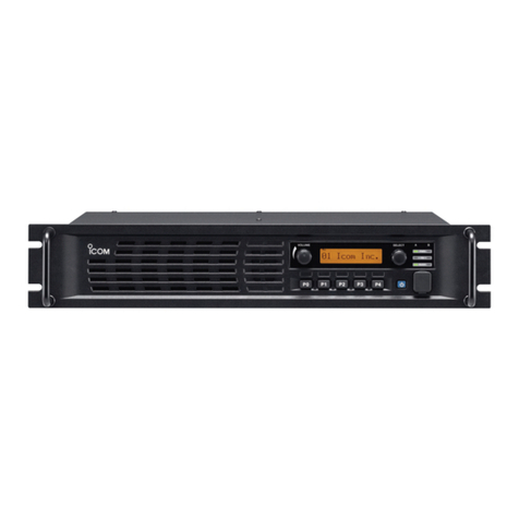
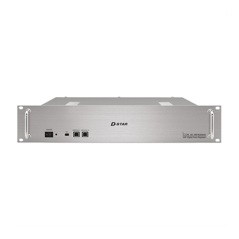
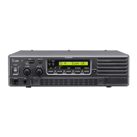
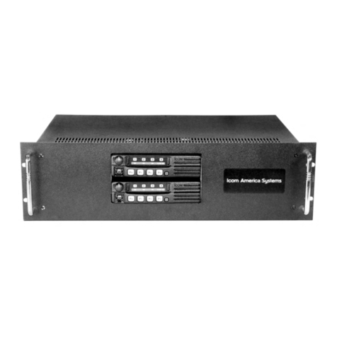
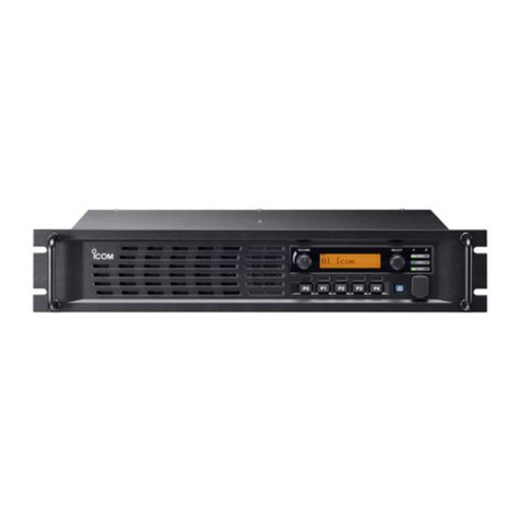
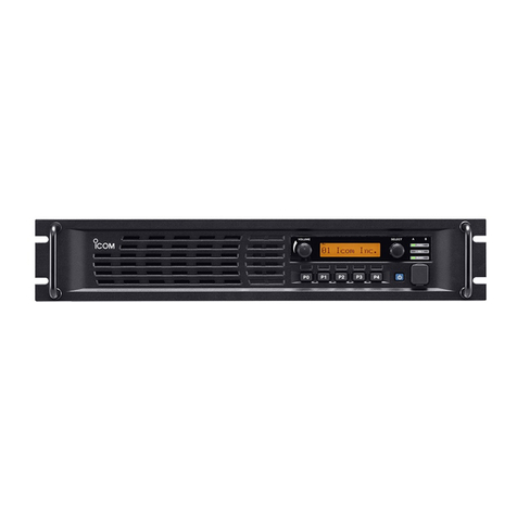
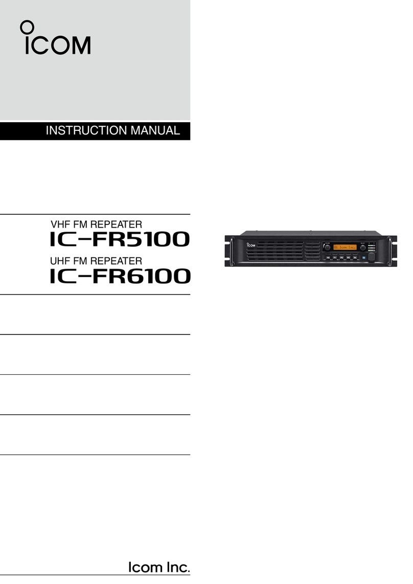
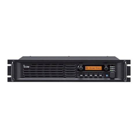
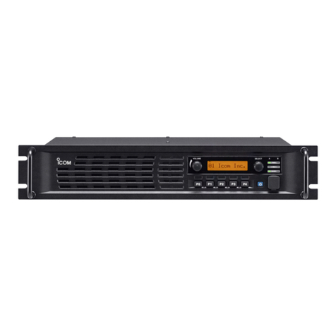
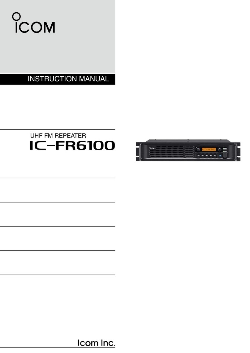
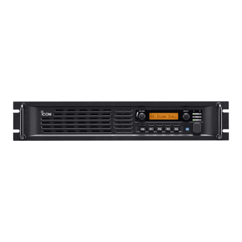
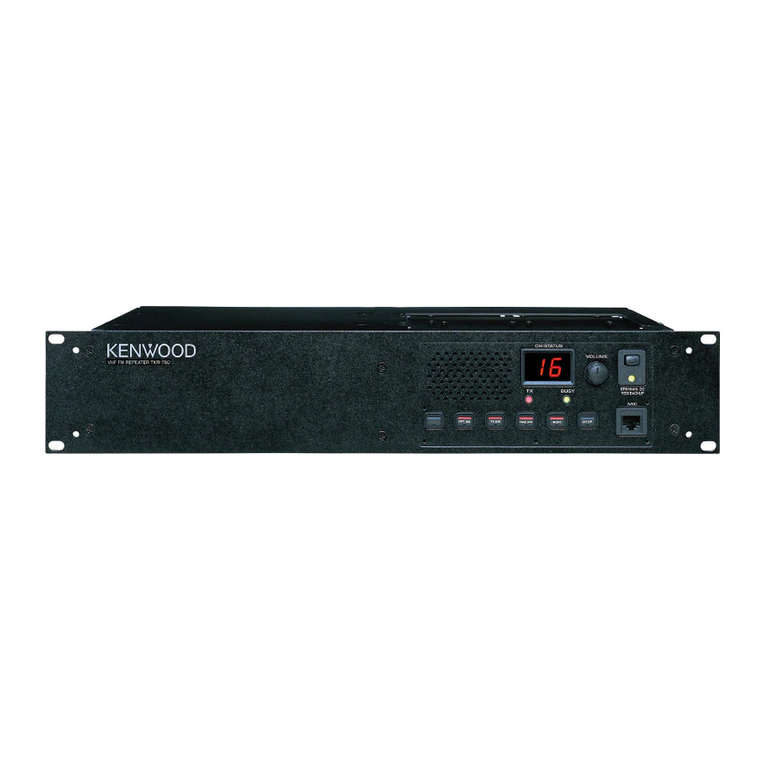
Icom IC-FR5000 Series User manual

ICIC--FR5000/FR6000 SeriesFR5000/FR6000 Series
Sales HandbookSales Handbook
Version 1.0
May 2008

FOR WORD and DISCLAIM R
The information in this document has been carefully checked, and is believed to be correct and accurate.
However, Icom assumes no responsibility for inaccuracies or mistakes. Furthermore, Icom reserves the right to
make changes to any of the products described in this handbook without notice or obligation. The systems and
applications described herein are for information and reference purposes only.
Handbook Revisions
Handbook RevisionsHandbook Revisions
Handbook Revisions
Icom reserves the right to make changes to the content of this handbook at any time without notice or
obligation.
IPR and opyrights
IPR and opyrightsIPR and opyrights
IPR and opyrights
The Icom products described in this handbook may include Icom Intellectual Property Rights (IPR) and/or
copyrighted Icom computer programs stored in radio memories or other media/devices. Such IPR and
copyrighted computer programs are protected by laws in Japan, the United States and other countries. Any
Icom IPR and/or copyrighted Icom computer programs contained in the Icom products described in this manual
Foreword
Disclaimer
This handbook is prepared to provide detailed information about the I -FR5000/I -FR6000 series VHF
and UHF FM Repeaters.
2
Icom IPR and/or copyrighted Icom computer programs contained in the Icom products described in this manual
may not be copied, reproduced, modified, reverse-engineered, or distributed in any way. Furthermore, the
purchase of Icom products shall not be deemed to grant any license either directly or by implication, except for
the normal non-exclusive license to use the product that is specified by law in the sale of a product.
Document opyrights
Document opyrightsDocument opyrights
Document opyrights
No duplication or distribution of this document or any portion thereof shall take place without the express
permission of Icom. Reproduction, distribution, or transmission for any purpose in any form or by any means,
electronic or mechanical, shall only be allowed with the express permission of Icom.
Trademarks
TrademarksTrademarks
Trademarks
Icom, Icom Inc. and the Icom logo are registered trademarks of Icom Incorporated (Japan) in the United States,
the United Kingdom, Germany, France, Spain, Russia and/or other countries.
Microsoft, Windows and Windows Vista are either registered trademarks or trademarks of Microsoft
orporation in the United States and/or other countries.
This product when used with certain options, utilizes vocoding technology that is the property of Digital Voice
Systems Inc. The AMBE+2™ voice coding Technology embodied in this product is protected by intellectual
property rights including patent rights, copyrights and trade secrets of Digital Voice Systems, Inc. This voice
coding Technology is licensed solely for use within this ommunications Equipment. The user of this Technology
is explicitly prohibited from attempting to extract, remove, decompile, reverse engineer, or disassemble the
Object ode, or in any other way convert the Object ode into a human-readable form. U.S. Patent Nos.
#5,870,405, #5,826,222, #5,754,974, #5,701,390, #5,715,365, #5,649,050, #5,630,011, #5,581,656,
#5,517,511, #5,491,772, #5,247,579, #5,226,084 and #5,195,166.
All other products or brands are registered trademarks or trademarks of their respective holders.
Regarding Application Examples
Regarding Application ExamplesRegarding Application Examples
Regarding Application Examples
All application examples shown in this handbook are for your reference only. Icom has not tested or carried out
performance checks for many of these examples, so does not guarantee they will work if tried. We suggest you
carry out testing before recommending to customers.
© 2008 Icom Inc.
Table of Contents
1 Introduction
1-1 ompanyProfile 4
2 Overview
2-1 ProductLineUp 5
2-2 ommonFeatures 6-7
2-3 6.25kHz FDMA Technology 8-12
2-4 Function and Specifications
2-4-1 VHFFMRepeaters 13
2-4-2 UHFFMRepeaters 14
3 Accessories
3-1 Optional Accessories 15
3-1-1 Installation and onnection 16-17
3-1-2 UR-FR5000/UR-FR6000 Installation 18-19
4 Operation and Function
4-1 Panel Description 20-21
4-1-1 Functions Programmable to Assignable Keys 22-23
4-1-2 DisplayAssign 24
4-1-3 onnector Description 25-26
4-2 loning Software S-FR5000
4-2-1 Basic Setup of loning Software 27-28
4
-
2
-
2
loning Items
29
Table of Contents
4
-
2
-
2
loning Items
29
4-3 Operation 30
4-4 MultipleTable 31
4-5 Remote ontrol Function 32-33
4-6 Scan 34-35
4-7 Voice Scrambling /Encryption 36-37
5 Applications
5-1 Digital-Analog Mixed System 38
5-1-1 Analog to Digital Migration Path 39
5-2 Digital-Analog ross System 40-42
5-3 Repeater Linking System
5-3-1 Repeater Linking System (1) 43
5-3-2 Repeater Linking System (2) 44
5-3-3 Repeater Linking System (3) 45
5-4 Phone Patch and Tone Remote 46
5-5 MPT1327 Trunking System 47-49
5-6 LTR™ Trunking System
5-6-1 Single Site LTR™ Trunking System 50
5-6-2 Digital Networked LTR™ or PassPort™ Trunking System 51
5-6-3 Analog Networked LTR™ or PassPort™ Trunking System 52
5-7 Solar Powered Repeater System 53-54
5-8 Wind-Solar Hybrid Powered Repeater System 55-56
5-9 Wind and Solar Power omponents 57
6 Maintenance 58
Appendix
A-1 Promotional Materials 59
A-2 Instruction Manual and Other Materials 60
3

1 Introduction
1-1 Company Profile
ompany Profile
ompany Profileompany Profile
ompany Profile
Icom, the wireless communication experts
Icom, the wireless communication expertsIcom, the wireless communication experts
Icom, the wireless communication experts
Icom Inc. is a company located in Osaka, Japan, and is a manufacturer of
wireless communication products. Since Icom’s establishment in 1954, we have
had a long record as a trusted manufacturer of land mobile radio, amateur radio,
marine radio, navigation products, aviation radio and communications receivers.
Quality & Reliability
Quality & ReliabilityQuality & Reliability
Quality & Reliability
Icom quality and Icom reliability
Icom quality and Icom reliabilityIcom quality and Icom reliability
Icom quality and Icom reliability
Over 50 years of engineering and production excellence is a part of every Icom
product. Using the latest equipment, Icom radios are tested to pass rigorous in-
house tests as well as environmental tests to the US Military standard 810
specifications. Icom Inc holds ISO9001:2000 certification.
Production
ProductionProduction
Production
Made in Japan quality
Made in Japan qualityMade in Japan quality
Made in Japan quality
Icom is a rare example of an electronics manufacturer that has not shifted
production to lower cost countries, but kept its production base 100% in Japan.
4
production to lower cost countries, but kept its production base 100% in Japan.
The Wakayama Icom plant has an advanced production system to produce small
volume/multi-model wireless communication products.
Icom brand
Icom brandIcom brand
Icom brand
Icom, world brand name
Icom, world brand nameIcom, world brand name
Icom, world brand name
Icom is today recognized as a reliable 2-way radio brand name around the world.
Our land mobile radios are used by many professional organizations all over the
world, like the United States Department of Defense and the U.S. Marine orps.
who chose Icom as the first Japanese company to supply radios to them.
Network
NetworkNetwork
Network
Icom's worldwide network
Icom's worldwide networkIcom's worldwide network
Icom's worldwide network
Icom’s products are sold in over 80 countries in the World. Icom has an
international sales and service network around the world, including sales
subsidiaries in the US, Australia, Germany, Spain and liaison offices in France
and hina. Icom is here to support and service our products and your
communication needs.

2 Overview
2-1 Product Line Up
VHF FM Repeater
VHF FM RepeaterVHF FM Repeater
VHF FM Repeater
UHF FM Repeater
UHF FM RepeaterUHF FM Repeater
UHF FM Repeater
5
Supplied Accessories Dimensions
W1 D Power able (OP -1784) ………… 1
MP1 3063 Handle ………………………………… 2
MP2 3063 H-Spacer ……………………………… 4
MP3 Setscrew ( ) (4x12 ZK3) ………………… 4
MP4 3063 Key Seal ……………………………… 1
88 (3 15/32)
483 (19 1/32)
Unit: mm (inch)
409 (16 3/32)
256 (10 1/4)
40 (1 9/16)

2-2 Common Features
“IDAS” 6.25KHZ DIGITAL APABLE REPEATERS
“IDAS” 6.25KHZ DIGITAL APABLE REPEATERS“IDAS” 6.25KHZ DIGITAL APABLE REPEATERS
“IDAS” 6.25KHZ DIGITAL APABLE REPEATERS
Digital/analog mixed mode operation
Digital/analog mixed mode operationDigital/analog mixed mode operation
Digital/analog mixed mode operation
The IDAS radio (including repeater) can receive both
analog mode and digital mode signals on a single
channel. You can partially introduce the IDAS digital
radios, while using the existing analog radios in a
system. The IDAS system allows you to scale migration
to narrow band digital at your own pace and need,
while running your existing analog system. A cost
efficient way to obtain the next generation in two way
radio technology.
Digital voice for clear audio
Digital voice for clear audioDigital voice for clear audio
Digital voice for clear audio
The IDAS radio uses the AMBE+2™ codec providing
crisp and clear communication and simultaneous data
communication.
Selective call, group call and talk group ID
Selective call, group call and talk group IDSelective call, group call and talk group ID
Selective call, group call and talk group ID
The IDAS system allows you to call individual or group
users. The talk group ID shows group ID, unit ID or
alias name on the display while receiving* a message.
* This function is similar to the analog mode PTT ID function,
however, the IDAS radio can keep sending ID information
during a voice transmission, so the receiving IDAS radio
can decode the ID even when breaking into a conversation.
(Late entry is possible)
Digital voice encryption
Digital voice encryptionDigital voice encryption
Digital voice encryption
IDAS DIGITAL FEATURES
IDAS DIGITAL FEATURESIDAS DIGITAL FEATURES
IDAS DIGITAL FEATURES
The I -FR5000/FR6000 series is the first Icom “IDAS” 6.25kHz digital capable repeater, in
addition to the I -F3160, F5060 series radios. The “IDAS” system increases existing 12.5kHz
channel capacity and offers easy migration from analog to digital.
6
Digital voice encryption
Digital voice encryptionDigital voice encryption
Digital voice encryption
The IDAS system provides secure communication
using a 15-bit key (about 32,000 keys) encryption.
RAN (Radio Access Number) for digital code squelch
RAN (Radio Access Number) for digital code squelchRAN (Radio Access Number) for digital code squelch
RAN (Radio Access Number) for digital code squelch
The RAN code provides a digital code for accessing the
IDAS repeater or digital code squelch function.
Double your channel capacity
Double your channel capacityDouble your channel capacity
Double your channel capacity
The IDAS system utilizes 6.25kHz narrow channel
spacing, which when in a 12.5kHz channel, you can
create two offset 6.25kHz channels. (i.e. doubling the
channel efficiency and capacity.) You can use these
channels, for example, in a one for voice and one for
data communication configuration.
Data communication
Data communicationData communication
Data communication
The IDAS system allows you 4800 bps* data
communication. You can send a data message or GPS
position data without an external data modem.
*Error correction, control data, etc, will reduce number of
bits available for actual data communication.
Other functions (Subscriber units only)
Other functions (Subscriber units only)Other functions (Subscriber units only)
Other functions (Subscriber units only)
• Status call/request • Radio check
• all alert • Remote radio stun/kill/revive
• Emergency call • all log
• Remote radio monitor
... Remotely turns on the PTT and transmits
anything the microphone hears for a
preprogrammed time period.
• Data call
... send and receive a data communication
• Simultaneous data call
... Send and receive data such as GPS position
information with a voice transmission

Common Features
REPEATER FEATURES
REPEATER FEATURESREPEATER FEATURES
REPEATER FEATURES
25W, 50W versions, high duty cycle operation
25W, 50W versions, high duty cycle operation25W, 50W versions, high duty cycle operation
25W, 50W versions, high duty cycle operation
Employing an effective cooling fan and high
performance power amplifier, the I -FR5000/FR6000
provides a stable 50W at 50% duty operation, and
25W output at 100% duty operation.
19
1919
19-
--
-inch rack mount, 2U height low profile design
inch rack mount, 2U height low profile designinch rack mount, 2U height low profile design
inch rack mount, 2U height low profile design
The I -FR5000 series has a rack mount bracket and
handles for installation in an industry standard 19-inch
rack. A 2U height configuration allows you to stack
multiple units in a rack.
Two RF modules in one unit
Two RF modules in one unitTwo RF modules in one unit
Two RF modules in one unit
The I -FR5000 series has an internal space for
installing another RF unit, the optional UR-FR5000
series. Two RF modules can be installed in the chassis
and reduces installation space, while the RF modules
can be programmed and operated independently.
5
55
5-
--
-Tone encoder/decoder
Tone encoder/decoderTone encoder/decoder
Tone encoder/decoder
When a preprogrammed 5-tone signal is received, the
I -FR5000 series starts and/or finishes repeater
operation (downlinking).
D
DD
D-
--
-SUB 25
SUB 25SUB 25
SUB 25-
--
-pin accessory connector
pin accessory connectorpin accessory connector
pin accessory connector
The I -FR5000 series has a D-SUB 25-pin accessory
connector for connecting LTR™/PassPort™ trunking*
controllers or other external devices. An operating
channel can be controlled by the input signal from the
D-SUB 25-pin connector. * Analog mode only.
Dot matrix, multi
Dot matrix, multiDot matrix, multi
Dot matrix, multi-
--
-function L D
function L Dfunction L D
function L D
A dot matrix L D is employed for the function display.
Up to 12 characters can be displayed. There are 5
programmable buttons on the front panel allowing you
to use the repeater as a base station.
32 memory channels
32 memory channels32 memory channels
32 memory channels
The I -FR5000 series has 32 memory channels. Each
memory channel stores a 12-character channel name,
digital/analog channel spacing, repeater/base
operation etc, as well as frequency setting.
Voice scrambler
Voice scramblerVoice scrambler
Voice scrambler
7
Multiple
MultipleMultiple
Multiple-
--
-table
tabletable
table
The I -FR5000 series detects multiple T SS, DT S
tone and digital RAN (Radio Access Number) codes on
a channel (up to 16 tones/codes on a table) and
downlinks (transmits) the received signal with a
specified tone. This function is useful for sharing a
channel with multiple groups and provides quiet stand-
by while using other groups.
Two RF units can be installed in the unit. (Left side is an option.)
Voice scrambler
Voice scramblerVoice scrambler
Voice scrambler
The I -FR5000 series has a built-in inversion type*
voice scrambler. When a more secure voice scrambler
system is required, the optional UT-109R/UT-110R* is
also available.
* The inversion type voice scrambler and UT-109R/UT-
110R voice scrambler is for analog mode only.
W ID transmission function*
W ID transmission function*W ID transmission function*
W ID transmission function*
Own W ID code or callsign can be sent at
preprogrammed intervals. The ID code can be used for
identifying the repeater. * Analog mode transmission
only.
Other features
Other featuresOther features
Other features
• Audio compander reduces background noise
• Wide frequency coverage (136–174MHz, 400–
470MHz and 450–520MHz)
• High frequency stability (±0.5ppm)
• PTT priority setting (Local mic, External PTT or
Repeater operation)
• Low voltage alert
• onvenient key assign stickers supplied

2-3 6.25 kHz FDMA Technology
Other methods were also considered, including A SB
and the proposed AP O Project 25 Phase II QPSK.
However, both required a more expensive linear
amplifier in the transmitter and neither is compatible
with existing analog FM hardware.
Instead, 4LFSK modulation was selected using FDMA
for transmission. This method has a number of
advantages:
•better communication range
•simpler design
•easy to maintain and service
•lower cost for business and industry customers
•compatible with existing FM radio hardware
Icom’s first radio with this technology is the
Background
BackgroundBackground
Background
As existing spectrum becomes increasingly scarce, the
demand for more options grows. The F essentially
created additional spectrum by adding hundreds of new
licenses with 6.25 kHz bandwidth. To take advantage of
this opportunity, Icom and Kenwood entered into a joint
agreement to develop 6.25 kHz technology. This
technology is a new digital communications protocol that
provides quality voice and data, and is designed as a
non-proprietary protocol. It accomplishes this by using
4LFSK (4-Level Frequency Shift Keying) and FDMA
(Frequency Division Multiple Access).
History
HistoryHistory
History
This technology was developed in response to an F
revision of the rules concerning transmitters in the
6.25kHz Digital mode ready*
6.25kHz Digital mode ready*6.25kHz Digital mode ready*
6.25kHz Digital mode ready*
The I -FR5000/FR6000 series are 6.25kHz digital mode ready*, the I -FR5000/FR6000 series
provides 6.25kHz digital narrow mode communication, and increases efficiency of channel
allocation and use of spectrum.
*For the USA version digital mode is turned ON, for the EXP version it is turned OFF when shipped from the
factory. Please ask your dealer for details.
8
Icom’s first radio with this technology is the
F3061/F4061. To enable backwards compatibility, the
radio is both analog and digital and also works in 25 kHz
and 12.5 kHz channel bandwidths (conventional and
LTR™ trunked operation in analog mode).
This new digital protocol, NXDN™ (Next Generation
Digital Narrowband) has been registered as a trademark
by Icom Inc. and Kenwood orporation. IDAS (Icom
Digital Advanced System) is the system based on this
NXDN™ technology.
The product range is steadily expanding , from handheld
transceivers to mobile transceivers to repeaters. All
products are/will be available for VHF and UHF bands.
revision of the rules concerning transmitters in the
150MHz to 174MHz and 421MHz to 512MHz range. To
receive F certification after January 1st 2005,
transmitters must have proved compliant as a multi-
mode device. This requirement could be achieved by
using 6.25 kHz channel bandwidth. In addition to the
F requirement, Europe and Japan are also moving
toward 6.25 kHz technologies. Because some in the
industry believed that this requirement could not be met
by 2005, the F suspended this requirement. (A new
deadline of January 1st 2011 has been set.)
Icom, however, went ahead to meet this requirement. It
was impossible to do using analog technology, so it
became necessary to develop a new digital protocol.

6.25 kHz FDMA Technology
Icom’s has implemented this technology in the
FR5000/6000 series. Backwards compatibility to
analog only radios enables a planned migration path to
“digital” with existing radios operating analog only and
new radios operating analog and digital.
General specifications:
General specifications:General specifications:
General specifications:
Access Method : FDMA
Transmission Rate : 4800 bps
Modulation
: 4
-
level FSK
S
SS
Spectrum o
pectrum opectrum o
pectrum onsiderations (VHF & UHF)*
nsiderations (VHF & UHF)*nsiderations (VHF & UHF)*
nsiderations (VHF & UHF)*
While most users are operating on 25 kHz channels,
they will have to migrate to 12.5 kHz bandwidth by
2013. Narrowband migration has not succeeded until
now, because of any incentive to do so.
9
Modulation
: 4
-
level FSK
Vocoder : AMBE+2™
odec Rate : 3600 (Voice 2,450 + Error
orrection 1,150 bps)
Modulation with 4LFSK uses a symbol mapping scheme.
When the radio receives a binary number, that number
is mapped to a symbol, which is interpreted as a
1050Hz frequency deviation.
The deviation is detected, filtered and “unmapped” as a
binary signal for transmission.
Range
RangeRange
Range
Audio quality over distance is also greatly improved with
Icom’s 6.25 kHz technology. Instead of the early
degradation of audio that you see in an analog signal,
the 6.25 kHz digital audio quality remains higher over a
comparable distance.
A channel is defined by the deviation either side of the
center line frequency. Migrating from a 25 kHz channel
to a 12.5 kHz channel on the same centerline frequency
is a 1-for-1 move. There is no increase in the capacity to
load radio users.
There are 500 new 6.25 kHz frequencies (VHF and UHF)
available now. Most are unused because no 6.25 kHz
radios were available. With Icom’s FDMA technology,
frequency coordinators have total flexibility to either
assign a 6.25 kHz channel within an existing 25 kHz or
12.5 kHz channel or as a stand-alone frequency some
where else on the band. A frequency coordinator will
coordinate channels for minimum adjacent channel
interference.
Most users on 25 kHz
Must move to 12.5
kHz by 2013
500 unused 6.25 kHz
channels, no radios
* Some of the content above applies to the U.S.A. only.

6.25 kHz FDMA Technology
6.25 kHz channel
6.25 kHz channel6.25 kHz channel
6.25 kHz channel 12.5 kHz channel
12.5 kHz channel12.5 kHz channel
12.5 kHz channel
Because the emission mask is tight, 6.25 kHz channels can be used next to each other without causing
interference. The bandwidth measurements below show the 6.25kHz FDMA signal meets the F designated
emission mask requirements.
The figure on the left is the emission mask for a 6.25 kHz channel. The Icom 6.25kHz FDMA signal clearly
operates within the mask. Accordingly, the F certified the F3061/4061 as the first ever 6.25 kHz radio.
The figure on the right is the emission mask for a 12.5 kHz channel. With a 12.5 kHz channel, you can create
two offset 6.25 kHz channels.
10
6.25kHz FDMA12.5kHz Analog FM
NOTE:
NOTE:NOTE:
NOTE: The double capacity example shown above may not apply to some countries depending on local regulations.
6.25 kHz FDMA makes twice the number of channels available within the same spectrum as shown below. This
is a real solution to meet expanding demand for spectrum every year.

6.25 kHz FDMA Technology
With a 12.5 kHz channel, you can create two offset 6.25
kHz channels.
2
22
2
-
--
-
for
forfor
for
-
--
-
1
11
1
Split a 25 kHz or 12.5 kHz hannel
Split a 25 kHz or 12.5 kHz hannelSplit a 25 kHz or 12.5 kHz hannel
Split a 25 kHz or 12.5 kHz hannel
Both 2-for-1 and 4-for-1 efficiencies may be realized by
splitting existing channels. Using 6.25 kHz channels
offset from the center of a 25 kHz channel, it is possible
to fit four 6.25 kHz channels into the 25 kHz bandwidth.
To do this, a waiver from the F is required*. Using this
scheme, the four frequencies are now offset 3.125 kHz
from the original 25 kHz channel center frequency.
4
44
4-
--
-for
forfor
for-
--
-1
11
1
U
UU
UHF onsiderations*
HF onsiderations*HF onsiderations*
HF onsiderations*
A number of frequency allocation options for 6.25 kHz
are available in UHF.
Note:
Note: Note:
Note: the following options illustrate potential spectrum
opportunities with 6.25 kH technology. Actual
opportunities may vary by locale and other conditions.
Please check with your frequency coordinator for
opportunities available in your location.
Obtain New 6.25 kHz Frequencies
Obtain New 6.25 kHz FrequenciesObtain New 6.25 kHz Frequencies
Obtain New 6.25 kHz Frequencies
This may be the best option for a new radio user in a
location where no channels are available. Each 6.25 kHz
frequency is unique. Existing 25 kHz or 12.5 kHz
channels do not have to be “split.” This gives the
greatest flexibility to the frequency coordinator.
New New
11
2
22
2
-
--
-
for
forfor
for
-
--
-
1
11
1
Expand an Existing System
Expand an Existing SystemExpand an Existing System
Expand an Existing System
Spectrum holders can apply for some new additional
6.25 kHz channels and combine them with their
current 25 or 12.5 kHz channels. New frequencies
could occupy the existing 25 kHz or 12.5 kHz
bandwidth. Additional stand-alone 6.25 kHz channels
could also be used.
hannel 1
hannel 2 hannel 3
Hedge Strategy
Hedge StrategyHedge Strategy
Hedge Strategy
If you start at the center frequency, you can license 5
each 6.25 kHz frequencies underlying a 25 kHz channel.
The 2 outer frequencies are out of the 25 kHz channel
width. This provides license holders with a “hedge”
against losing that spectrum in 2013 when they will be
forced to 12.5 kHz.
* Some of the content above applies to the U.S.A. only.
*Note: No waiver needed if a 12.5 kHz channel is
exclusive (FB8), under part [90.173(j)]

6.25 kHz FDMA Technology
Future Applications for 6.25kHz Technology
Future Applications for 6.25kHz TechnologyFuture Applications for 6.25kHz Technology
Future Applications for 6.25kHz Technology
This new digital land mobile technology can be a platform for future integration of IT/IP/VOIP technologies. To this
end, there are some initiatives between a number of manufacturers to promote 6.25kHz technology more widely.
VHF onsiderations*
VHF onsiderations*VHF onsiderations*
VHF onsiderations*
The VHF narrowband plan is 7.5 kHz channels, which
has eliminated the geographical separation
requirement. Tests have proven the Icom 6.25 kHz
signal can be used within a 7.5 kHz channel with no
interference to the adjacent channel.
Split a 25 kHz or 12.5 kHz hannel
Split a 25 kHz or 12.5 kHz hannelSplit a 25 kHz or 12.5 kHz hannel
Split a 25 kHz or 12.5 kHz hannel
This is similar to the UHF application. With a 12.5 or
25 kHz channel, you can create two or four offset 6.25
kHz channels. This may require a waiver from the F .
One 25 kHz hannel to Three 6.25 kHz hannels
One 25 kHz hannel to Three 6.25 kHz hannelsOne 25 kHz hannel to Three 6.25 kHz hannels
One 25 kHz hannel to Three 6.25 kHz hannels
A single 25 kHz channel can be converted to three
6.25 kHz channels, each operating within a 7.5 kHz
channel.
* Some of the content above applies to the U.S.A. only.
VHF offers even more opportunities due to its original
30 kHz channel width plan. When the F moved to
25 kHz and then 12.5 kHz an overlap was created
requiring geographical separation between two
contiguous channels. For example, 3 contiguous could
not be used at the same location.
12
This new digital land mobile technology can be a platform for future integration of IT/IP/VOIP technologies. To this
end, there are some initiatives between a number of manufacturers to promote 6.25kHz technology more widely.
An example is the formation of the dPMR MoU in Europe, and the F in the U.S.A. has recently proposed that
system owners consider switching to 6.25kHz technology where possible. Japan and hina are also considering
6.25kHz for future digital radio standards.
The above is system is an image only.

2-4 Function and Specifications
2-4-1 VHF FM Repeaters
Model No. I -FR5000 I -FR5000
Version #01 #03
Destinations USA-01 EXP-01
Type Approval F Local T/A
Function omparison
T SS ✔ ✔
DT S ✔ ✔
2-Tone
5-Tone ✔ ✔
DTMF Autodial ✔ ✔
DTMF Decoder ✔ ✔
BIIS 1200
MD 1200
6.25kHz digital ✔Note *1
MPT 1327
LTR™ Trunking
PassPort™
Intrinsically Safe
SPE IFI ATIONS
Frequency Range (MHz) 136 ~ 174 136~ 174
Number of channels 32 h
hannel Spacing (kHz)
6.25/12.5/25,
7.5/15/30
6.25*
1
/12.5/25
13
GENERAL
hannel Spacing (kHz)
6.25/12.5/25,
7.5/15/30
6.25*
/12.5/25
PLL channel step (Unit: kHz) 2.5, 3.125
Power supply requirement 13.6V D (Negative ground)
urrent drain
Tx 50W 15A
Rx Stand-by 500mA (typ.), 400mA(FAN,L D backlight off)
Max. audio 1900mA (typ.)
Dimensions (W×H×D)
(projections not included)
483×88×260mm
19132×31532×1014in
Weight (approx.) 5.6kg; 12.3lb
TX
RF output power (High) 50W (25W at 100% duty cycle)
Spurious emissions 80dB (typ.)
Adjacent channel power Wide 76 dB (typ.), Narrow 69dB (typ.), Digital 65 dB (typ.)
RX
Sensitivity Wide/Narrow 0.3µV (typ.) at 12dB SINAD
Digital 0.25µV (typ.) at 5% BER
Adjacent channel selectivity Wide 80 dB (typ.), Narrow 56 dB (typ.), Digital 63 dB (typ.)
Spurious response 90dB (typ)
Intermodulation rejection 78dB (typ)
Audio output power 4W (typ.) at 5% distortion with a 4 load
Specifications are measured in accordance with TIA-603-B (for Wide and Narrow) or EN 300 166 (Digital) for I -
FR5000.
All stated specifications are subject to change without notice or obligation.
Note *1: 6.25kHz digital capability can be turned ON if required.

2-4-2 UHF FM Repeaters
Model No. I -FR6000 I -FR6000 I -FR6000 I -FR6000
Version #01 #11 #03 #13
Destinations USA-01 USA-02 EXP-01 EXP-02
Type Approval F F Local T/A Local T/A
Function omparison
T SS ✔ ✔ ✔ ✔
DT S ✔ ✔ ✔ ✔
2-Tone
5-Tone ✔ ✔ ✔ ✔
DTMF Autodial ✔ ✔ ✔ ✔
DTMF Decoder ✔ ✔ ✔ ✔
BIIS 1200
MD 1200
6.25kHz digital ✔ ✔ Note *1Note *1
MPT 1327
LTR™ Trunking
PassPort™
Intrinsically Safe
SPE IFI ATIONS
Frequency Range (MHz) 400 ~ 470 450 ~ 520 400 ~ 470 450 ~ 520
Number of channels 32 h
hannel Spacing (kHz)
6.25/12.5/25
6.25*
1
/12.5/25
14
GENERAL
hannel Spacing (kHz)
6.25/12.5/25
6.25*
/12.5/25
PLL channel step (Unit: kHz) 2.5, 3.125
Power supply requirement 13.6V D (Negative ground)
urrent
drain
Tx 50W 15A
Rx Stand-by 500mA (typ.), 400mA(FAN,L D backlight off)
Max. audio 1900mA (typ.)
Dimensions (W×H×D)
(projections not included)
483×88×260mm
19132×31532×1014in
Weight (approx.) 5.6kg; 12.3lb
TX
RF output power (High) 50W (25W at 100% duty cycle)
Spurious emissions 80dB (typ.)
Adjacent channel power Wide 73 dB (typ.), Narrow 67dB (typ.), Digital 65 dB (typ.)
RX
Sensitivity Wide/Narrow 0.3µV (typ.) at 12dB SINAD, Digital 0.25µV (typ.) at 5% BER
Adjacent channel selectivity Wide 78 dB (typ.), Narrow 56 dB (typ.), Digital 63 dB (typ.)
Spurious response 90dB (typ.)
Intermodulation rejection 78dB (typ.)
Audio output power 4W (typ.) at 5% distortion with a 4 load
Specifications are measured in accordance with TIA-603-B (for Wide and Narrow) or EN 300 166 (Digital) for I -
FR6000.
All stated specifications are subject to change without notice or obligation.
Note *1: 6.25kHz digital capability can be turned ON if required.

3-1 Optional Accessories
HAND MI ROPHONES
HAND MI ROPHONESHAND MI ROPHONES
HAND MI ROPHONES DESKTOP MI ROPHONE
DESKTOP MI ROPHONEDESKTOP MI ROPHONE
DESKTOP MI ROPHONE
* Some optional accessories are not available in some countries.
INTERNAL UNITS
INTERNAL UNITSINTERNAL UNITS
INTERNAL UNITS
SP
SPSP
SP-
--
-22
22 22
22 : ompact and easy-
to-install external speaker.
Input impedance : 4 Ω
Max. input power : 5 W
SP
SPSP
SP-
--
-10
10 10
10 : Mid sized
external speaker.
Input impedance : 4 Ω
Max. input power : 5 W
SP
SPSP
SP-
--
-5
5 5
5 : Large external
speaker.
Input impedance : 4 Ω
Max. input power : 5 W
EXTERNAL SPEAKERS
EXTERNAL SPEAKERSEXTERNAL SPEAKERS
EXTERNAL SPEAKERS
15
Swivel type.
MB-86 and MB-93
swivel joints supplied
HM
HMHM
HM-
--
-152
152 152
152 : Regular hand
microphone.
SM
SMSM
SM-
--
-25 :
25 : 25 :
25 : onvenient for
dispatching, equipped with
monitor switch.
UT
UTUT
UT-
--
-110R :
110R : 110R :
110R : Voice
scrambler unit
Rolling type (max. 1020
codes).
UT
UTUT
UT-
--
-109R :
109R : 109R :
109R : Voice
scrambler unit
Non-rolling type (max.
32 codes).
LONING ABLE
LONING ABLELONING ABLE
LONING ABLE LONING SOFTWARE
LONING SOFTWARELONING SOFTWARE
LONING SOFTWARE
• UR
• UR• UR
• UR-
--
-FR6000
FR6000 FR6000
FR6000 UHF
HANNEL MODULE
400–470MHz, 450–
520MHz, 50W
• UR
• UR• UR
• UR-
--
-FR5000
FR5000 FR5000
FR5000 VHF
HANNEL MODULE
136–174MHz, 50W
HANNEL EXTENSION
HANNEL EXTENSIONHANNEL EXTENSION
HANNEL EXTENSION
OP
OPOP
OP -
--
-1122U
1122U 1122U
1122U : LONING ABLE (USB
type) onsist of;
•OP -1122U 250mm
•OP -1637 (USB cable) 1500mm
•D (USB driver software)
S
SS
S-
--
-FR5000
FR5000 FR5000
FR5000 : For programming
versions of the I -FR5000/FR6000
series VHF/UHF FM REPEATERS.

3-1-1 Installation and onnections
Installation and onnectionsInstallation and onnections
Installation and onnections
Front panel connections
Front panel connectionsFront panel connections
Front panel connections
Unpacking
UnpackingUnpacking
Unpacking
After unpacking, immediately report any damage to the
delivering carrier or dealer. Keep the shipping cartons.
For a description and a diagram of accessory
equipment included with the I -FR5000/FR6000
series, see ‘Supplied accessories’ on page 5 of this
handbook.
Selecting a location
Selecting a locationSelecting a location
Selecting a location
Select a location for the repeater that allows adequate
air circulation, free from extreme heat, cold, or
vibrations, and away from TV sets, TV antenna
elements, radios and other electromagnetic sources.
Antenna
AntennaAntenna
Antenna connection
connectionconnection
connection
For radio communications, the antenna is of critical
importance, along with output power and sensitivity.
Select antenna(s), such as a well-matched 50 Ω
antenna, and feedline. 1.5:1 or better of Voltage
Standing Wave Ratio (VSWR) is recommended for the
desired band. Of course, the transmission line should
be a coaxial cable.
▒ AUTION:
AUTION: AUTION:
AUTION: Protect repeater from lightning by using
▒ a lightning arrestor.
16
▒ a lightning arrestor.
▒ NOTE:
NOTE: NOTE:
NOTE: There are many publications covering
▒ proper antennas and their installation. heck with
▒ your local dealer for more information and
▒ recommendations

Installation and Connections
Rear panel connections
Rear panel connectionsRear panel connections
Rear panel connections
17
Power supply connection
Power supply connectionPower supply connection
Power supply connection
Make sure the repeater’s power is turned OFF when
connecting a D power cable.
▒ AUTION:
AUTION: AUTION:
AUTION: Voltages greater than 16 V D will damage
▒ the repeater. heck the source voltage before
▒ connecting the power cable.
Mounting the repeater
Mounting the repeaterMounting the repeater
Mounting the repeater
Using the supplied handle
Using the supplied handleUsing the supplied handle
Using the supplied handle
The supplied handles are available for mounting the
repeater into a 19 inch rack. The handles can be
installed to the repeater’s front panel.
1Attach the supplied handles to both sides of the
repeater’s front panel with the spacers, then tighten
the screws as below.
2The completed installation should look like
as below.

3-1-2 UR-FR5000/UR-FR6000 Installation
UR
URUR
UR-
--
-FR5000/UR
FR5000/URFR5000/UR
FR5000/UR-
--
-FR6000 HANNEL EXTENSION
FR6000 HANNEL EXTENSION FR6000 HANNEL EXTENSION
FR6000 HANNEL EXTENSION
MODULES
MODULES MODULES
MODULES
SUPPLIED A ESSORIES
SUPPLIED A ESSORIES SUPPLIED A ESSORIES
SUPPLIED A ESSORIES
1D power cable ....................................................1
2ontrol cable .........................................................1
3Angles ...................................................................2
4Screws (M4×8 mm) ............................................. 4
5Set screws (M3×6 mm) ....................................... 4
6Tapping screws (M3×8 mm) ...............................2
1 mm = 1/32 inch
OPENING ASE
OPENING ASEOPENING ASE
OPENING ASE
3Disconnect the control cable from the channel
module (original), then remove the front panel.
4Remove 6 screws from the front panel, then remove
the shielding plate and rubber seal.
hannel module(original)
Front panel
Shielding plate
Rubber seal
18
OPENING ASE
OPENING ASEOPENING ASE
OPENING ASE
1Remove 7 screws from top and 2 screws each from
both sides of the repeater, then slide off the top cover to
the direction of the arrow as illustrated below.
2Remove 3 screws from bottom and 2 screws each
from both sides of the repeater.
Rubber seal

UR-FR5000/UR-FR6000 Installation
INSTALLATION
INSTALLATIONINSTALLATION
INSTALLATION
• Install the UR
• Install the UR• Install the UR
• Install the UR-
--
-FR5000 or UR
FR5000 or URFR5000 or UR
FR5000 or UR-
--
-FR6000(channel
FR6000(channel FR6000(channel
FR6000(channel
extension module)
extension module)extension module)
extension module)
1Attach the supplied angles to both sides of the
channel extension module, and tighten the 2 supplied
screws (M4×8) on each side.
2Install the channel extension module using the
supplied screws (Tapping screws: M3×8, Set screws:
M3×6) as shown below.
Set screws
Tapping
screws
hannel extension
module
hannel module
(original)
ASSEMBLE THE UNIT
ASSEMBLE THE UNITASSEMBLE THE UNIT
ASSEMBLE THE UNIT
1Replace the rubber seal and shielding plate of the
front panel, then tighten the 6 screws.
• Make sure the rubber seal is properly seated in the
groove of the chassis.
• Be sure to match the correct positions of the holes
of the shielding plate and projections of the front
panel’s chassis.
2onnect the control cables to the channel modules.
hannel extension module
hannel module
(original)
Projections
Rubber seal
Holes
19
• onnect the control cable
• onnect the control cable• onnect the control cable
• onnect the control cable
1onnect the supplied control cable to J502 on the
front board as shown below.
2ut the rubber caps of the control cables, then
insert the rubber caps to the front panel’s chassis
as shown below. 3Return the front panel, top cover and screws to their
original positions.
(original)
Shorter cable
(lower side)
Longer cable
(upper side)

4 Operation and Function
4-1 Panel Description
Note: Operation of the functions described below may depend on repeater programming.
❶INTERNAL SPEAKER
INTERNAL SPEAKERINTERNAL SPEAKER
INTERNAL SPEAKER
Monitors received signals.
❷VOLUME ONTROL [VOLUME]
VOLUME ONTROL [VOLUME] VOLUME ONTROL [VOLUME]
VOLUME ONTROL [VOLUME]
Adjusts the audio output level.
❸SELE TOR DIAL [SELE T]
SELE TOR DIAL [SELE T]SELE TOR DIAL [SELE T]
SELE TOR DIAL [SELE T]
Rotate to adjust the squelch threshold level, select
the operating channel. (Depending on the pre
-
❼MI ROPHONE/SPEAKER ONNE TOR [MI /SP]
MI ROPHONE/SPEAKER ONNE TOR [MI /SP]MI ROPHONE/SPEAKER ONNE TOR [MI /SP]
MI ROPHONE/SPEAKER ONNE TOR [MI /SP]
This 8-pin modular jack accepts the optional
microphone.
▒ KEEP
KEEP KEEP
KEEP the [MI ]
[MI ] [MI ]
[MI ] connector cover attached to the
▒ repeater when the optional microphones is not
▒ used.
_______________________________________________________________
20
the operating channel. (Depending on the pre
-
programmed condition.)
❹POWER INDI ATOR [POWER]
POWER INDI ATOR [POWER]POWER INDI ATOR [POWER]
POWER INDI ATOR [POWER]
➥Lights green at ‘A’ module’s indicator while the
repeater power is turned ON.
When a channel extension module is installed:
When a channel extension module is installed:When a channel extension module is installed:
When a channel extension module is installed:
➥Light green at the selected module indicator (‘A’
or ‘B’) while the repeater power is turned ON.
➥Lights orange at the un-selected module indicator
(‘A’ or ‘B’) while the repeater power is turned ON.
❺TRANSMIT INDI ATOR [TX]
TRANSMIT INDI ATOR [TX]TRANSMIT INDI ATOR [TX]
TRANSMIT INDI ATOR [TX]
Lights red while transmitting.
❻BUSY INDI ATOR [BUSY]
BUSY INDI ATOR [BUSY]BUSY INDI ATOR [BUSY]
BUSY INDI ATOR [BUSY]
Lights green while receiving a signal or when the
noise squelch is open.
▒ About [PWR], [TX] and [BUSY] indicator:
About [PWR], [TX] and [BUSY] indicator:About [PWR], [TX] and [BUSY] indicator:
About [PWR], [TX] and [BUSY] indicator:
▒ ‘A’ and ‘B’ modules indicators are available for
▒ these indications. ‘A’ module’s indicator corresponds
▒ to the original module, and ‘B’ module’s indicator
▒ corresponds to an extended module.
_______________________________________________________________
➀+8 V D output (Max. 15 mA)
➁I/O port for P programming
➂N
➃M PTT (Input port for TX control)
➄Microphone ground
➅Microphone input
➆Ground
➇M MONI (Input port for monitor control)
______________________________________________________________________________________________________________________________________________________________
❽POWER SWIT H [POWER]
POWER SWIT H [POWER]POWER SWIT H [POWER]
POWER SWIT H [POWER]
➥Push to turn the repeater power ON.
➥Push and hold for 3 sec. to turn the repeater
power OFF.
When a channel extension module is installed:
When a channel extension module is installed:When a channel extension module is installed:
When a channel extension module is installed:
➥While the repeater power is turned ON, push to
select the desired module to operate the repeater
as the base station.
•The power indicator of the selected module unit
lights green.
❾DEALER
DEALERDEALER
DEALER-
--
-PROGRAMMABLE KEYS
PROGRAMMABLE KEYSPROGRAMMABLE KEYS
PROGRAMMABLE KEYS
Desired functions can be programmed independently
by your dealer.
Ask your dealer for details.
•Because these keys are programmable, the
functions of these keys are unique to each unit.
This manual suits for next models
2
Table of contents
Other Icom Repeater manuals

Icom
Icom IC-FR4000 Series User manual

Icom
Icom IC-RP1210 User manual

Icom
Icom F6000 User manual

Icom
Icom CY-5300 User manual

Icom
Icom iFR5000 User manual

Icom
Icom iC-FR5000 User manual

Icom
Icom IC-RP2210 Service manual

Icom
Icom UR-FR5000 User manual

Icom
Icom IC-RP1520 User manual

Icom
Icom FR9020 11 User manual

Icom
Icom IC-RP2210 Service manual

Icom
Icom ID-RP1 User manual

Icom
Icom IC-UR8050 User manual

Icom
Icom IC-FR5300 User manual

Icom
Icom iC-FR5000 User manual

Icom
Icom UHF FM Repeater iFR6100 User manual

Icom
Icom IC-RP1520 User manual

Icom
Icom iC-FR5000 User manual

Icom
Icom IC-RP1510 User manual

Icom
Icom IC-FR3000 Series User manual