D1033 - SIL 2 Switch / Proximity Detector Repeater Transistor OutputG.M. International ISM0043-11 7
D1033 series are isolated Intrinsically Safe Associated Apparatus installed into standard EN50022 T35 DIN Rail located in Safe Area/Non Hazardous Locations or Zone 2, Group IIC,
Temperature Classification T4, Class I, Division 2, Groups A, B, C, D, Temperature Code T4 and Class I, Zone 2, Group IIC, IIB, IIA Temperature Code T4 Hazardous Area/Hazardous
Locations (according to EN/IEC60079-15, FM Class No. 3611, CSA-C22.2 No. 213-M1987, CSA-E60079-15) within the specified operating temperature limits Tamb -20 to +60 °C,
and connected to equipment with a maximum limit for AC power supply Um of 250 Vrms.
Non-incendive field wiring is not recognized by the Canadian Electrical Code, installation is permitted in the US only.
For installation of the unit in a Class I, Division 2 or Class I, Zone 2 location, the wiring between the control equipment and the D1033 associated apparatus shall be accomplished
via conduit connections or another acceptable Division 2, Zone 2 wiring method according to the NEC and the CEC.
Not to be connected to control equipment that uses or generates more than 250 Vrms or Vdc with respect to earth ground.
D1033 series must be installed, operated and maintained only by qualified personnel, in accordance to the relevant national/international installation standards
(e.g. IEC/EN60079-14 Electrical apparatus for explosive gas atmospheres - Part 14: Electrical installations in hazardous areas (other than mines), BS 5345 Pt4, VDE 165,
ANSI/ISA RP12.06.01 Installation of Intrinsically Safe System for Hazardous (Classified) Locations, National Electrical Code NEC ANSI/NFPA 70 Section 504 and 505,
Canadian Electrical Code CEC) following the established installation rules, particular care shall be given to segregation and clear identification of I.S. conductors from non I.S. ones.
De-energize power source (turn off power supply voltage) before plug or unplug the terminal blocks when installed in Hazardous Area/Hazardous Locations or
unless area is known to be nonhazardous.
Warning: substitution of components may impair Intrinsic Safety and suitability for Division 2, Zone 2.
Explosion Hazard: to prevent ignition of flammable or combustible atmospheres, disconnect power before servicing or unless area is known to be nonhazardous.
Failure to properly installation or use of the equipment may risk to damage the unit or severe personal injury.
The unit cannot be repaired by the end user and must be returned to the manufacturer or his authorized representative. Any unauthorized modification must be avoided.
Warning
Operation
D1033 accepts as an input from Hazardous Area/Hazardous Locations a proximity sensor or voltage free electrical contact and repeats their status to Safe Area/Non Hazardous
Locations by optoisolated open collector transistor. Presence of supply power and status of output (energized or de-energized), as well as integrity or fault condition of sensor and
connecting line are displayed by signaling LEDs (green for power, yellow for status and red for fault condition). D1033Q (quad channel type) has four independent isolated input channels
and actuates the corresponding output transistor; two actuation modes can be independently DIP switch configured for each input channel:
Normally open input / Normally close transistor or Normally close input / Normally close transistor
Contact or proximity sensor and its connection line short or open circuit fault detection is also DIP switch configurable. Fault detection can be enabled (in case of fault de-energizes the
corresponding output channel transistor (open) and turns ON the fault LED) or be disabled (in case of fault the corresponding output channel transistor repeats the input line open or
close status as configured). D1033D (dual channel type) has two isolated input channel and four output transistors; the unit has two DIP switch configurable operating modes:
A) Input channel actuates in parallel output transistors (providing a DPST type of output). Transistors actuation can be independently configured for each output in two modes:
Normally open input / Normally close transistor or Normally close input / Normally close transistor
B) Input channel actuates output transistor (A) configurable in two modes as above. Output transistor B operates as fault output (in case of input fault, transistor B actuates and the
fault LED turns on while transistor A repeats the input line as configured). Actuation can be configured in two modes:
No input fault / Close transistor (it de-energizes in case of fault) or No input fault / Open transistor (it energizes in case of fault).
Note: use of voltage free electrical contacts with fault detection enabled requires, near the switch at the end of the line, a 1 Kseries connected resistor and a 10 Kparallel connected
resistor in order to allow the fault detection circuit to distinguish between a condition of contact close/ open and a line open/short circuit fault.
D1033 Associated Apparatus
FM Approved
under Entity Concept
and non-incendive field wiring
Unclassified Locations or
Hazardous (Classified) Locations
Class I, Division 2, Groups A, B, C, D, T-Code T4
Class I, Zone 2, Group IIC, IIB, IIA, T-Code T4
FM Approved under Entity Concept,
or third party approval
Hazardous (Classified) Locations
Class I, Division 1, Groups A, B, C, D
Class II, Division 1, Groups E, F, G
Class III, Division 1
Class I, Zone 0, Group IIC, IIB, IIA
Intrinsically
Safe Equipment
Must not use or generate
more than 250 Vrms or Vdc
Control
Equipment
Unclassified Locations
Hazardous (Classified) Locations
Class I, Division 2, Groups A, B, C, D
Class II, Division 2, Groups E, F, G
Class III, Division 2
Class I, Zone 2, Group IIC, IIB, IIA
FM Approved under non-incendive field
wiring (permitted only for US installations),
or third party approval
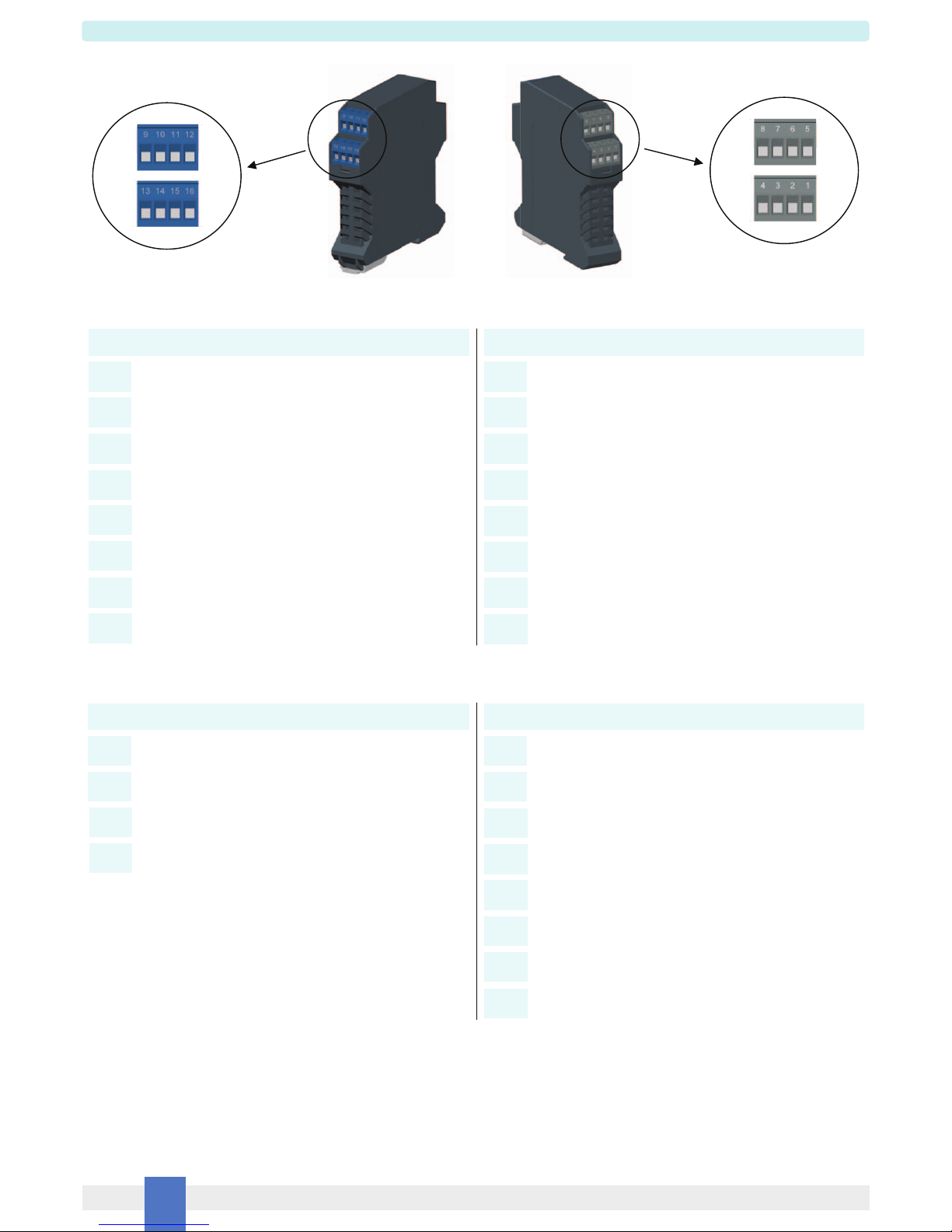
13
14
1
2
+
-
-
+
Power Supply
3
4
16
15
-
+
Intrinsically
Safe Equipment
Unclassified Locations or
Hazardous (Classified) Locations
Class I, Division 2, Groups A, B, C, D, T-Code T4
Class I, Zone 2, Group IIC, IIB, IIA, T-Code T4
Unclassified Locations
Must not use or generate
more than 250 Vrms or Vdc
6
5Control
Equipment
Control
Equipment
Control
Equipment
2
6
8
7
Intrinsically
Safe Equipment -
+
10
9
Intrinsically
Safe Equipment
+
-
11
12
+
-Power Supply
Control
Equipment
Control
Equipment
Control
Equipment
Control
Equipment
14
9
11
12
10
16
15
13
4
3
2
7
8
6
2
6
5
1+
-
+
+
-
-
-
+
Non-incendive
Equipment
Non-incendive
Equipment
Non-incendive
Equipment
Non-incendive
Equipment
D1033 Associated Apparatus
FM Approved
under Entity Concept
and non-incendive field wiring