manuals.online logo
Brands
  1. Home
  2. •
  3. Brands
  4. •
  5. Honeywell
  6. •
  7. Repeater
  8. •
  9. Honeywell SiXREPEATER User manual

Honeywell SiXREPEATER User manual

SiXREPEATER Wireless Repeater / Wireless Repeater
Quick Installation Guide
Guide d'installation rapide
The Honeywell SiXREPEATER is an RF receiver and a transmitter and is intended to
extend the range of Honeywell’s SiX series devices by 200 feet (nominal). The
SiXREPEATER receives alarm, status, and control messages from SiX series
devices, and forwards these messages to control panel. The control then responds
accordingly (arm/disarm the system, initiate an alarm, etc.
FEATURES
•Transmits its own status, including tamper, AC loss, and RF Jam.
•Status sent when change occurs or during the one hour supervisory check in.
•Provides a 24-hour backup rechargeable battery.
•Features a Spatial Diversity system that virtually eliminates the possibility of
"Nulls" and "Dead Spots" within the coverage area.
•Front and wall tampers
GENERAL GUIDELINES
•The SiXREPEATER module uses a 5VDC power supply to charge the battery
(Max wire length is 9.8 ft. (3m)).
•If the voltage drops to 3.6VDC a low battery will occur.
NOTE: Anything lower than 2.6VDC, it is incapable of charging the battery; it
must be replaced
•Before mounting permanently, conduct the Go/No Go test (see controller’s
instructions) to verify adequate signal strength, relocate if necessary.
•The SIXREPEATER can be installed in a residential environment and is
designed to operate 200 plus feet through 3 walls of wood, aluminum and dry
wall construction.
•The SiXREPEATER is designed for a single repeat, meaning the correct path is
transmitter > repeater > receiver. NOT transmitter > repeater > repeater >
receiver.
The Honeywell SiXREPEATER is an RF receiver and a transmitter and is intended to extend
the range of Honeywell’s SiX series devices by 200 feet (nominal). The SiXREPEATER
receives alarm, status, and control messages from SiX series devices, and forwards these
messages to control panel. The control then responds accordingly (arm/disarm the system,
initiate an alarm, etc.
0FEATURES
•Transmits its own status, including tamper, AC loss, and RF Jam.
•Status sent when change occurs or during the one hour supervisory check in.
•Provides a 24-hour backup rechargeable battery.
•Features a Spatial Diversity system that virtually eliminates the possibility of "Nulls" and
"Dead Spots" within the coverage area.
•Front and wall tampers
GENERAL GUIDELINES
•The SiXREPEATER module uses a 5VDC power supply to charge the battery (Max wire
length is 9.8 ft. (3m)).
•If the voltage drops to 3.6VDC a low battery will occur.
NOTE: Anything lower than 2.6VDC, it is incapable of charging the battery; it must be
replaced
•Before mounting permanently, conduct the Go/No Go test (see controller’s instructions)
to verify adequate signal strength, relocate if necessary.
•The SIXREPEATER can be installed in a residential environment and is designed to
operate 200 plus feet through 3 walls of wood, aluminum and dry wall construction.
•The SiXREPEATER is designed for a single repeat, meaning the correct path is
transmitter > repeater > receiver. NOT transmitter > repeater > repeater > receiver.
PLACEMENT
Find the “Null” or “Dead Spot”
1. Enter the Go-No-Go test mode: For Lyric control: Security > Tools > Installer
Code > Test > Go-No-Go Test.
2. Activate any enrolled SiX transmitter in your hand. Listen for the panel to beep
and acknowledge the fault.
3. With the enrolled transmitter in your hand continue to fault/restore it until the
panel stops acknowledging it.
4. Mount the SiXREPEATER in this location following the guidelines below.
PLACEMENT
Find the “Null” or “Dead Spot”
1. Enter the Go-No-Go test mode: For Lyric
control: Security > Tools > Installer Code >
Test > Go-No-Go Test.
2. Activate any enrolled SiX transmitter in your hand. Listen for the panel to beep and
acknowledge the fault.
3. With the enrolled transmitter in your hand continue to fault/restore it until the panel
stops acknowledging it.
4. Mount the SiXREPEATER in this location following the guidelines below.
MOUNTING
NOTE: for best results mount the SiXREPEATER as high as possible, keeping it
away from metal objects.
1. Select a mounting position for the module. In most installations, the best
mounting location is close to the existing control panel.
NOTES:
•If needed, you may cut and splice (observing good workmanship) the
battery wires and extend their length up to 3 ft. (0.9 meters) using 22 AWG
wire, minimum.
•DO NOT mount on or inside a metal enclosure/object.
2. Attach to the wall using the supplied screws.
3. Install the center screw to secure the back tamper to the wall.
4. Ensure the wiring is complete. Use cable ties as necessary to secure wiring.
5. Plug the power supply into an un-switched outlet and secure with screw.
6. Attach the backup battery wires.
MOUNTING
NOTE: for best results mount the SiXREPEATER as high as possible, keeping it
away from metal objects.
1. Select a mounting position for the module. In most installations, the best
mounting location is close to the existing control panel.
NOTES:
•If needed, you may cut and splice (observing good workmanship) the battery
wires and extend their length up to 3 ft. (0.9 meters) using 22 AWG wire,
minimum.
•DO NOT mount on or inside a metal enclosure/object.
2. Attach to the wall using the supplied screws.
3. Install the center screw to secure the back tamper to the wall.
4. Ensure the wiring is complete. Use cable ties as necessary to secure wiring.
5. Plug the power supply into an un-switched outlet and secure with screw.
6. Attach the backup battery wires.
ENROLLING ENROLLING
Lyric Control
Lyric Controller Enrollment Process, See Controller’s installation instructions for its
proper programming process.
For Lyric Gateway
Use AlarmNet 360™ to enroll and program this sensor.
For Other Controls
For other controls that support SiX series devices, see the controller’s installation app for
details.
NOTE: Once enrolled in a system, the SiXREPEATER cannot be used with another
controller until it is removed from the current controller. See the Controller’s
instructions for details.
Lyric Control
Lyric Controller Enrollment Process, See Controller’s installation instructions for it’s proper
programming process.
For Lyric Gateway
Use AlarmNet 360™ to enroll and program this sensor.
For Other Controls
For other controls that support SiX series devices, see the controller’s installation app for details
NOTE: Once enrolled in a system, the SiXREPEATER cannot be used with another
controller until it is removed from the current controller. See the Controller’s
instructions for details.
SIGNAL STRENGTH
Range of 1-4 bars (green); should be minimum 1 green bar for the Zone being
programmed. Four red bars indicate poor signal strength; the device should be relocated.
See the Controller’s instructions for bar indication signal strength values. View via Lyric
“Program Zones” or SiX Programming display, or AlarmNet 360.
SIGNAL STRENGTH
Range of 1-4 bars (green); should be minimum 1 green bar for the Zone being
programmed. Four red bars indicate poor signal strength; the device should be
relocated. See the Controller’s instructions for bar indication signal strength values.
View via Lyric “Program Zones” or SiX Programming display, or AlarmNet 360.
Ê800-24400ZŠ
800-24400 5/18 Rev A
2018 Honeywell International Inc. Honeywell and is a registered
trademark of Honeywell International Inc.
All other trademarks are the properties of their respective owners. All
rights reserved.
24-HOUR ENROLLMENT DELETION AND DEFAULT
If the device is enrolled in a panel different than the intended panel, and you are unable to
delete it from the unintended panel, reset default the device to factory default setting:
1. Open the cover and verify device is powered on.
2. Press and hold the tamper switch for 20 seconds.
3. The Green enrollment LED rapidly flashes and the SiXREPEATER defaults.
This procedure is available for 24 hours after enrollment with a panel and the device
remains powered (battery installed).
24-HOUR ENROLLMENT DELETION AND DEFAULT
If the device is enrolled in a panel different than the intended panel, and you are unable
to delete it from the unintended panel, reset default the device to factory default setting:
1. Open the cover and verify device is powered on.
2. Press and hold the tamper switch for 20 seconds
3. The Green enrollment LED rapidly flashes and the SiXREPEATER defaults.
This procedure is available for 24 hours after enrollment with a panel and the device
remains powered (battery installed).
SENSOR LOCATION FEATURE
To verify the location of each SiX device in an installation, enter programming mode and
select a SiX device zone. The device LED (located on the PCB) lights (can take up to 30
seconds). NOTE: This LED is not seen with the cover on. To view, the tamper switch
must be pressed down on the SiXREPEATER. Select it again to turn the LED off or
select the next device to locate.
SUPERVISION
If module supervision is desired, assign the SiXREPEATER to a zone. This sends check-
in, low battery, AC loss, and RF jam messages. When prompted, toggle the tamper
switch to enroll the MAC ID number. The yellow LED should blink on when messages are
sent.
Program the zone configuration as follows:
Zone Type Input Type Loop
8 (24-hour aux) 3 (supervised RF) 1
NOTES:
•The SiXREPEATER reports AC loss and RF jam conditions as “low battery”
status, which is also displayed on the control’s keypads. This prevents either
condition from causing an alarm when the control is armed.
•The SiXREPEATER will not repeat a message that has already been
repeated.
•If an actual low battery condition is reported, it takes up to 12 hours after AC
power is restored for the low battery restore message to be sent (requires 12
hours for fully recharged battery).
SUPERVISION
If module supervision is desired, assign the SiXREPEATER to a zone. This sends
check-in, low battery, AC loss, and RF jam messages. When prompted, toggle the
tamper switch to enroll the MAC ID number. The yellow LED should blink on when
messages are sent.
Program the zone configuration as follows:
Zone Type Input Type Loop
8 (24-hour aux) 3 (supervised RF) 1
NOTES:
•The SiXREPEATER reports AC loss and RF jam conditions as “low battery”
status, which is also displayed on the control’s keypads. This prevents
either condition from causing an alarm when the control is armed.
•The SiXREPEATER will not repeat a message that has already been
repeated.
•If an actual low battery condition is reported, it takes up to 12 hours after
AC power is restored for the low battery restore message to be sent
(requires 12 hours for fully recharged battery).
TAMPER/LOW BATTERY REPORTING TAMPER/LOW BATTERY REPORTING
The SiXREPEATER reports this condition to the control. If a low battery or tamper
condition exists all zones used on the module shows a trouble on the control.
IMPORTANT:
The first battery test occurs 1-hour after power up. To quickly verify a good
backup battery, unplug and then plug back in the power supply; the system will
perform a battery test within 1-minute.
LED INDICATIONS / LED INDICATIONS
RSSI
Power
RF Jamming
Green /
Green
Reliable Signal /
Reliable Signal
AC Powered /
AC Powered
OK, No Jamming /
OK, No Jamming
Yellow /
Yellow
Marginal Signal /
Marginal Signal
Operating on Battery /
Operating on Battery
Jam Detected /
Jam Detected
Red /
Red
No Signal /
No Signal
Low Battery /
Low Battery
Can’t Avoid Jamming /
Can’t Avoid Jamming
Approval Listings / Approbations Homologations:
FCC / IC - ETL Listed to UL268 & 521
cETL Listed to ULC S530 & S531
Other Standards / Autres normes: RoHS
BATTERY /BATTERY
CAUTION!
The batteries used in this device may present a fire or chemical burn hazard if mistreated.
Do not recharge, disassemble, heat above 212°F (100°C) or dispose of in fire. Use
Panasonic CR123A or DURACELL DL123, DL 123A Lithium batteries. Use of other
batteries may present a risk of fire or explosion. Keep used batteries away from children.
Dispose of used batteries properly.
Remove old batteries. Wait 10 seconds and then replace with four new batteries. To avoid
a low battery indication when installing new batteries, both batteries must be installed
within 15 seconds of installing the first one. Any low battery condition that may have
occurred should clear when the back plate is installed.
MISE EN GARDE!
Les piles utilisées dans ce dispositif peuvent présenter des risques d'incendie ou de
brûlure chimique si elles sont mal traitées. Ne rechargez pas, ne désassemblez pas, ne
faites pas chauffer et ne jetez pas au feu les piles à plus de 100 °C (212 °F). Utilisez des
piles au lithium Panasonic CR123A ou DURACELL DL123, DL 123A. L'utilisation
d'autres types de piles peut présenter des risques de feu ou d'explosion. Gardez les
vieilles piles hors de la portée des enfants. Débarrassez-vous des batteries utilisées de
façon appropriée.
Retirez les vieilles piles. Attendez 10 secondes et remplacer-les par quatre nouvelles
piles. Pour éviter une indication de piles faibles lorsque vous installez de nouvelles piles,
les dos (2) piles doivent être installées en deçà de 15 secondes après l'installation de la
première. Toute condition de pilles faibles qui aurait pu se produire devrait être rétablie
une fois la plaque arrière installée.
REFER TO THE INSTALLATION INSTRUCTIONS FOR THE CONTROL WITH WHICH THIS
DEVICE IS USED, FOR DETAILS REGARDING LIMITATIONS OF THE ENTIRE ALARM
SYSTEM.
POUR LES LIMITES DU SYSTÈME D’ALARME AU COMPLET, REPORTEZ-VOUS AU
GUIDE D’INSTALLATION DU PANNEAU DE COMMANDE
Support / Pour de l’assistance en ligne, visitez : https://mywebtech.honeywellhome.com/
U.S. warranty / U.S. garantie: www.honeywell.com/security/hsc/resources/wa
For patent info, see: / Pour des informations sur les brevets, voir :
www.honeywell.com/patents
MyWebTech
Warranty
Patents
FEDERAL COMMUNICATIONS COMMISSION (FCC) & ISED
The user shall not make any changes or modifications to the equipment unless authorized by the Installation
Instructions or User's Manual. Unauthorized changes or modifications could void the user's authority to operate the
equipment.
FCC / ISED STATEMENT
This device complies with Part 15 of the FCC Rules, and ISED’s license-exempt RSSs. Operation is subject to the
following two conditions: (1) This device may not cause harmful interference, and (2) This device must accept any
interference received, including interference that may cause undesired operation.
Cet appareil est conforme à la partie 15 des règles de la FCC et exempt de licence RSS d’ISED. Son
fonctionnement est soumis aux conditions suivantes: (1) Cet appareil ne doit pas causer d’interférences
nuisibles. (2) Cet appareil doit accepter toute interférence reçue y compris les interférences causant une
réception indésirable.
Responsible Party / Issuer of Supplier’s Declaration
of Conformity: Honeywell International, 2 Corporate
Center Drive., Melville, NY 11747, Ph: 516-577-2000
Partie responsable / Émetteur de la déclaration de
conformité du fournisseur : Honeywell
International, 2 Corporate Center Drive., Melville,
NY 11747, Tél. 516 577-2000
BSPECIFICATIONS / SPÉCIFICATIONS:
Voltage / Voltage
Transformer Part # / Transformer Part #...........................300-10259
Input Voltage / Input Voltage ............................................100 ~ 240VAC, 50 ~60 Hz
Operating Voltage / Operating Voltage.............................5VDC (1A)
Maximum Transformer Distance /
Maximum Transformer Distance.......................................9.8ft. (3m)
Battery/ Pile......................................................................P/N 300-10342
Environmental /Environmental
Operating Temperature /
Operating Temperature ....................................................14 F (-10C) to 140F (60C)
NOTE: Charging the lithium battery stops when temperature is below 32F (0C)
Relative Humidity / Relative Humidity...............................95%, Non-condensing / 95%
.........................................................................................max. sans condensation
Physical / Physical
Dimensions / Dimensions.................................................Length / Length 6.9 in (175 mm) x
Width / Width4.4 in (113 mm) x
Depth / Depth 1.2 in (31 mm)
Conduit Insert / Conduit Insert..........................................1/2 in (12.7mm)
Acceptable Cable Size / Acceptable Cable Size...............14 – 22AWG
See Honeywell Installation Guide P/N 800-
24399– https://mywebtech.honeywell.com/. Voir les instructions d'installation complètes 800-
24399- https://mywebtech.honeywell.com/.
Other Honeywell Repeater manuals

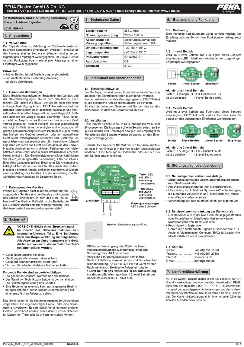
Honeywell PEHA Easyclick 453 FU-RPP o.T User manual

Honeywell

Honeywell PEHA Easyclick 453 FU-RPP o.T User manual

Honeywell MA-LCD Specification sheet

Honeywell

Honeywell MA-LCD Specification sheet

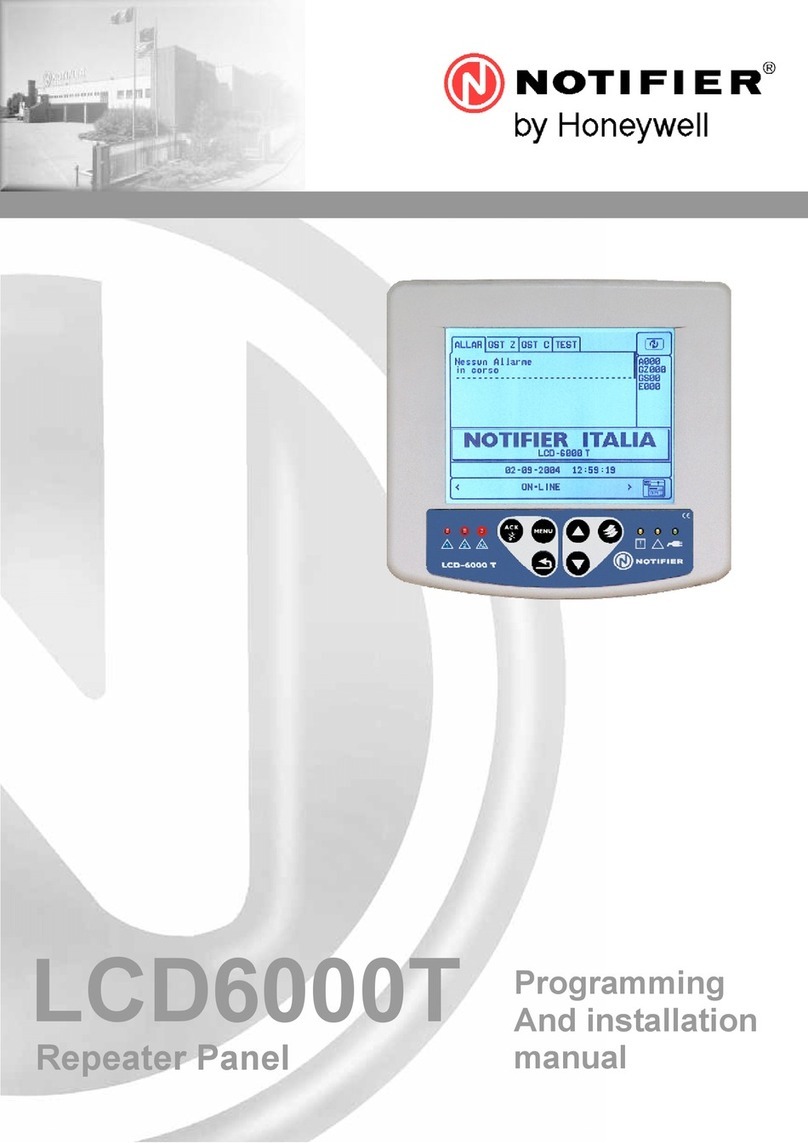
Honeywell NOTIFIER LCD6000T User manual

Honeywell

Honeywell NOTIFIER LCD6000T User manual

Honeywell BRDG-02M11 User manual

Honeywell

Honeywell BRDG-02M11 User manual

Honeywell TB-RP5000W User manual

Honeywell

Honeywell TB-RP5000W User manual

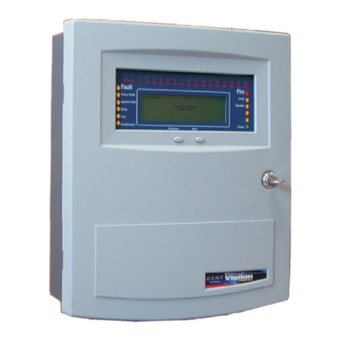
Honeywell GENT VIG-RPT-72 User manual

Honeywell

Honeywell GENT VIG-RPT-72 User manual

Honeywell Notifier IDR-2P User manual

Honeywell

Honeywell Notifier IDR-2P User manual

Honeywell ADEMCO 5800RP User manual

Honeywell

Honeywell ADEMCO 5800RP User manual

Popular Repeater manuals by other brands

Yaesu WIRES-X FT3D instruction manual

Yaesu

Yaesu WIRES-X FT3D instruction manual

Hirschmann OZD Profi 12M manual

Hirschmann

Hirschmann OZD Profi 12M manual

FeinTech VMR00100 manual

FeinTech

FeinTech VMR00100 manual

Asus RP-AC55 quick start guide

Asus

Asus RP-AC55 quick start guide

UGMO PROHOME PH100WR installation manual

UGMO

UGMO PROHOME PH100WR installation manual

Computer Dynamics HDMI-11CA Operation manual

Computer Dynamics

Computer Dynamics HDMI-11CA Operation manual

Satel micra MRU-300 Quick installation guide

Satel

Satel micra MRU-300 Quick installation guide

Icom CY 6000 instruction manual

Icom

Icom CY 6000 instruction manual

Black Box 4-Port BNC Repeater Installation and user guide

Black Box

Black Box 4-Port BNC Repeater Installation and user guide

Icom iFR5000 instruction manual

Icom

Icom iFR5000 instruction manual

Black Box IC496A-R2 manual

Black Box

Black Box IC496A-R2 manual

Icom IC-FR3000 Series Service manual

Icom

Icom IC-FR3000 Series Service manual

Icom IC-FR5000 Series Sales handbook

Icom

Icom IC-FR5000 Series Sales handbook

Black Box DKM SERIES user manual

Black Box

Black Box DKM SERIES user manual

Data Video VP-300R instruction manual

Data Video

Data Video VP-300R instruction manual

Icom IC-FR4000 Series Service manual

Icom

Icom IC-FR4000 Series Service manual

GM International D1033D instruction manual

GM International

GM International D1033D instruction manual

Paradox Hellas S.A. Matrix 2000 Installation and operation manual

Paradox Hellas S.A.

Paradox Hellas S.A. Matrix 2000 Installation and operation manual

manuals.online logo
manuals.online logoBrands
  • About & Mission
  • Contact us
  • Privacy Policy
  • Terms and Conditions

Copyright 2025 Manuals.Online. All Rights Reserved.