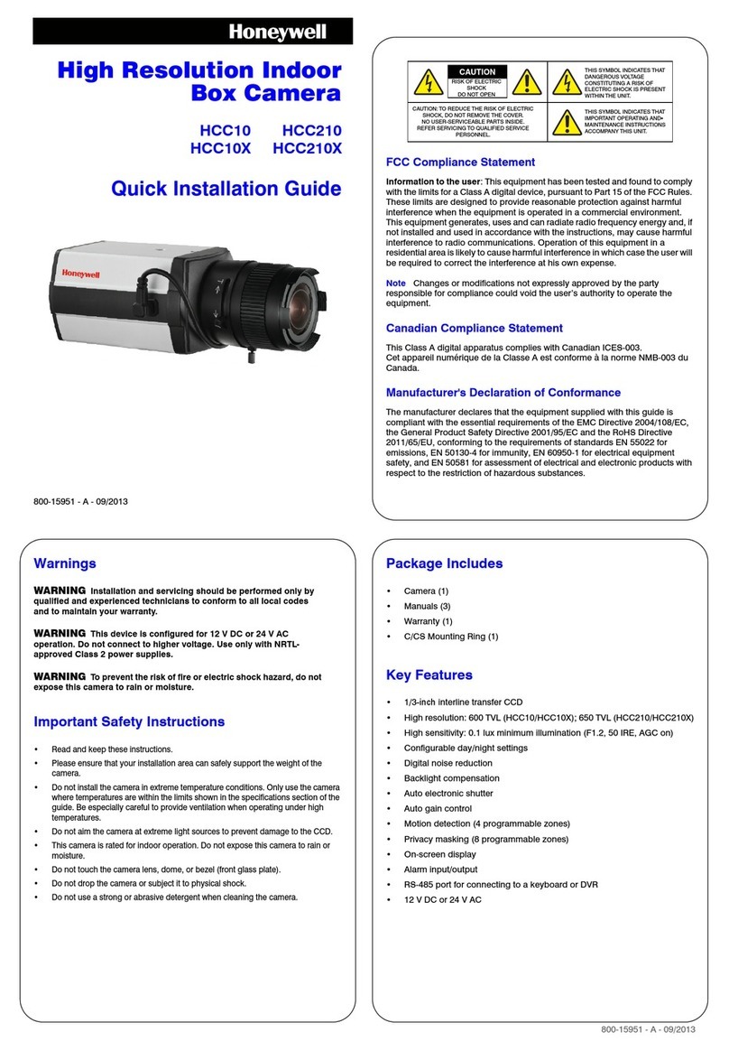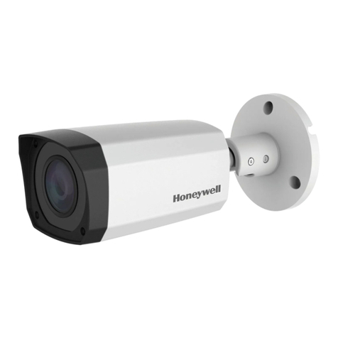
HEC12
Quick Install Guide
Guide d’installation rapide du Caisson
Guia de Instalación de la Carcasa
Guida di Installazione Rapida
Manual de Instalação Rápida
Kurzanleitung
Handleiding voor snelle installatie
Figures
Figure 1 Installation components / Installation des composants /
Componentes de instalación / Compnenti di installazione
Figure 2 Wiring connections / Branchement des câblage / Conexions de
cableado / Connessione dei cavi
Figure 3 4S electrical box installation / Installation sur un coffret de
branchement 4S / Instalación de la caja eléctrica 4S / Installazione
della centralina elettrica 4S
Figure 4 Surface mount installation / Installation en surface / Instalación en
superficie / Installazione con montaggio non ad incasso
Figure 5 Flush mount installation / Installation pour fixation encastrée /
Instalación empotrada / Installazione con montaggio ad incasso
Figure 6 Enclosure cover installation / Installation du couvercle du caisson /
Instalación empotrada / Instalazione copertura involucro
Figure 7 Dome replacement / Remplacement du dôme / Reemplazo del
domo / Sostituzione del dome
HEC12 base
Base HEC12
Base de la HEC12
Base HEC12
Adapter plate
Plaque d’adaptation
Placa adaptadora
Piastra di giunzione
Gimbal (shipped separately)
Cardan (expédié à part)
Cardán (empacado por aparte)
Sospensione cardanica (fornita separatamente)
HEC12 dome enclosure
HEC12 Dôme
Domo de la HEC12
Involucro del dome HEC12
Removable breakaway tab
Languette détachable
Lengüeta desprendible
Linguetta removibile
Junction box (not supplied)
Boîte de raccordement (non fourni
Caja el eléctrica (no incluida)
Scatola di giunzione (non fornita)
Skirt—use with surface mount installation
Embase de blindage—utilisée pour une
installation en surface
Falda—use cuando se instala en
superficie
Collare di rinforzo—da utilizzare con le
installazioni a montaggio non ad incasso
UTP cables
Câbles UTP
Cables UTP (par trenzado no blindado)
Cavi UTP
Coaxial cables
Câbles coaxiaux
Cables coaxiales
Cavi coassiali
Power
Alimentation
Potencia
Alimentazione
Video: female BNC wire
Vidéo: câble BNC femelle
Video: cable hembra BNC
Video: femmina Cavo BNC
red +
rouge +
rojo +
rosso +
black -
noir -
negro -
nero -
Video: Unshielded Twisted Pair wire
Vidéo: Fil à paire torsadée non blindée
Video: Cable de par trenzado, no blindado
Video: non schermati Cavo a coppia intrecciata
Power: 2.1 mm male jack center pin
Alimentation: Prise mâle à broche centrale 2,1 mm
Potencia: Enchufe macho pin centrla de 2,1 mm
Alimentazione 2,1 mm jack maschio a pin centrale
4S electrical box (not supplied)
Coffret de branchement 4S (non fourni)
Caja eléctrica 4S (no incluida)
Centralina eletrica 4S (non in dotazione)
Adapter plate (use is optional)
Plaque d’adaptation (utilisation
optionnelle)
Placa adaptadora (uso opcional)
Piastra di guinzione (l’utilizzo è
opzionale)
HEC12 base
Base HEC12
Base de la HEC12
Base HEC12
#8-32 x 3/8 inch machine screws (x3)
Vis à métal n° 8-32 de 3/8 (x3)
Tornillos 8-32 x 3/8 de pulgada (x3)
Le viti senza dado 8-32 x 3/8” (x3)
!
"
Skirt
Embase de blindage
Falda
Collare di rinforzo
Adapter plate (for mounting to ceiling tile)
Plaque d’adaptation (lorsque le modèle est
fixé à un carreau du plafond)
Placa adaptadora (en instlaaciones en el cielo
raso)
Piastra di guinzione (per utilizzo è opzionale)
HEC12 base
Base HEC12
Base de la HEC12
Base HEC12
Removable breakaway tab for cable
Languette détachable pour câble
Lengüeta desprendible para cable
Linguetta removibile per cavo
"
!
#8-32 x 3/8 inch machine screws (x3)
Vis à métal n° 8-32 de 3/8 (x3)
Tornillos 8-32 x 3/8 de pulgada (x3)
Le viti senza dado 8-32 x 3/8” (x3)
#
Wiring, cabling
Câblage
Alambres, cables
Fili, cablagio
Adapter plate (for mounting to ceiling tile)
Plaque d’adaptation (lorsque le modèle est fixé
à un carreau du plafond)
Placa adaptadora (en instalaciones en el cielo
raso)
Piastra di guinzione (per montaggio su
piastrelle)
HEC12 base
Base HEC12
Base de la HEC12
Base HEC12
"
!
#8-32 x 7/16 inch security screws (x3)
Vis de sécurité n° 8-32 de 7/16 (x3)
Tornillos de seguridad 8-32 x 7/16 (x3)
Viti di sicurezza 8-32 x 7/16” (x3)
HEC12 base
Base HEC12
Base de la HEC12
Base HEC12
Dome enclosure
Dôme
Domo
Involucro del dome
8-32 x 7/16 inch captive security screws
(x3)
Vis de sécurité n° 8-32 de 7/16 (x3)
Tornillos de seguridad 8-32 x 7/16 (x3)
Viti di blocco di sicurezza 8-32 x 7/16”
(x3)
Front cover
Couvre-joint frontal
Placa frontal
Copertura anteriore
Polycarbonate dome
Dôme en polycarbonate
Domo de policarbonato
Dome in policarbonato
Gasket
Joint statique
Sello
Anello di tenuta
Retainer plate
Plaque de retenue
Placa de retención
Piastra di blocco
8-32 x 3/8 inch Hi-lo tapping screws (x3)
Vis taraudeuses Hi-Lo n° 8-32 de 3/8 (x3)
Tornillos de fijación Hi-Lo 8-32 x 3/8 (x3)
Viti maschianti Hi-Lo 8-32 x 3/8” (x3)
English
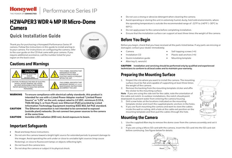
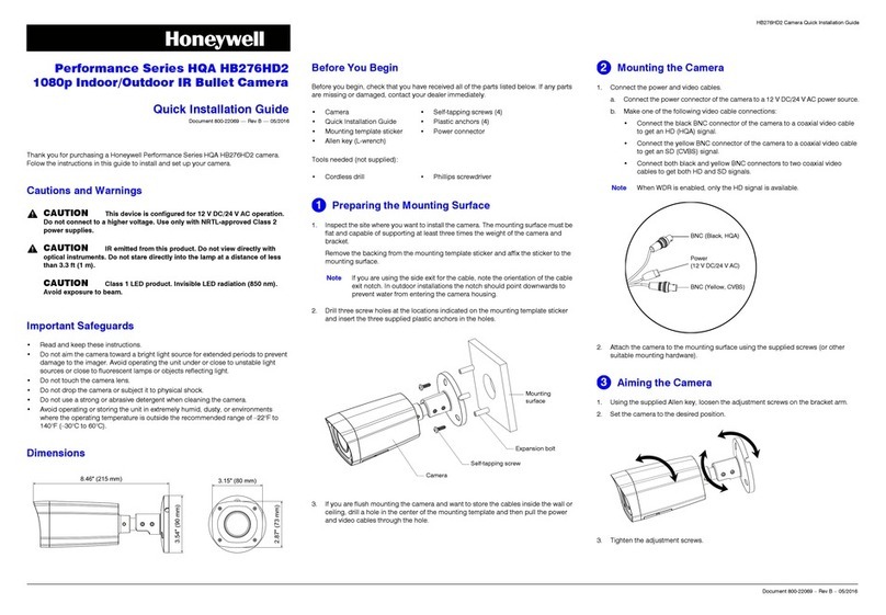
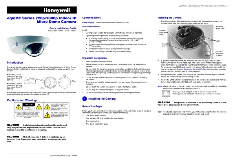
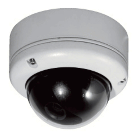
The HEC12 comprises a housing, a gimbal, and a quick change lens.
To complete the installation:
1. Install the housing. Follow the instructions in this guide.
2. Install the gimbal. Refer to the Gimbal Quick Install Guide that
comes with the gimbal (green box).
3. Install the lens. Refer to the Lens Quick Install Guide that comes
with the lens (blue box).
4. Install the enclosure cover. Follow the instructions in this guide.
Important safeguards
Installation and servicing should be done by qualified technicians to
conform to all local codes and to maintain your warranty.
Before you begin
Unpack everything. Check that the items received match those listed on
the order form and packing slip. The HEC12 packing box should
include, in addition to this Quick Install Guide:
• One HEC12 enclosure
• One hardware kit
• One Product Warranty card
If any parts are missing or damaged, contact the dealer you purchased
the camera from or call Honeywell Customer Service.
Installation overview
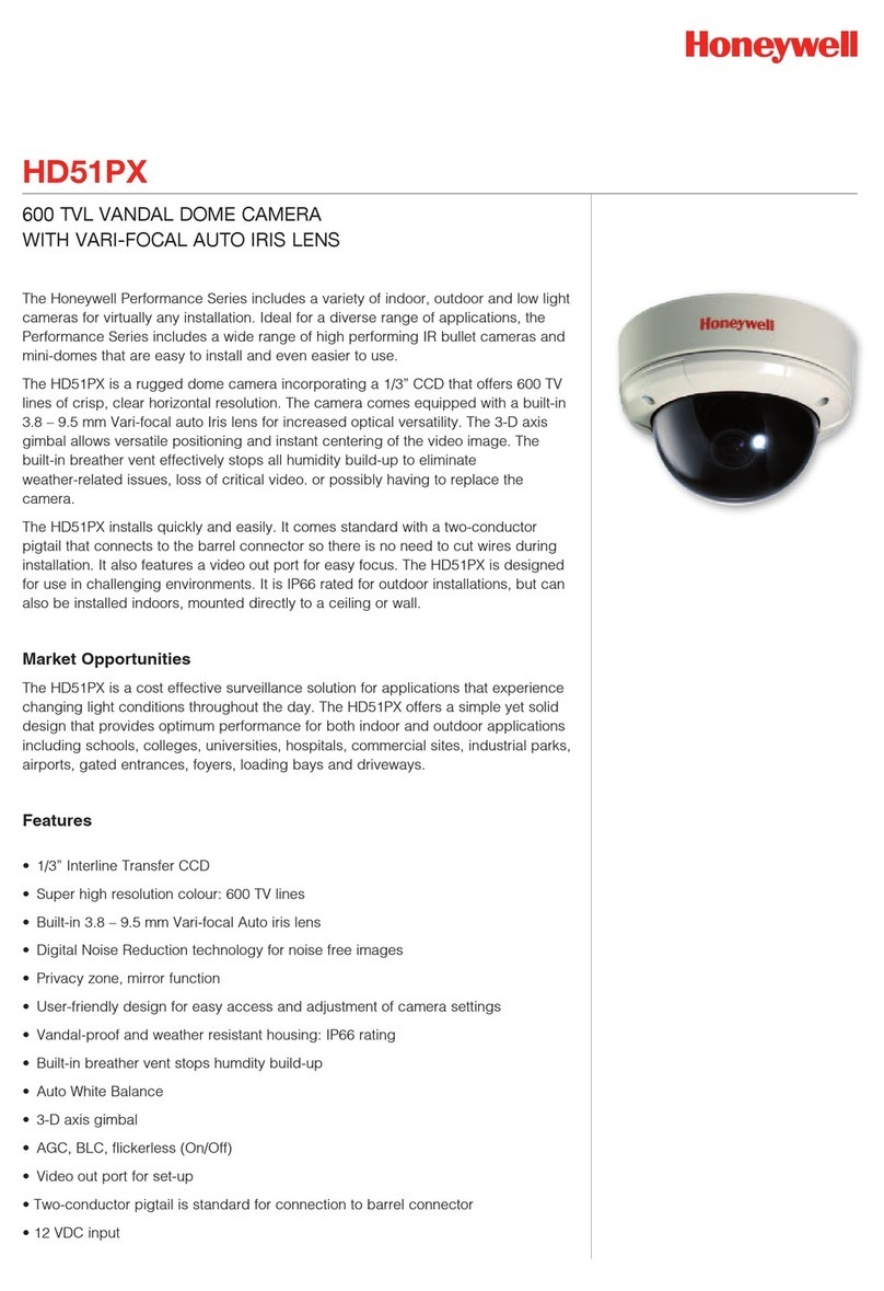
The HEC12 Series Camera is designed to be flush mounted on a wall or
ceiling. The HEC12 is weather-sealed for indoor or outdoor locations.
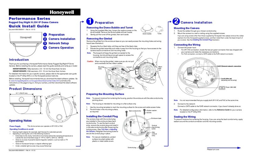
Your HEC12 installation kit (see Figure 1) comes with an adapter plate
that can be used to provide the most flexible mounting options.
1 Wiring connections
Follow Figure 2 to connect the video and power cables.
Note For secure installations, surface-mounted cables
should be protected by plastic or metal cable covers.
Cable guidelines
2 Mounting options
Mount directly to a 4S electrical box
1. Follow Figure 3 to mount the HEC12 directly to a 4S electrical box.
2. The optional adapter plate can be used to cover ceiling or wall
imperfections around the electrical box opening. Secure the
optional adapter plate to the 4S electrical box using appropriate
screws (not supplied).
3. Secure the HEC12 base with #8-32 x 3/8 inch machine screws
(not supplied).
Surface mount
1. Follow Figure 4 to mount the HEC12 to a ceiling or wall.
2. For adapter plate installations, secure the skirt with #8-32 x 7/8
inch pan head screws (x3) supplied.
When not using the adapter plate, use screws appropriate to your
installation (not supplied).
3. Secure the HEC12 base with #8-32 x 3/8 inch machine screws
(x3) supplied.
Flush mount
1. Follow Figure 5 to mount the HEC12 flush to a ceiling or wall.
2. For adapter plate installations, secure the HEC12 base with the
#8-32 x 7/8 inch pan head screws (x3) supplied.
When not using the adapter plate, use screws appropriate to your
installation (not supplied).
3 Next steps
1. Install the gimbal. Refer to the Gimbal Quick Install Guide that
comes with the gimbal (green box).
2. Install the lens. Refer to the Lens Quick Install Guide that comes
with the lens (blue box).
4 Secure the cover
Slide the HEC12 dome enclosure to the base with three #8-32 x 7/16
inch security screws. See Figure 6.
Your camera is ready to go to work for you.
Dome maintenance
Use regular liquid cleaners to remove dirt and grime from the HEC12
dome.
Caution Do not use harsh or abrasive cleaners that can scratch
the polycarbonate dome and reduce visibility for the
camera.
If the camera view is obstructed by scratches, remove the front plate
and rotate to find a part of the dome that is unscratched.
Dome replacement
If the polycarbonate dome is damaged or scratched beyond use,
contact your distributor or salesperson to order a dome replacement.
To replace the HEC12 dome (see Figure 7):
1. Use the security hex key (supplied) to loosen the three #8-32 x 7/
16 inch security screws securing the HEC12 lid to the base.
2. Use a Phillips screwdriver to remove the three #8-32 x 3/8 inch Hi-
lo tapping screws that attach the dome retainer plate to the front
cover.
3. Remove the damaged dome and replace it with the new dome.
4. Use a Phillips screwdriver to attach the dome retainer plate to the
HEC12 front plate with the screws you removed in step 2.
5. Use the security hex key to secure the HEC12 lid to the base.
RISK OF ELECTRIC
SHOCK
DO NOT OPEN
CAUTION: TO REDUCE THE RISK OF ELECTRIC
SHOCK, DO NOT REMOVE THE COVER.
NO USER-SERVICEABLE PARTS INSIDE
REFER SERVICING TO QUALIFIED
SERVICE PERSONNEL
THIS SYMBOL INDICATES THAT
DANGEROUS VOLTAGE
CONSTITUTING A RISK OF
ELECTRIC SHOCK IS PRESENT
WITHIN THE UNIT.
THIS SYMBOL INDICATES THAT
IMPORTANT OPERATING AND
MAINTENANCE INSTRUCTIONS
ACCOMPANY THIS UNIT.
CAUTION
WARNING!
The use of a CSA Certified/UL Listed Class 2 power
supply is required to ensure compliance with
electrical safety standards.
Power supply cable maximum length (feet/meters)
Cameras with AC/DC power supplies
Wire gauge
Power
supply 24
AWG 22
AWG 18
AWG 16
AWG
15 VDC 45/14 73/22 185/56 295/90
24 VAC 408/125 660/201 1674/510 2664/812
Note Calculations are based on an unregulated linear power supply which
would be the worst case. Using a regulated or switching power supply can increase
the cable distance. Honeywell recommends using a CSA Certified/UL listed
Class 2 power supply to ensure compliance with electrical safety standards.
Coaxial video cable maximum length (feet/meters)
Cable type RG-59RG-6RG-11
Wire gauge 23 AWG* 18 AWG* 14 AWG*
Maximum length 750/229 1500/457 2000/610
* Copper clad steel core, 95% braided shield
UTP video cable maximum length (feet/meters)
Honeywell recommends the following NVT video transceivers (sold separately
through NVT Inc.):
• NV-212A (500 ft/152 m—26 Ω)**
• NV-213A/A-M (1000 ft/305 m—52 Ω)**
• NV-652R, NV-862R or NV-1662R (3000 ft/914 m—163 Ω)**
** Distances have been calculated using 24 AWG Twisted Pair wire.
Note We recommend that you measure the wire distance to ensure that the
capability of the twisted pair product is not exceeded. You can measure wire
resistance with an ohmmeter by shorting the two conductors together at the far
end, then measuring the loop resistance out and back. Compare against the
following table.
Maximum length (feet/meters)
AWG 250/
76 500/
152 1000/
305 1500/
457 2000/
610 3000/
914
18 3 Ω6 Ω13 Ω19 Ω26 Ω40 Ω
20 5 Ω10 Ω20 Ω30 Ω40 Ω59 Ω
22 8 Ω17 Ω33 Ω48 Ω66 Ω99 Ω
24 13 Ω26 Ω52 Ω78 Ω108 Ω163 Ω
Note Use point-to-point Unshielded Twisted Pair wire only.
Français
Le modèle HEC12 comporte un caisson, un cardan et un objectif à
changement rapide. Les étapes pour l’installation sont les suivantes :
1. Installez le caisson. Suivez les instructions figurant dans ce guide.
2. Installez le cardan. Pour ce faire, consultez le Guide d’installation
rapide du cardan, livré avec celui-ci (boîte verte).
3. Installez l’objectif. Pour ce faire, consultez le Guide d’installation
rapide de l’objectif, livré avec celui-ci (boîte bleue).
4. Fixez le couvercle du caisson. Suivez les instructions figurant
dans ce guide.
Consignes importantes de sécurité
L’installation et l’entretien doivent être effectués par des techniciens
agréés pour veiller au respect de tous les codes locaux et pour
maintenir vos droits à bénéficier de la garantie.
Instructions préliminaires
Déballez l’ensemble des éléments. Vérifiez que les articles reçus
correspondent à ceux répertoriés sur le bon de commande et sur le
bordereau d’emballage. La boîte du caisson du HEC12 doit
comprendre, en plus de ce guide d’installation rapide :
• Un caisson HEC12
• Une trousse d’installation du caisson HEC12
• Une carte de garantie du produit
Si certaines pièces manquent ou sont endommagées, contactez le
distributeur auprès duquel vous avez acheté la caméra ou appelez le
service clientèle de Honeywell.
Survol de l’installation
La caméra de la série HEC12 est conçue pour être encastrée ou
installée en surface dans un mur ou un plafond. Elle est étanche et peut
donc être installée à l’intérieur comme à l’extérieur. La trousse
d’installation pour votre caméra HEC12 (voir Figure 1) comprend une
plaque d’adaptation qui peut être utilisée pour offrir un maximum
d’options de montage.
1 Branchement des câbles
Suivez les directives de la Figure 2 pour brancher les câbles vidéo et
d’alimentation.
Remarque Pour assurer la sécurité de l’installation, les câbles
montés en surface doivent être protégés par des envel-
oppes de câble métalliques ou en plastique.
Directives concernant les câbles
2 Options de montage
Fixation directe à un coffret de branchment 4S
1. Suivez les directives de la Figure 3 pour fixer le modèle HEC12
directement à un coffret de branchement 4S.
2. La plaque d’adaptation optionnelle peut être utilisée pour couvrir
les imperfections du mur ou du plafond autour de l’ouverture du
coffret de branchement. Fixez la plaque d’adaptation optionnelle
au coffret de branchement 4S à l’aide de vis adaptées à
l’installation (non fournies).
3. Fixez la base du caisson HEC12 avec les trois vis à métal n° 8-32
de 3/8 po. fournies.
Installation en surface
1. Suivez les directives de la Figure 4 pour fixer le modèle HEC12 à
un plafond ou à un mur.
2. Pour les installations utilisant la plaque d’adaptation, fixez
l’embase de blindage avec les trois vis à tête cylindrique bombée
n° 8-32 de 7/8 po. fournies.
Pour les installations qui n’utilisant pas la plaque d’adaptation,
utilisez des vis adaptées à votre installation (non fournies).
3. Fixez la base du caisson HEC12 avec les trois vis à métal n° 8-32
de 3/8 po. fournies.
Installation encastrée
1. Suivez les directives de la Figure 5 pour fixer le modèle HEC12 à
un plafond ou à un mur.
2. Pour les installations utilisant la plaque d’adaptation, fixez la base
du caisson HEC12 avec les trois vis à tête cylindrique bombée n°
8-32 de 7/8 po. fournies.
Pour les installations qui n’utilisant pas la plaque d’adaptation,
utilisez des vis adaptées à votre installation (non fournies).
3 Étapes suivantes
1. Installez le cardan. Pour ce faire, consultez le Guide d’installation
rapide du cardan, livré avec celui-ci (boîte verte).
2. Installez l’objectif. Pour ce faire, consultez le Guide d’installation
rapide de l’objectif, livré avec celui-ci (boîte bleue).
4 Fixer le couvercle
Fixez le dôme du modèle HEC12 à la base avec trois vis de sécurité n°
8-32 de 7/16 po. Voir Figure 6.
Votre caméra est prête à l’usage.
Entretien du dôme
Utilisez un produit nettoyant liquide non abrasif ordinaire pour retirer la
poussière et la saleté du dôme HEC12.
Mise en garde N’utilisez pas de produits nettoyants puissants ou
abrasifs qui risquent de rayer le dôme en
polycarbonate et de réduire la visibilité de la
caméra.
Si des rayures apparaissent dans le champ de la caméra, retirez le
couvre-joint frontal et faites-le tourner jusqu’à ce que vous trouviez une
partie non rayée sur le dôme.
Remplacement du dôme
Si le dôme en polycarbonate est endommagé ou rayé au point d’être
inutilisable, contactez votre distributeur ou un représentant des ventes
pour en commander un autre. Pour remplacer le dôme HEC12 (voir
Figure 7):
1. Utilisez la clé hexagonale de sécurité (fournie) pour retirer les trois
vis de sécurité n° 8-32 de 7/16 po fixant le dôme HEC12 à la base.
2. Utilisez un tournevis à tête cruciforme pour retirer les trois vis
taraudeuses Hi-Lo n° 8-32 de 3/8 po qui fixent la plaque de
retenue du dôme au couvre-joint frontal.
3. Retirez le dôme endommagé et remplacez-le par le nouveau.
4. Utilisez un tournevis à tête cruciforme pour attacher la plaque de
retenue du dôme au couvre-joint frontal de la caméra HEC12 avec
les vis que vous avez retirées à l’étape 2.
5. Utilisez la clé hexagonale de sécurité pour fixez le dôme HEC12 à
la base.
RISQUE DE CHOC
ÉLECTRIQUE.
NE PAS OUVRIR
ATTENTION: POUR RÉDUIRE LE RISQUE DE CHOC
ÉLECTRIQUE, NE RETIREZ PAS LE COUVERCLE.
AUCUNE PIÈCE DONT L’ENTRETIEN PEUT ÊTRE
ASSURÉ PAR L’UTILISATEUR NE SE TROUVE À
L’INTÉRIEUR. CONFIEZ LA MAINTENANCE À DES
TECHNICIENS QUALIFIÉS SPÉCIALISÉS DANS
L’ENTRETIEN
CE SYMBOLE INDIQUE QU’À
L’INTERIEUR DE CETTE UNITÉ PASSE
UN COURANT DE TENSION
SUFFISAMMENT ÉLEVÉE POUR RISQUE
DE PROVOQUER UN CHOC
ÉLECTRIQUE.
CE SYMBOLE INDIQUE QUE
D’IMPORTANTES INSTRUCTIONS
CONCERNANT LE FONCTIONNEMENT
ET LA MAINTENANCE ACCOMPAGNENT
CETTE UNITÉ.
ATTENTION
MISE EN GARDE!
Vous devez utiliser un adaptateur de courant de
classe 2, certifié CSA/homologué UL, pour assurer le
respect des normes de sécurité sur l’électricité.
Longueur maximale des câbles d’alimentation électrique (pieds/mètres)
Caméras dotées d’une alimentation électrique ca/cc
Calibre de fil
Type
d’alimentation 24
AWG 22
AWG 18
AWG 16
AWG
15 VDC 45/14 73/22 185/56 295/90
24 VAC 408/125 660/201 1674/510 2664/812
Remarque Les calculs sont basés sur le cas le plus défavorable, à savoir celui
d’une alimentation électrique linéaire non régulée. L’utilisation d’une alimentation
électrique régulée ou à découpage peut permettre d’augmenter la longueur de
câble. Honeywell recommande l’utilisation d’une alimentation de classe 2, certifié
CSA/homologué UL, pour assurer le respect des normes de sécurité électrique.
Longueur maximale des câbles vidéo coaxiaux (pieds/mètres).
Longueur maximale des câbles vidéo coaxiaux (pieds/mètres)
Type de câble RG-59 RG-6 RG-11
Calibre de fil 23 AWG* 18 AWG* 14 AWG*
Longeur maximale 750/229 1500/457 2000/610
* Âme d’acier recouvert de cuivre, blindage tressé à 95%
Longueur maximale des câbles vidéo UTP (pieds/mètres)
Honeywell recommande l’utilisation des émetteurs-récepteurs vidéo NVT suivants
(vendus séparément par NVT Inc.):
• NV-212A (500 pi/152 m—26 Ω)**
• NV-213A/A-M (1000 pi/305 m—52 Ω)**
• NV-652R, NV-862R or NV-1662R (3000 pi/914 m—163 Ω)**
** Les longueurs ont été calculées en utilisant un fil à paire torsadée de calibre 24
AWG.
Remarque Les longueurs ont été calculées en utilisant un fil à paire torsadée de
calibre 24 AWG.Nous vous recommandons de mesurer la longueur du fil afin de
vous assurer que le système n’excède pas les capacités du produit à paire
torsadée. Vous pouvez mesurer la résistance du fil à l’aide d’un ohmmètre en
court-circuitant les deux conducteurs à l’extrémité distante, puis en mesurant la
résistance de la boucle dans un sens puis dans l’autre. Comparez vos résultats au
tableau suivant.
Longueur maximale (pieds/metres)
AWG 250/
76 500/
152 1000/
305 1500/
457 2000/
610 3000/
914
18 3 Ω6 Ω13 Ω19 Ω26 Ω40 Ω
20 5 Ω10 Ω20 Ω30 Ω40 Ω59 Ω
22 8 Ω17 Ω33 Ω48 Ω66 Ω99 Ω
24 13 Ω26 Ω52 Ω78 Ω108 Ω163 Ω
Remarque Utilisez uniquement un fil UTP point à point.
Español
La unidad HEC12 comprende una carcasa, un cardán y un lente de
cambio rápido. Para efectuar la instalación:
1. Instale la carcasa siguiendo las instrucciones de esta guía.
2. Instale el cardán. Consulte la Guía de Instalación Rápida del
Cardán incluida con el cardán en la caja verde.
3. Instale el lente. Consulte la Guía de Instalación Rápida del Lente
incluida con el lente en la caja azul.
4. Asegure la cubierta de la caja protectora siguiendo las
instrucciones de esta guía.
Precauciones importantes
Para mantener la garantía vigente y cumplir con todos los códigos
locales, la instalación y el servicio a la unidad deben ser realizados sólo
por técnicos certificados.
Antes de comenzar
Desempaque todo. Confirme que los artículos recibidos corresponden
a los indicados en el formulario de pedido y la lista de empaque. La
caja del HEC12 debe incluir, además de esta Guía de Instalación
Rápida:
• Una caja de protección para la cámara HEC12
• Un kit de instalación para la HEC12
• Una tarjeta de Garantía de Producto
Si hacen falta partes o si hay partes dañadas, contacte al distribuidor
donde compró la cámara o llame al departamento de Atención a
Clientes de Honeywell.
Descripción general
La cámara serie HEC12 ha sido diseñada para ser empotrada en la
pared o del cielo raso. La cámara HEC12 esta sellada herméticamente
para poder usarla en interiores o exteriores. El kit de instalación (vea la
Figura 1) incluye una placa adaptadora de uso opcional, que ofrece
opciones de instalación más flexibles.
1 Conexiones de cableado
Siga las indicaciones de la Figura 2 para conectar los cables de video y
de potencia.
Nota Para que la instalación sea segura, los cables instalados
en la superficie deben ser protegidos por tubos porta-
cables plásticos o metálicos.
Pautas para cables
2 Opciones de instalación
Instalar directamente a una caja eléctrica 4S
1. Siga las indicaciones de la Figura 3 para instalar la cámara HEC12
directamente a una caja eléctrica 4S.
2. Se puede usar la placa adaptadora opcional para cubrir cualquier
imperfección en la pared o en el cielo raso alrededor de la
apertura de la caja eléctrica. Asegure la placa adaptadora
(opcional) a la caja eléctrica 4S utilizando tornillos apropriados
(no incluídos).
3. Asegure la base de la HEC12 con los tornillos #8-32 x 3/8 de
pulgada (x3) incluídos.
Instalación en la superficie
1. Siga las indicaciones de la Figura 4 para instalar la unidad HEC12
en el cielo raso o en la pared.
2. En caso de utilizar la placa adaptadora en su instalación, asegure
la falda con los tornillos #8-32 x 7/8 de pulgada (x3) incluidos.
Cuando no utilize la placa adaptadora, utilize tornillos que se
adjusten a las necesidades de su instalación (no incluidos).
3. Asegure la base de la HEC12 con los tornillos #8-32 x 3/8 de
pulgada (x3) incluidos.
Instalación empotrada
1. Siga las indicaciones de la Figura 5 para empotrar la unidad
HEC12 en el cielo raso o en la pared.
2. En caso de utilizar la placa adaptadora en su instalación, asegure
lla base de la HEC12 con los tornillos #8-32 x 7/8 de pulgada (x3)
incluidos.
Cuando no utilize la placa adaptadora, utilize tornillos que se
adjusten a las necesidades de su instalación (no incluidos).
3 Pasos siguientes
1. Instale el cardán. Consulte la Guía de Instalación Rápida del
Cardán incluida con el cardán en la caja verde.
2. Instale el lente. Consulte la Guía de Instalación Rápida del Lente
incluida con el lente en la caja azul.
4 Asegure el domo
Asegure el domo de la unidad HEC12 a su base con los tres tornillos de
seguridad #8-32 x 7/16 de pulgada. Vea la Figura 6.
¡Su cámara esta lista!
Mantenimiento de rutina
Use cualquier detergente líquido común para remover grasa o suciedad
del domo de la HEC12.
Precaución No use limpiadores abrasivos o muy fuertes porque
pueden rayar el domo de policarbonato y reducir la
visibilidad de la cámara.
Si la visión de la cámara está obstruida porque el domo está muy
rayado, saque la placa frontal y dele vuelta hasta encontrar una parte
del domo que no esté rayada.
Para reemplazar el domo
Si el domo de policarbonato se llega a dañar o está rayado de tal forma
que no se pueda usar, contacte a su distribuidor o a su agente de
ventas para pedir un domo de reemplazo. Para instalar el nuevo domo
de la HEC12 (vea Figura 7):
1. Desatornille los tres tornillos de seguridad #8-32 x 7/16 de
pulgada que sostienen la cubierta de la HEC12 en la base con la
llave hexagonal de seguridad provista.
2. Con un destornillador Phillips saque los tres tornillos de fijación Hi
Lo #8-32 x 3/8 de pulgada que aseguran la placa de retención a
la cubierta frontal.
3. Quite el domo dañado e instale el nuevo domo en su lugar.
4. Con un destornillador Phillips vuelva a asegurar la placa de
retención del domo a la placa frontal de la unidad HEC12,
utilizando los tornillos que quitó en el paso 2.
5. Con la llave de seguridad hexagonal, asegurar la cubierta de la
HEC12 a su base.
RIESGO DE CHOQUE
ELÉCTRICO.
NO LO ABRA.
PRECAUCIÓN: PARA REDUCIR EL RIESGO DE
CHOQUES ELÉCTRICOS, NO QUITE LA CUBIERTA.
EL MANTENIMIENTO Y EL SERVICIO DEBEN SER
HECHOS SÓLO POR PERSONAL CALIFICADO.
ESTE SÍMBOLO INDICA QUE
DENTRO DE ESTA UNIDAD HAY
TENSIÓN PELIGROSA QUE
PUEDE CAUSAR CHOQUES
ELÉCTRICOS.
ESTE SÍMBOLO INDICA QUE
INSTRUCCIONES IMPORTANTES
DE FUNCIONAMIENTO Y
MANTENIMIENTO ACOMPAÑAN
ESTA UNIDAD.
CUIDADO
¡ADVERTENCIA!
Es imprescindible utilizar una alimentación de potencia
Clase 2 certificada por CSA o listado por UL para cumplir
con las normas eléctricas de seguridad.
Máxima longitud para el cable de suministro de potencia (pies/metros)
Cámaras con suministro CA/CC
Calibre
Suministro
de potencia AWG
24 AWG
22 AWG
18 AWG
16
15 VCC 45/14 73/22 185/56 295/90
24 VCA 408/125 660/201 1674/510 2664/812
Nota Los cálculos se basan en una alimentación lineal no regulado que sería
el peor escenario. Si utiliza una fuente de alimentación regulada, puede aumentar
la distancia del cable. Honeywell recomienda usar una fuente de alimentación
Certificada por CSA o Clase 2 de UL para asegurar el cumplimiento de las
normas de seguridad eléctricas.
Máxima longitud del cable coaxial de video (pies/metros)
Tipo de cable RG-59 RG-6 RG-11
Calibre 23 AWG* 18 AWG* 14 AWG*
Distancia máxima 750/229 1500/457 2000/610
* Núcleo de accro revestido de cobre, 95% blindaje de malla
Máxima longitud del cable UTP de video (pies/meters)
Honeywell recomienda los siguientes transceptores NVT (vendidos por NVT Inc
por aparte):
• NV-212A (500 pi/152 m—26 Ω)**
• NV-213A/A-M (1000 pi/305 m—52 Ω)**
• NV-652R, NV-862R or NV-1662R (3000 pi/914 m—163 Ω)**
** Las distancias han sido calculadas usando un cable de par trenzado 24 AWG.
Nota Se recomienda medir la distancia del cable para asegurar que no va a
exceder la capacidad del cable de par trenzado. La resistencia del cable se puede
medir con un ohmetro cortocircuitando los dos conductores al mismo tiempo en el
extremo alejado y luego midiendo la resistencia del bucle de ida y de vuelta.
Compare el resultado con la siguiente tabla.
Longitud máxima (pies/metros)
AWG 250/
76 500/
152 1000/
305 1500/
457 2000/
610 3000/
914
18 3 Ω6 Ω13 Ω19 Ω26 Ω40 Ω
20 5 Ω10 Ω20 Ω30 Ω40 Ω59 Ω
22 8 Ω17 Ω33 Ω48 Ω66 Ω99 Ω
24 13 Ω26 Ω52 Ω78 Ω108 Ω163 Ω
Nota Use sólo cable de par trenzado, sin blindaje, de punto a punto.
Italiano
Il modello HEC12 è costituito da un alloggiamento, una sospensione
cardanica e un obiettivo a sostituzione rapida. Per completare
l’installazione:
1. Installare l’alloggiamento. Seguire le istruzioni riportate in questa
guida.
2. Installare la sospensione cardanica. Fare riferimento alla Guida di
installazione rapida della sospensione cardanica in dotazione con
la sospensione cardanica (scatola verde).
3. Installare l’obiettivo. Fare riferimento alla Guida di installazione
rapida dell’obiettivo in dotazione con l’obiettivo (scatola blu).
4. Fissare la copertura dell’involucro. Seguire le istruzioni riportate in
questa guida.
Informazioni importanti per la
sicurezza
L’installazione e la manutenzione devono essere eseguite da tecnici
certificati per la conformità alle norme locali e per mantenere la validità
della garanzia.
Prima di iniziare
Aprire la confezione. Verificare che gli elementi ricevuti corrispondano a
quelli elencati nel modulo d’ordine e nel tagliando della confezione.
Oltre a questa Guida di installazione rapida, la scatola
dell’alloggiamento HEC12 deve comprendere quanto elencato di
seguito:
• Un involucro HEC12
• Un kit hardware
• Una scheda di garanzia del prodotto
Nel caso di parti mancanti o danneggiate, rivolgersi al rivenditore
presso il quale è stata acquistata l’unità o chiamare il Servizio clienti di
Honeywell.
Panoramica sull’instalazione
La videocamera della serie HEC12 è progettata per essere montata ad
incasso su soffitto o parete. È resistente ai fattori ambientali esterni per
l’utilizzo in luoghi all’aperto o al chiuso. Il kit di installazione HEC12
(vedere Figura 1) include una piastra di giunzione che può essere
utilizzata per fornire opzioni di montaggio flessibili.
1 Collegamento cavi
Fare riferimento alla Figura 2 per collegare i cavi di alimentazione e
video.
Nota Per un’installazione in condizioni di sicurezza, i cavi
montati in superficie devono essere protetti da un
rivestimento cavi in metallo o plastica.
Istruzioni per i cavi
2 Opzioni di montaggio
Montare direttamente su una centralina
elettrica 4S
1. Fare riferimento alla Figura 3 per le modalità di montaggio del
modello HEC12 direttamente su una centralina elettrica 4S.
2. La piastra di giunzione opzionale può essere utilizzata per coprire
eventuali imperfezioni del soffitto o parete circostanti l’apertura
della centralina elettrica. Fissare la piastra di giunzione alla
centralina elettrica 4S utilizzando le viti apposite (non fornite).
3. Fissare la base HEC12 con le viti senza dado 8-32 x 3/8" (x3) in
dotazione.
Montaggio non ad incasso
1. Fare riferimento alla Figura 4 per le modalità di montaggio del
modello HEC12 su un soffitto o parete.
2. Per l’installazione della piastra di giunzione, fissare il collare di
rinforzo con le viti a testa orientabile 8-32 x 7/8" (x3) in dotazione.
Quando non si utilizza la piastra di giunzione, usare le viti adatte
all’installazione (non fornite).
3. Fissare la base HEC12 con le viti senza dado 8-32 x 3/8" (x3) in
dotazione.
Montatura ad incasso
1. Fare riferimento alla Figura 5 per le modalità di montaggio ad
incasso del modello HEC12 su un soffitto o parete.
2. Per l’installazione della piastra di giunzione, fissare la base HEC12
con le viti a testa orientabile 8-32 x 7/8" (x3) in dotazione.
Quando non si utilizza la piastra di giunzione, usare le viti adatte
all’installazione (non fornite).
3 Passaggi successivi
1. Installare la sospensione cardanica. Fare riferimento alla Guida di
installazione rapida della sospensione cardanica in dotazione con
la sospensione cardanica (scatola verde).
2. Installare l’obiettivo. Fare riferimento alla Guida di installazione
rapida dell’obiettivo in dotazione con l’obiettivo (scatola blu).
4 Fissare la copertura
Far scorrere la cerniera in direzione della base fino ad allineare le viti
con i relativi fori. Bloccare la copertura in posizione. Vedere Figura 6.
La videocamera è pronta per l’utilizzo.
Manutenzione del dome
Utilizzare detergenti liquidi per rimuovere lo sporco e il grasso dal dome
HEC12.
Avvertenza Non utilizzare detergenti abrasivi o troppo aggressivi
che possano graffiare il dome di policarbonato e
ridurre la visibilità della videocamera.
Se la vista della videocamera è ostruita da graffi, rimuovere la piastra
anteriore e ruotare fino a trovare una parte liscia e uniforme.
Sostituzione del dome
Se i danni e i graffi sul dome in policarbonato non rendono possibile il
relativo utilizzo, contattare il rivenditore autorizzato per ordinare un
dome di sostituzione. Per sostituire il dome HEC12 (vedere Figura 7):
1. Utilizzare una chiave esagonale di sicurezza (in dotazione) per
allentare le tre viti di sicurezza num. 8-32 x 7/16" che fissano il
coperchio HEC12 alla base.
2. Utilizzare un giravite Phillips per rimuovere le tre viti maschianti Hi-
lo 8-32 x 3/8" che fissano la piastra di blocco del dome alla
copertura anteriore.
3. Rimuovere il dome danneggiato e sostituirlo con la nuova unità.
4. Utilizzare un giravite Phillips per fissare la piastra di blocco del
dome alla piastra anteriore HEC12 con le viti che sono state
rimosse nel passaggio 2.
5. Utilizzare una chiave esagonale di sicurezza per fissare il
coperchio HEC12 alla base.
RISCHIO DI SCOSSA
ÉLETTRICA
NON APRIRE
ATTENZIONE: PER RIDURRE IL RISCHIO DI SCOSSA
ÉLETTRICA, NON RIMUOVERE
LA COPERTURA. NON CONTIENE PARTI RIPARABILI
DALL’UTENTE. FARE ESEGUIRE LA MANUTENZIONE A
PERSONALE QUALIFICATO.
QUESTO SIMBOLO INDICA LA
PRESENZA DI TENSIONI
PERICOLOSE ALL’INTERNO
DELL’UNITÀ; RISCHIO DI
SCOSSA ÉLETTRICA.
QUESTO SIMBOLO INDICA CHE
L’UNITÀ È ACCOMPAGNATA DA
IMPORTANTI INFORMAZIONIPER
L’USO E LA MANUTENZIONE.
ATTENZIONE
AVVERTENZA!
Si richiede l’utilizzo di alimentatori con certificazione
CSA, classificati UL, classe 2, per la conformità con gli
standard di sicurezza elettrica.
Lunghezza massima cavo di alimentazione (metri)
Videocamere con alimentazione CA/c.c.
Calibratura fili
Alimentazione
elettrica 24
AWG 22
AWG 18
AWG 16
AWG
15V c.c. 45/14 73/22 185/56 295/90
24V CA 408/125 660/201 1674/510 2664/812
Nota I calcoli si basano sull’alimentazione lineare non regolata, che
rappresenta il caso peggiore. L’utilizzo di alimentazione regolata o
a commutazione consente di aumentare la distanza del cavo.
Honeywell consiglia l’utilizzo di alimentatori con certificazione
CSA, classificati UL, classe 2, per la conformità con gli standard
di sicurezza elettrica.
Lunghezza massima cavo video coassiale (metri)
Tipo di cavo RG-59 RG-6 RG-11
Calibratura fili 23 AWG* 18 AWG* 146 AWG*
Lunghezza massima 750/229 1500/457 2000/610
* Anima di acciaio con rivestimento in rame, 95% protezione intrecciata
Lunghezza massima cavo video UTP (metri)
Honeywell consiglia i seguenti ricetrasmettitori video NVT (venduti separatamente
tramite NVT Inc.):
• NV-212A (152 m—26 Ω)**
• NV-213A/A-M (305 m—52 Ω)**
• NV-652R, NV-862R o NV-1662R (914 m—163 Ω)**
** Le distanze sono state calcolate in base al cavo a coppia intrecciata 24 AWG.
Nota Si consiglia di misurare la distanza del cavo per evitare di superare
la capacità del cavo a coppia intrecciata. È possibile calcolare la
resistenza del cavo con un ohmetro cortocircuitando i due
conduttori insieme alle estremità e calcolando quindi la resistenza
in loop di entrata di ritorno. Eseguire un confronto seguendo la
tabella riportata.
Lunghezza massima (metri)
AWG 250/76 500/152 1000/305 1500/457 2000/610 3000/914
18 3 Ω6 Ω13 Ω19 Ω26 Ω40 Ω
20 5 Ω10 Ω20 Ω30 Ω40 Ω59 Ω
22 8 Ω17 Ω33 Ω48 Ω66 Ω99 Ω
24 13 Ω26 Ω52 Ω78 Ω108 Ω163 Ω
Nota Utilizzare solo un cavo a coppia intrecciata punto a punto.
