manuals.online logo
Brands
  1. Home
  2. •
  3. Brands
  4. •
  5. Honeywell
  6. •
  7. Security Camera
  8. •
  9. Honeywell ACUIX User manual

Honeywell ACUIX User manual

Document 800-03542 Rev A
12/08 1
ACUIXTM Fixed Camera Dome:
Single or Double Ball Joint
Stick Mount
Indoor Pendant Housing
Quick Installation Guide
1Introduction
Caution The maximum camera and lens weight that can be
installed in the housing is 2 pounds (0.91 kg).
Note The fixed camera is selected by the end user. Install a
camera with a ¼”-20 tripod mount and ensure that the
size of the camera and lens allow enough room to aim
and adjust the lens within the contraints of the housing.
Note It is the installer’s responsibility to complete the wiring
and required connections based on the camera
selected.
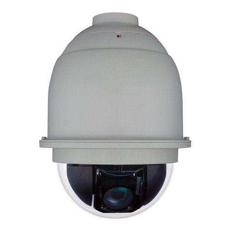
Figure 1 External Dome Layout
2Install the Mount or Adapter
The indoor pendant housing has optional mounts and adapters available.
See Figure 2.
Threaded nipple
Housing
Lower dome
Figure 2 Indoor Mounts and Adapters
2a Installing a Wall Mount and Optional Pole or Corner
Adapters
The HDXWM1 wall mount is designed specifically for the ACUIX and can be
mounted directly to a vertical load-bearing surface. It supports up to 25
pounds (11.7 kg).
Figure 3 Wall Mount Dimensions
1. Route the field wiring as required through the wall, pendant housing
wiring access hole, and then through the wall mount.
Approximately one foot (0.3 m) of cable must extend past the mount for
all installations.
• If installing with a corner or pole adapter also route the field wiring
through the corner or pole adapter hole.
Ceiling Mount
(HDCM1)
Wall Mount
(HDXWM1)
Pole Mount Adapter
(HDXPMA1)
Corner Adapter
(HDXCMA1)
4.13” (105.0 mm)
0.28” diameter
(7.00 mm)
3.94” (100.0 mm)
5.71” (145 mm)
9.84”(250 mm)
ACUIX Stick Mount Quick Installation Guide
2
2. (Optional) If you are installing the wall mount with a corner adapter
(HDXCMA1) or pole mount adapter (HDXPMA1) then:
Pole Adapter
• Secure the pole mounting bracket to the pole using hardware
specifically designed for the surface/material. There are four
cutouts (two on each side), 0.24” x 0.75” (6 mm x 19 mm), to
accommodate straps to secure the pole mounting bracket to a
pole. See Figure 4.
Corner Adapter
• Secure the corner bracket using hardware specifically designed
for the surface/material. The bracket has eight 0.39” (10.0 mm)
holes; four on each side. See Figure 5.
3. (Optional): If you are installing with a corner or pole adapter, line up the
hole pattern on the wall mount with the hole pattern on the corner or
pole adapters.
4. Secure the wall mount to the wall using hardware specifically designed
for the surface. There are four 0.28” (7.00 mm) diameter mounting
holes for securing the mount.
Figure 4 Pole Mount Adapter Dimensions (HDXPMA1)
6.1" (155 mm)
6.69" (170 mm)
1" (25.4 mm)
diameter
4 cutouts (2 on each side)
3.3"(84mm)
55 degrees
4.6" (116.8 mm)
Figure 5 Corner Adapter Dimensions (HDXCMA1)
2b Installing a Ceiling Mount
The ceiling mount is installed directly to a horizontal load-bearing surface
and supports up to 25 pounds (11.7 kg).
1. Route field wiring as required into the wiring access hole and through
the center of the ceiling mount.
Approximately one foot (0.3 m) of cable must extend past the mount.
2. Secure the ceiling mount to the ceiling using hardware specifically
designed for the surface.
There are four 0.47” (12.00 mm) diameter mounting holes for securing
the mount. See Figure 6.
90 degrees
5.43"(138mm)
6.3" (160 mm)
3.94" (100 mm)
6.89" (175 mm)
0.39" (10 mm) diameter (x8 through)
3.54" (90 mm)
1" (25.4 mm) diameter
4.6" (116.8 mm)
Document 800-03542 Rev A
12/08 3
Figure 6 Ceiling Mount Dimensions
3Install the Housing
1. If not already done, route the field wiring:
a. Through the housing mount, then
b. Through the field wiring access hole in the housing, and then
c. Through the field wiring access hole under the base plate (see
Figure 7).
Note The wiring must extend at least one foot (0.3 m) past the
mount for wiring purposes.
2. Install the housing on the mount. Make sure there is Teflon®tape on
the threaded nipple part of the housing.
14.76” (375.0 mm)
5.51” (140.0 mm)
PF 1.5”
3.58" (91.0 mm) 4.57” (116.0 mm)
0.47” (12.0 mm)
diameter
3.54” (90 mm)
4Install and Adjust the Camera Position
Single Ball Joint Stick Mount (HDH4D)
1. Screw the camera onto the 1/4”-20
tripod mounting screw. Keep the
nut on the inside, closest to the ball
socket.
2. Loosen the position screws on the
base plate. See Figure 7.
3. Slide the camera mount in the slot
to position the camera based on the
installation requirements.
4. Tighten the position screws on the
base plate.
5. Loosen the base of the ball socket.
Adjust the camera to the required
angle.
6. Turn the base of the ball socket to tighten and secure the camera
angle.
7. Tighten the camera mounting nut tight against the fixed camera block.
8. Complete the wiring as per the camera selected.
Figure 7 Internal Pendant Housing - Single Ball Joint
Camera mount screw and nut
Ball socket base
Field wiring
access hole
Clip lower dome
lanyard to bracket
Position screws
(1 of 2) in the
base plate
Loosen ball socket base to
adjust camera angle
Camera mount screw
(1/4“-20 tripod) and nut
Base plate slot (1 of 2)
ACUIX Stick Mount Quick Installation Guide
Document 800-03542 – Rev A – 12/08
© 2008 Honeywell International Inc. All rights reserved. No part of this publication may be reproduced by any means without written permission from Honeywell. The information in this publication is believed to be
accurate in all respects. However, Honeywell cannot assume responsibility for any consequences resulting from the use thereof. The information contained herein is subject to change without notice. Revisions or new
editions to this publication may be issued to incorporate such changes.
www.honeywellvideo.com
+1.800.796.CCTV (North America only)
[email protected]
Double Ball Joint Stick Mount (HDH6D)
Note See Figure 8 to complete this step.
1. Screw the camera onto the 1/4”-20 tripod mounting screw. The nut
cannot be loosened and stays on the inside, closest to the ball socket.
2. Grasp the bottom of the double pivot assembly and loosen it from the
base plate.
3. Slide the mount within the two slots to position the camera based on
the installation requirements.
4. Loosen the angle adjustment knobs. Adjust the camera to the required
angle.
5. Tighten all connections and complete the wiring as per the camera
selected.
Figure 8 Double Ball Joint
5Install the Lower Dome
1. Clip the lower dome lanyard to the housing bracket. See Figure 7.
2. Confirm that the o-ring is in place around the lower dome.
3. Press the lower dome into the housing and turn the screws to secure
the lower dome to the housing.
Camera mount
screw (1/4“-20
tripod)
Base plate slots -
bi-directional
Double ball joint assembly - loosen at
base to adjust camera location
Angle adjustment knob (1 of 2)

Other manuals for ACUIX

4

Other Honeywell Security Camera manuals
Honeywell HD60 Series User manual

Honeywell

Honeywell HD60 Series User manual

Honeywell 2450Cm Series User manual

Honeywell

Honeywell 2450Cm Series User manual
Honeywell HD4UX User manual

Honeywell

Honeywell HD4UX User manual

Honeywell KD6A User manual

Honeywell

Honeywell KD6A User manual

Honeywell HDT User manual

Honeywell

Honeywell HDT User manual

Honeywell HCCM474M User manual

Honeywell

Honeywell HCCM474M User manual

Honeywell HZC-755N/P Series User manual

Honeywell

Honeywell HZC-755N/P Series User manual

Honeywell HD4USX User manual

Honeywell

Honeywell HD4USX User manual

Honeywell HCD92534 User manual

Honeywell

Honeywell HCD92534 User manual

Honeywell HBD9 User manual

Honeywell

Honeywell HBD9 User manual

Honeywell IPCAM-WOC1 User manual

Honeywell

Honeywell IPCAM-WOC1 User manual

Honeywell EQUIP Series User manual

Honeywell

Honeywell EQUIP Series User manual

Honeywell equIP Ex-proof Series User manual

Honeywell

Honeywell equIP Ex-proof Series User manual

Honeywell HCC484LX User manual

Honeywell

Honeywell HCC484LX User manual

Honeywell HD4U User manual

Honeywell

Honeywell HD4U User manual

Honeywell VISTA VBC-800PI User manual

Honeywell

Honeywell VISTA VBC-800PI User manual

Honeywell HD70PX User manual

Honeywell

Honeywell HD70PX User manual

Honeywell VSD-361P User manual

Honeywell

Honeywell VSD-361P User manual

Honeywell HD3VC4HR User manual

Honeywell

Honeywell HD3VC4HR User manual

Honeywell HD3UX User manual

Honeywell

Honeywell HD3UX User manual

Honeywell JOSI-DBC012-N11 User manual

Honeywell

Honeywell JOSI-DBC012-N11 User manual

Honeywell HCM574L User manual

Honeywell

Honeywell HCM574L User manual

Honeywell HD28C4HR6 User manual

Honeywell

Honeywell HD28C4HR6 User manual

Honeywell HCD484L User manual

Honeywell

Honeywell HCD484L User manual

Popular Security Camera manuals by other brands

Eneo NTC-4151/PP Installation and operating manual

Eneo

Eneo NTC-4151/PP Installation and operating manual

Novus NVIP-5DN3614V/IR-1P/F user manual

Novus

Novus NVIP-5DN3614V/IR-1P/F user manual

World Eye CLEAR-8MP quick start guide

World Eye

World Eye CLEAR-8MP quick start guide

Riva RC3500M installation guide

Riva

Riva RC3500M installation guide

Vicon Roughneck V894CSHR-VF-C Installation & operation manual

Vicon

Vicon Roughneck V894CSHR-VF-C Installation & operation manual

OPTICOM IR-5625 datasheet

OPTICOM

OPTICOM IR-5625 datasheet

Tokyo Electronic CS3910H Operation manual

Tokyo Electronic

Tokyo Electronic CS3910H Operation manual

Panasonic OneHome KX-HCM110A Service manual

Panasonic

Panasonic OneHome KX-HCM110A Service manual

Platinum CCTV CD-0245 installation instructions

Platinum CCTV

Platinum CCTV CD-0245 installation instructions

Reolink NVS8-5KB4-A Operational Instruction

Reolink

Reolink NVS8-5KB4-A Operational Instruction

EYENIMAL PET VISION LIVE HD user manual

EYENIMAL

EYENIMAL PET VISION LIVE HD user manual

Vivotek FD8366-V Quick installation guide

Vivotek

Vivotek FD8366-V Quick installation guide

Eyeris ERV-L460N operating instructions

Eyeris

Eyeris ERV-L460N operating instructions

LevelOne CamCon FCS-4000 user manual

LevelOne

LevelOne CamCon FCS-4000 user manual

Conceptronic CIPCAMPTIWL user manual

Conceptronic

Conceptronic CIPCAMPTIWL user manual

Weber Protect WP-C199W4 instruction manual

Weber Protect

Weber Protect WP-C199W4 instruction manual

360 Vision Affiniti Thermal IP Installation & configuration manual

360 Vision

360 Vision Affiniti Thermal IP Installation & configuration manual

TBK vision TBK-BUL7443EIR user manual

TBK vision

TBK vision TBK-BUL7443EIR user manual

manuals.online logo
manuals.online logoBrands
  • About & Mission
  • Contact us
  • Privacy Policy
  • Terms and Conditions

Copyright 2025 Manuals.Online. All Rights Reserved.