manuals.online logo
Brands
  1. Home
  2. •
  3. Brands
  4. •
  5. Honeywell
  6. •
  7. Thermostat
  8. •
  9. Honeywell CHRONOTHERM T4700 User manual

Honeywell CHRONOTHERM T4700 User manual

1 XX-XXXX—X
INSTALLATION INSTRUCTIONS
® U.S. Registered Trademark
Copyright © 2003 Honeywell International Inc.
All Rights Reserved 69-1395-1
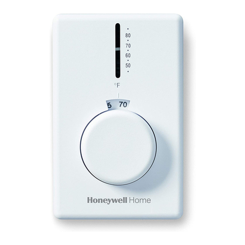
T4700 Chronotherm® Electronic
Programmable Line Voltage
Thermostat
APPLICATION
The T4700A,B Chronotherm® Electronic
Programmable Line Voltage Thermostat provides
exceptional comfort with the flexibility of 7-day
programming and resistance-rated heating
equipment. The patented CoolSwitch™ design
provides a long service life.
Depending on local climate, night and day
temperature setback can save up to 28 percent of
the energy used to heat a controlled zone.
According to the Electric Power Research Institute,
precision temperature control also saves up to
12 percent energy during comfort periods
compared with conventional I-metal electric
heating thermostats.
MERCURY NOTICE
If this control is replacing a control that
contains mercury in a sealed tube, do not
place your old control in the trash. Dispose
of properly.
Contact your local waste management
authority for instructions regarding
recycling and the proper disposal of an old
control. If you have questions, call
Honeywell Customer Response Center
at 1-800-468-1502.
INSTALLATION
When Installing This Product...
1. Read these instructions carefully. Failure to
follow these instructions can damage the
product or cause a hazardous condition.
2. Check the ratings given in the instructions
and on the product to make sure the product
is suitable for your application.
3. Installer must be a trained, experienced ser-
vice technician.
4. After completing installation, use these
instructions to check out the product opera-
tion.
WARNING
240 Vac Line Voltage Hazard.
Can cause serious injury or death.
Disconnect power before making wiring
connections.
Do not install thermostat unless you are
fully competent with house wiring.
Do not connect to voltage different from
device rating.
Location
Install the thermostat away from concealed warm
or cold water pipes, air ducts, or drafts from
hallways, fireplaces or stairways. Do not place the
thermostat above a heater.
1. Select a location for mounting the thermostat
on an inside wall where the thermostat can
be subjected to average room temperature.
2. Install a vertical switch box for mounting the
thermostat approximately 1.5m (5 ft) above
the floor on the inside wall selected.
This is a legacy product document
supported by Resideo. It is no
longer manufactured
T4700 CHRONOTHERM® ELECTRONIC PROGRAMMABLE LINE VOLTAGE THERMOSTAT
XX-XXXX—X 2
69-1395—1 2
Wiring
1. Disconnect power before beginning
installation.
2. Double check that thermostat is rated for the
voltage and amperage of the load to be
controlled.
3. Remove cover by carefully prying at the top
or bottom edge with a coin or slotted
screwdriver; flip open door cover.
4. When replacing an old line voltage wall ther-
mostat, remove it carefully to avoid damag-
ing wiring insulation. Check the old insulation
for cracks, nicks, or fraying and apply
certified electrical tape, as needed, to
achieve adequate insulation, or replace the
wires using standard methods.
5. Attach thermostat wires with solderless wire
connectors approved for the size and
number of wires to be connected. Be sure
that all wire connectors are tight. See Fig. 1.
6. Secure thermostat to the electrical box with
captive mounting screws.
—Installation Hint: Pre-bend the solid con-
ductors, then push them and the wire con-
nectors into the electrical box before
tightening the mounting screws.
7. Snap cover in place; close door cover after
setting the thermostat and turn on the power.
Fig. 1. T4700A,B Thermostat typical hookup.
SETTINGS
Initial Powerup
When the thermostat is first powered up (or after
eight hours of continuous power loss), the display
blinks for two seconds and then undergoes a
self-test — while displays for about 15
seconds.
This is followed by the display flashing (1:00 PM);
the internal checkout is complete and the
thermostat is ready to be programmed.
To verify that the thermostat is turning on the
baseboard heater, press the (+) key until the
setpoint displayed exceeds the room temperature.
The (°) symbol is flashing. Feel for warmth in the
area close to the heating element; the unit should
be starting to generate heat.
Press and hold the Prog key; the thermostat will
return to the Run mode.
Factory Set Programming
The thermostat defaults to a normal non-
programmable thermostat at power-up, indicated
with Hold appearing in the display. Pressing the
Prog key once enters the programming mode. The
thermostat is preset with a factory set schedule for
7 days, see Table 1.
Thermostat Reset
Table 1. Preset Factory Schedule for 7-days.
The T4700 can be reset to its default settings
(Table 1) by inserting a bent paper clip or similar
wire into the small hole on the front of the
thermostat (next to to the (+) key with the cover
open). This resets only the clock; the programmed
schedule is retained.
Thermostat Programming
See the Owner’s Guide for instructions on setting
the Current Day and Time, Setting the Daily
Program, and Copying Schedules to Another Day.
POWER SUPPLY. PROVIDE DISCONNECT MEANS AND OVERLOAD
PROTECTION AS REQUIRED.
1
SPECIAL SERVICE CO/ALR SOLDERLESS CONNECTIONS MUST BE USED
WHEN CONNECTING ALUMINUM CONDUCTORS; OTHERWISE,
A FIRE HAZARD CAN RESULT.
2
THERMOSTAT BREAKS HEATING CIRCUIT O TEMPERATURE RISE.
3
THERMOSTAT IS DESIGNED TO BE USED WITH APPLIANCES
EQUIPPED WITH A LIMIT CONTROL.
4
B MODEL THERMOSTAT BREAKS BOTH SIDES OF LINE TO THE LOAD
WITH SWITCH IN THE OFF POSITION.
5
15
2
BLACK
BLACK
M14593
BLACK
BLACK
T4700B
L2
L1
REDRED
ELECTRIC
HEATER
L2
3
4
L1
T1
T2
13
2
T4700A
L2
L1
ELECTRIC
HEATER
4
L1
T1 Event Time Temperature
WAKE 6:00 AM 70°F (21°C)
LEAVE 8:00 AM 61°F (16°C)
RETURN 6:00 PM 70°F (21°C)
SLEEP 10:00 PM 61°F (16°C)
PM
T4700 CHRONOTHERM® ELECTRONIC PROGRAMMABLE LINE VOLTAGE THERMOSTAT
3 XX-XXXX—X
3 69-1395—1
To change display or function (for example, to °C or
°F temperature setting, or to 7-day or 5-1-1
programming), see Additional Functions section.
Also, after programming is complete, the device
reverts to normal Run mode within five minutes, if
no key was pressed, and any new setting is stored
in its memory.
Additional Functions
To program additional functions, see Table 2.
Table 2. Programming Additional Functions.
NOTE: To exit the programming mode: 1) press and hold the Prog key for three seconds and the display
returns to Run mode, or 2) during the programming session, after five minutes elapsed time with
no program change, the display reverts to Run mode. This does not change any of the pro-
grammed steps. Simply keep pressing the Prog key until you arrive at the desired mode.
Function Key Display Description
Begin sequence
to convert display
or mode.
Press and hold both the Prog and Func keys.
Initially a random four-digit/letter display occurs
(for example, FF FF).Continue to press Prog key
until temperature symbol appears.
Convert to °C or
°F.
Press Prog key a second time to display °C.
Use (+) key to change to °F if desired (or °F to
C°).
Convert 5-1-1 to
7 day .
Press Prog key a third time to display 511d.
Press (+) key to change mode to 7-day
programming (or back to 5-1-1 programming).
Then adjust using the (+) or (-) keys.
P
R
O
G
P
U
N
E
P
R
O
G
P
R
O
G
T4700 CHRONOTHERM® ELECTRONIC PROGRAMMABLE LINE VOLTAGE THERMOSTAT
XX-XXXX—X 4
69-1395—1 G.H. Rev. 1-03 www.honeywell.com/yourhome
Printed in U.S.A. on recycled
paper containing at least 10%
post-consumer paper fibers.
Automation and Control Solutions
Honeywell International Inc. Honeywell Limited-Honeywell Limitée
1985 Douglas Drive North 35 Dynamic Drive
Golden Valley, MN 55422 Scarborough, Ontario
M1V 4Z9
CHECKOUT
After initial thermostat powerup (or after eight
hours of continuous power loss), the display blinks
for two seconds, then runs a self-test (when 00E
displays) for 15 seconds. When the internal self-
test checkout is complete, the display flashes
(1:00PM) and the thermostat is ready to be
programmed.
1. Press the (+) key until the setpoint displayed
exceeds the room temperature to verify that
the thermostat is turning on the baseboard
heater.
2. When the (°) symbol is flashing, feel for
warmth near the heating element that indi-
cates that the unit is generating heat.
3. Press and hold the PROG key until the ther-
mostat returns to the RUN mode.
TROUBLESHOOTING
Display Code Cause Action
Oload Connected load exceeds 3800W. Ensure total baseboard wattage connected
does not exceed 3800W. A fire hazard exists if
wattage exceeds 3800W. Push Reset key to
clear and reset clock.
06E Power failure detected. Push Reset key to clear and reset clock.
Missing segment or
other abnormal
display.
Unknown. Push Reset key to clear and reset clock. If
problem persists, call Honeywell Customer
Response Center at 1-800-468-1502.

Other manuals for CHRONOTHERM T4700

1

Other Honeywell Thermostat manuals

Honeywell CM727 User manual

Honeywell

Honeywell CM727 User manual

Honeywell T8000C User manual

Honeywell

Honeywell T8000C User manual

Honeywell B Mounting instructions

Honeywell

Honeywell B Mounting instructions

Honeywell TH7000 Series User manual

Honeywell

Honeywell TH7000 Series User manual

Honeywell RTH7400 series User manual

Honeywell

Honeywell RTH7400 series User manual

Honeywell Y9420H Sundial RF2 User manual

Honeywell

Honeywell Y9420H Sundial RF2 User manual

Honeywell TB7200 Series User manual

Honeywell

Honeywell TB7200 Series User manual

Honeywell PRO TH4000 series User manual

Honeywell

Honeywell PRO TH4000 series User manual

Honeywell RTH2510 Series User manual

Honeywell

Honeywell RTH2510 Series User manual

Honeywell TB7220U User manual

Honeywell

Honeywell TB7220U User manual

Honeywell VisionPRO TH8000 Series User manual

Honeywell

Honeywell VisionPRO TH8000 Series User manual

Honeywell TH9320WFV User manual

Honeywell

Honeywell TH9320WFV User manual

Honeywell RTHL2510 series User manual

Honeywell

Honeywell RTHL2510 series User manual

Honeywell PRO TH3110B User manual

Honeywell

Honeywell PRO TH3110B User manual

Honeywell RTH2510B1000/U User manual

Honeywell

Honeywell RTH2510B1000/U User manual

Honeywell T6 Pro Hydronic User manual

Honeywell

Honeywell T6 Pro Hydronic User manual

Honeywell T8611 User manual

Honeywell

Honeywell T8611 User manual

Honeywell CM720 User manual

Honeywell

Honeywell CM720 User manual

Honeywell THE ROUND Y460A2003 User manual

Honeywell

Honeywell THE ROUND Y460A2003 User manual

Honeywell VisionPRO 8000 User manual

Honeywell

Honeywell VisionPRO 8000 User manual

Honeywell T8602 Instruction Manual

Honeywell

Honeywell T8602 Instruction Manual

Honeywell TL8130A1005 User manual

Honeywell

Honeywell TL8130A1005 User manual

Honeywell EasyStat T8400A1002 System manual

Honeywell

Honeywell EasyStat T8400A1002 System manual

Honeywell RTH2300B User manual

Honeywell

Honeywell RTH2300B User manual

Popular Thermostat manuals by other brands

Drayton Digistat+ 2 22084 installation guide

Drayton

Drayton Digistat+ 2 22084 installation guide

tado° Wireless Smart Thermostat V3+ Manual for Professional Installers

tado°

tado° Wireless Smart Thermostat V3+ Manual for Professional Installers

Danfoss 088U0215 Instruction

Danfoss

Danfoss 088U0215 Instruction

Honeywell Home Smart Thermostat 9000 colortouchscreen user guide

Honeywell Home

Honeywell Home Smart Thermostat 9000 colortouchscreen user guide

wattio THERMIC manual

wattio

wattio THERMIC manual

Venstar T4700 Owner's manual and installation instructions

Venstar

Venstar T4700 Owner's manual and installation instructions

Ouellet OTH2750-GT user guide

Ouellet

Ouellet OTH2750-GT user guide

hager 54185 User instructions

hager

hager 54185 User instructions

Polypipe UFHPROGW manual

Polypipe

Polypipe UFHPROGW manual

Tekmar tekmarNet 4 Quick setup guide

Tekmar

Tekmar tekmarNet 4 Quick setup guide

Pelican RT1-DC installation guide

Pelican

Pelican RT1-DC installation guide

OJ Microline OCD2 instructions

OJ

OJ Microline OCD2 instructions

EUROSTER 2006 Installation and operation manual

EUROSTER

EUROSTER 2006 Installation and operation manual

ESI ESRTP4+ installation instructions

ESI

ESI ESRTP4+ installation instructions

Danfoss FH-WS datasheet

Danfoss

Danfoss FH-WS datasheet

Carrier Infinity Control Home Homeowner's guide

Carrier

Carrier Infinity Control Home Homeowner's guide

Viessmann VITOTROL 100 operating instructions

Viessmann

Viessmann VITOTROL 100 operating instructions

Adax VILJE user guide

Adax

Adax VILJE user guide

manuals.online logo
manuals.online logoBrands
  • About & Mission
  • Contact us
  • Privacy Policy
  • Terms and Conditions

Copyright 2025 Manuals.Online. All Rights Reserved.