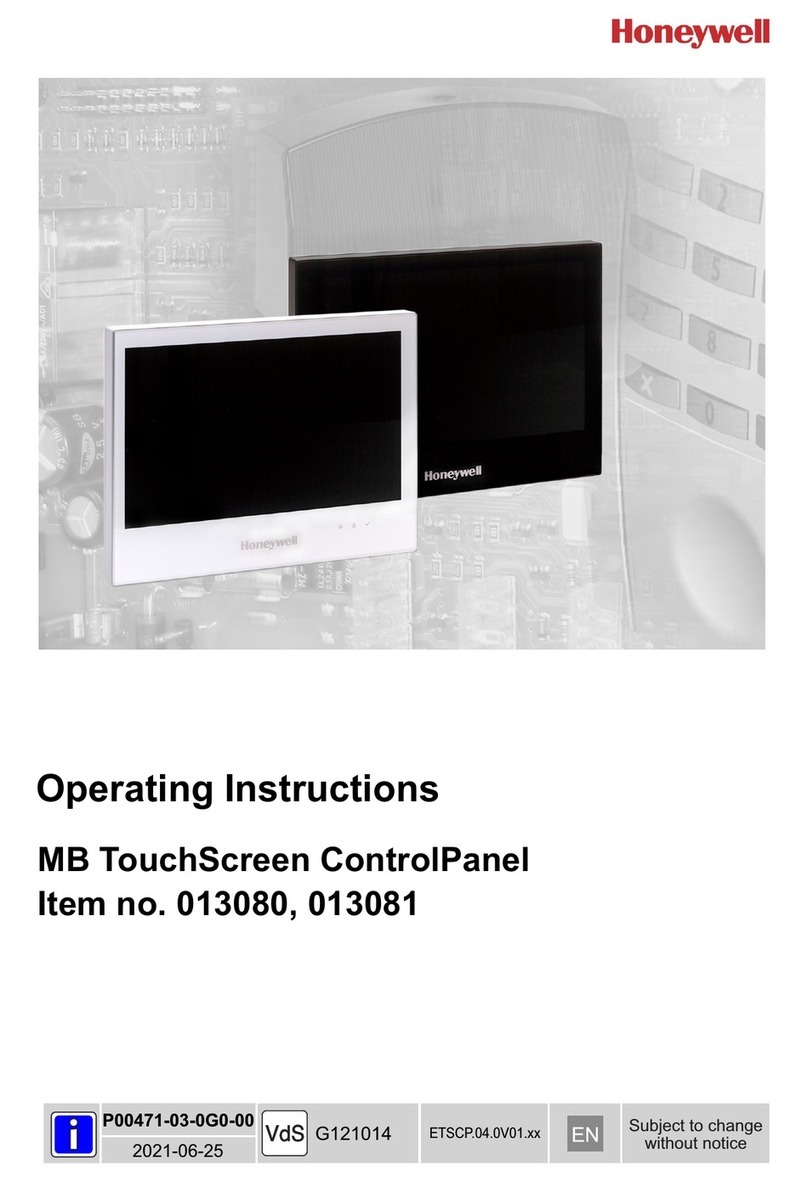
Honeywell Galaxy TouchCenter Plus User guide

800-18271 8/15 Rev. A1
Galaxy TouchCenter Plus
Installer Manual


Table of Contents
iii
About the System...........................................................................................................................5
Compatibility...................................................................................................................................................5
System Information .........................................................................................................................................5
Mounting.........................................................................................................................................................6
Wiring..............................................................................................................................................................7
Specifications ..................................................................................................................................................8
SD/SDHC Card Slot and Reset Button............................................................................................................8
Navigation Icons..............................................................................................................................................9
Panel Fault Displays........................................................................................................................................9
Initial Setup ...................................................................................................................................10
Initial Power Application ..............................................................................................................................10
IP Setup and Network Connections...............................................................................................................11
Setup..............................................................................................................................................13
Brightness and Volume Control ....................................................................................................................13
Display Setup ................................................................................................................................................13
Language Selection (if applicable)................................................................................................................13
Adjust the Screen Timeouts...........................................................................................................................14
Clean Screen..................................................................................................................................................14
Multi-Media....................................................................................................................................15
Video (Audio) Setup......................................................................................................................................15
Picture Setup..................................................................................................................................................16
Camera Setup ................................................................................................................................................17
System Setup................................................................................................................................19
Console Mode................................................................................................................................................19
Set RS485 Address........................................................................................................................................19
EN50131 Mode .............................................................................................................................................19
Screen Security..............................................................................................................................................20
Device Events................................................................................................................................................20
Control...........................................................................................................................................................20
User System Setup.......................................................................................................................21
How to Add a User........................................................................................................................................22
How to Delete a User ....................................................................................................................................22
How to Edit a User........................................................................................................................................23
Time/Date Setup............................................................................................................................................23
Setting Current Time and Date......................................................................................................................23
Setting Summer Time....................................................................................................................................24
Advanced Setup.............................................................................................................................................24
Keypad Test...................................................................................................................................................24
LCD Display Test..........................................................................................................................................24

Table of Contents (cont’d)
iv
Audio Test.....................................................................................................................................................25
LED Test .......................................................................................................................................................25
Calibration Test.............................................................................................................................................25
Keypad Reset.................................................................................................................................................26
Notes..............................................................................................................................................27

5
About the System
This guide provides information on how to install and configure Honeywell’s Galaxy TouchCenter Plus graphical
touch-screen keypads, which are Advanced User Interface (AUI) devices. Your system will comprise one of the
following keypads and the wall mount plastics:
CP045-00 Galaxy TouchCenter Plus flush mount
CP046-00 Galaxy TouchCenter Plus flush mount, with Prox
A045 Wall mount plastics for Galaxy TouchCenter Plus
Compatibility
The listing below identifies the alarm systems that the keypad can interface with, the maximum number of keypads that
can be used with each system, and the minimum alarm panel software revision level for compatibility.
Alarm system
Maximum number
of keypads
Minimum panel
software version
Flex/Flex+ 20
1
3.xx
Flex/Flex+ 50
1
3.xx
Flex/Flex+ 100
1
3.xx
Dimension 48
1
6.xx
Dimension 96
2
6.xx
Dimension 264
2
6.xx
Dimension 520
4
6.xx
Note: Only one Galaxy TouchCenter Plus keypad is permitted per RS485 line.
System Information
To view the current software/firmware version installed on your system, do the following:
ICON
ACTION
NOTES
1. On the Home screen, press the Setup icon, and
then enter an authorised code.
2. Press the System Info icon
The MAC Address, CRC, software version and
MCU firmware are also displayed.

About the System (cont’d)
6
Mounting
This keypad is for indoor use within the protected area only and should be mounted at a comfortable viewing level.
Avoid mounting in areas of high condensation such as bathrooms or in locations where bright light or sunlight shines
directly on the screen.
To mount the keypad:
1. Unclip the facia from the keypad to reveal four mounting screw holes.
2. If the customer has supplied an SD/SDHC media card containing videos and/or photos, fit the card in the slot in the
rear of the keypad as shown below.
3. Cut a hole in the wall 208 x 152 mm (ensure it is no larger than 214 x 158 mm). Ensure there is a depth from the
surface of the wall of at least 30 mm. If you need to attach the tamper to the wall to meet EN50131, ensure there is
no gap between the rear of the tamper and the wall using suitable packing material.
4. Make a hole in the back or sides of the recessed box and feed the RS485 cable through.
5. Place the recessed box in the hole and tighten the claw fasteners, which rotate 90 behind the plaster board. Continue
tightening until the box is securely held.
6. To meet EN50131, screw the tamper in the recessed box to the wall behind the box.
7. Go to Wiring (page 7) and complete the wiring.
8. Locate the keypad over the recessed box and ensure you can hear the tamper switch click, indicating that it is
closed. Ensure that the keypad sits flat against the recessed box without the need to apply excessive force. If the
keypad won’t sit flat against the recessed box or the
switch doesn’t click, adjust the tamper screw
(in to allow the keypad to locate and out
to ensure the switch closes).
9. Screw the keypad to the recessed box
using the four screws supplied.
10. Clip the facia in place.

About the System (cont’d)
7
Wiring
Connect the Galaxy TouchCenter Plus to the panel’s RS485 terminals. For maximum wire runs and wire sizes, refer to
your panel’s installation manual.
Connect the RS485 wires to the keypad terminal block as shown below.
The keypad draws up to 340mA at 9.6VDC, 260mA at 12VDC and 250mA at 13.8VDC.
If you power the keypad from your panel’s auxiliary power output, check your panel’s Installation and Setup
Guide and verify that this device and others do not exceed your panel's auxiliary power output capability. If it
does, use a supplementary power supply.

About the System (cont’d)
8
Specifications
Mechanical Specifications:
Width: 218 mm
Height: 162 mm
Depth: 34 mm
Weight: 629 g
Electrical Specifications:
9.6 VDC
12 VDC
13.8 VDC
Backlight OFF, Sound OFF, WIFI ON
170 mA
140 mA
130 mA
Backlight ON, Sound OFF, WIFI ON
280 mA
225 mA
200 mA
Backlight ON, Sound ON, WIFI ON
340 mA
260 mA
250 mA
Operating Environment: Humidity
93% RH, non-condensing
Temperature: Operating
−10˚C to 55˚C
Temperature: Shipping / Storage
−40˚C to 70˚C
ACE type
Type B (fixed equipment)
SD/SDHC Card Slot and Reset Button
The Galaxy TouchCenter Plus has a media card slot and reset button located behind the panel as shown below.
Note: If you need to insert a media card or access the reset button remember to do so before securing the keypad in
place.
Note: When EN50131 Mode* is enabled the system status line at the top of the keypad is not displayed.
*The EN50131 Display compliance feature is a European Standard designed to prevent unauthorized users from
viewing the status of the Security System.

About the System (cont’d)
9
Navigation Icons
To aid in the navigation through the Galaxy TouchCenter Plus screens a set of user-friendly icons has been provided.
The appearance and function are described below.
ICON
ICON TITLE
FUNCTION
Security
Accesses the Security screen
Control
Access the output control screen
Home
Return to the Home screen
Back
Return to the last screen viewed
Setup
Access the Setup menus
Picture
Allows a user to display personal photos in a slide show format
Minimise Home
Minimises the Home screen icons when viewing wallpaper displays
Maximise Home
Maximises the Home screen icons when viewing wallpaper displays
Panel Fault Displays
The Security screen displays an icon(s) if a panel fault(s) occurs. The following icons(s) may be shown as applicable to
your system:
ICON
MEANING
AC Loss –The system is not receiving AC power
Low Battery –The battery that powers the system during an AC power loss is low or an RF device has a
low battery
Comms Line Fail –The communications module has a line fail
Device Alarm –There is an alarm on the device shown
Zone Trouble –There is a zone fault
Tamper Alarm or Fault –There is a tamper alarm on the device shown or it is faulty

10
Initial Setup
Initial Power Application
When initially powered, the screen displays TouchCenter Plus and the loading progress indicator bar.
ACTION
NOTES
1. Apply power to the panel, which also powers
the Galaxy TouchCenter Plus. TouchCenter
Plus is displayed along with the loading
progress indicator bar. This is then followed by
the Set RS485 Address screen.
2. On the Set RS485 Address screen, do one of
the following:
a) Leave the default address unchanged (the
default address is 0).
b) Use the up/down arrows to select a new
address if 0 is used by another device on the
panel.
3. Press OK.
4. On the next screen, select the required language
and, if not required, deselect EN50131 Mode (it
is selected by default).
5. Click OK. The Home screen is displayed.
6. To set the time and date refer to Time/Date
Setup.
Note: The Galaxy TouchCenter Plus has been calibrated at
the factory. If the screen requires recalibration, the end user
may do so via the Keypad Test screen. See the LCD
Display Test section for instructions.

Initial Setup (cont’d)
11
IP Setup and Network Connections
IP Address Setup
In most cases, IP addresses are assigned automatically (the Obtain address auto setting). However, you may require a
static (fixed) IP address that can be found by accessing your router. Refer to your router instructions.
Setup a LAN Connection
On the IP Setup screen, add a LAN network connection as follows:
ICON
ACTION
NOTES
1. Connect an Ethernet cable between the
router and the keypad and setup any video
cameras.
2. On the Home screen, press the Setup icon,
and then enter an authorised code.
3. Press the IP Setup icon.
4. Press the LAN ON button.
5. Press the Save icon: the IP information is
automatically updated.
6. Return to the IP Setup screen. Check that
the information is displayed.
7. If the IP address is not displayed, change the
Internet Connection type to Static, and
then manually enter the necessary IP
information from your router. Press the
Save icon; the IP information is
automatically updated.
A pop-up window displays:
This will switch off WLAN Network, do you want
to continue? Yes or No

Initial Setup (cont’d)
12
Setup a WIFI (WLAN) Connection
On the IP Setup screen, add a WIFI network connection as follows:
ICON
ACTION
NOTES
1. On the Home screen, press the Setup icon,
and then enter an authorised code.
2. Press the IP Setup icon.
3. Press the WIFI ON button.
4. Do one of the following:
a) Use the scroll bar to locate a network
from the list of WiFi Networks to connect
to and highlight that field. If your router
is not listed press the Refresh icon.
b) If your router is not listed, even after
refreshing the list, scroll to the bottom of
the list and select Add Network.
Highlight each field to enter the required
information for SSID, Security Mode, and
Passphrase / Shared Key on the Data
Entry Keyboard and press GO.
5. Press the Save icon. Pressing Save when
changing the port number resets the keypad.
A pop-up window displays:
This will switch off LAN Network, do you want to
continue? Yes or No.
Use the Data Entry Keyboard to enter the required
information.
Press the up arrow key to switch to capital
letters.
Press the Space key to add a space between
characters.
Press the xkey to delete/backspace.
Press the ABC/.?123/Åå key to switch between
numerals and symbols/characters.
A pop-up window displays:
Success
WIFI Network Saved

13
Setup
This section describes how to use the brightness and volume controls, and how to select the language and adjust the
screen timeouts.
Brightness and Volume Control
To set the brightness and volume:
ICON
ACTION
NOTES
1. On the Home screen, press the Setup icon, and
then enter an authorised code.
2. Move the Brightness and/or Volume slide bars up
or down to increase or decrease the settings.
3. Press the Save icon.
If changes are made, when you exit a pop-up
window displays:
Information
Settings saved
Display Setup
On the Display Setup screen you can access Language, Backlight Off After, To Homepage After, Auto Slideshow
After, and Clean Screen.
Language Selection (if applicable)
The Galaxy TouchCenter Plus can display ten different languages.
To change the language:
ICON
ACTION
NOTES
1. On the Home screen, press the Setup icon, and
then enter an authorised code.
2. Press the Display Setup icon.
3. Press the Language button and then, using the
up/down arrow buttons, select a language.
4. Press the Save icon.
5. Press OK.
After step 4, the following message is
displayed:
Information
Language has been changed
Press OK or Cancel

Setup (cont’d)
14
Adjust the Screen Timeouts
When the keypad is left idle, it automatically:
Turns the backlight off after the selected backlight off time has expired (unless the Never option is selected).
Returns to the Home screen after the selected To Homepage After time has expired (unless Never option is
selected), and
If enabled, the Auto Slideshow After time begins the slide show.
Note: In EN50131 Mode you can only adjust the backlight off after time.
To select the desired screen timeouts:
ICON
ACTION
NOTES
1. On the Home screen, press the Setup icon, and
then enter an authorised code.
2. Press the Display Setup icon.
3. Press the desired timeout button.
4. Use the up/down arrow buttons to change the
timeout.
5. Press the Save icon.
Settings include:
Backlight Off After time
Return To Homepage After time
Auto Slideshow After time
Clean Screen
With the exception of normal cleaning, the keypad is maintenance free.
Press the Display Setup icon, and do the following:
ICON
ACTION
NOTES
1. Press the Clean Screen icon. A popup window
displays Touch Screen has been disabled so that
you may wipe the screen clean. Please use a
damp, soft cloth. DO NOT use any liquids,
sprays, or ammonia-based cleansers. Press
CONTINUE to disable touchscreen.
2. Press Continue, and then wipe the screen.
When the Continue icon is pressed the
message Touch Screen Disabled for =30
Seconds is displayed. During these 30
seconds the touch screen should be wiped
clean of fingerprints using a mild soap solution
and a soft cloth. When the counter reaches
zero, the window automatically closes and the
touch screen is active.
IMPORTANT: Do not use an abrasive cleaning agent or abrasive cloth when cleaning the keypad or damage to the
touch screen may occur.

15
Multi-Media
The multi-media options allow you to display personal photos in a slide show format and video (audio) files.
Important: The feature will only work if you fitted a personal media (SD/SDHC) card with stored photos and /or video
(audio) files prior to installing the keypad.
Video (Audio) Setup
This feature allows you to display videos and can be accessed from the Home screen by pressing the Multimedia icon.
To access this function:
ICON
ACTION
NOTES
1. Press the Multimedia icon.
2. Press the Video icon.
3. Highlight a video file from the list and press the
Play icon to start the selected video.
4. Press the Repeat icon to continually replay the
selected video.
5. Deselect the Repeat icon to automatically play the
complete list of video files starting with the first
video and ending with the last.
A video converter is required to convert videos
for proper playback on the TouchCenter Plus
keypad. Use an Internet search engine to locate
and download a video converter, then follow the
steps in the video converter instructions
(provided in the carton).
Note: Maximum video resolution must not
exceed 400 x 240.
Video Icons
Use the slide bar to scroll through the video list.
Press the appropriate icon to control the video:
Play, Pause, Full View, Stop or Repeat.
To exit Full View mode at any time while a video
is playing, press anywhere on the screen.
Play
Pause
Full View
Repeat
Stop

Multi-Media (cont’d)
16
Picture Setup
This feature allows the user to display up to 1000 personal photos on the touch screen and can be accessed from the
Home screen by pressing the Multimedia icon. To access this function:
ICON
ACTION
NOTES
1. Press the Multimedia icon.
2. Press the Picture icon.
3. Press the Transition dropdown to select the type
of viewing transition (Standard, Horizontal,
Vertical or Fade Out).
4. Press the Slide Delay dropdown to select the time
interval that you want to allow between each
photo being viewed. Choose from (5, 10, 15, or 20
seconds).
5. Add and remove images from the slide show as
follows:
a) To remove all images to the slide show, press
Clear All.
b) To add selected images to the slide show,
highlight each image in the list or use the
Previous Image or Next Image icons to
display the image, and then press the Add
Image icon.
c) To remove an image from the slide show,
highlight the image or use the Previous Image
or Next Image icons to display the image, and
then press the Deselect Image icon.
To set a picture as wallpaper:
1. Use the slide bar to highlight the file you want to
be displayed on the keypad screen.
2. Press the Set Wallpaper icon, and then view your
selection on the Home screen.
Photo files can be viewed from the (SD/SDHC)
Card. Formats supported are .bmp, png or .jpg
files.
If no images are added to a slide show then all
images are shown by default.
Notes:
To exit slide show at any time and resume
keypad operation, press anywhere on the
screen.
The first image is displayed and a list of
stored images appears on the screen.
When an image is loading, no other picture
setup function can be performed (play,
previous, next, add or set wallpaper).
Press the TOP button to move up one level in
the directory.
Press the OPEN button to view larger images
and/or open directories, select from the list of
stored images.
Press the CLEAR ALL button to clear all
selected pictures from the current slide show
rotation. The slide show reverts to showing all
images.
Note: On the Home screen press the Minimize
Home icon to reduce the Home screen icons
and to have better visibility of the wallpaper.
Press the Maximize Home icon to maximize the
Home screen icons.
Picture Icons
Home Screen Icons
Play Image
Previous
Image
Next Image
Add Image
Deselect
Image
Set
Wallpaper
Minimize
Home
Maximize
Home

Multi-Media (cont’d)
17
Camera Setup
The Camera feature allows you to enrol cameras and view up to eight cameras at one time. If using existing (mounted)
cameras, go to Step 4 below. If this is a first time setup, you will need to Discover/Configure the cameras prior to
mounting and then follow the steps below.
The following cameras were tested and are supported:
Performance Series:
HED1PR3, HED3PR3, H4D3PRV3, H4D3PRV2, HBD1PR1, HBD3PR1, HBD3PR2
EquIP Series S:
HCW2S2X, H3D2S2X, H4D2S2X, H3D2SR2X, HCD2S2X, H3D3S2X, H4D3S2X, H3D3SR2X,
HCD5S2X, H3D5S2X, H4D5S2X, H3D5SR2X, H2S1P6X, H2S2P6X
HBD2PR1X, H2D2PR1X and HVD3V8MPD (lense)
The cameras should be setup using the appropriate, dedicated configuration tool supplied with the camera prior to the
importing camera to the TouchCenter Plus. The settings should not exceed below values.
Maximum acceptable resolution for the cameras is CIF (352x288), in case of EquIP Series S it is acceptable to use
640x480
Maximum acceptable frame rate is 5
Encoding should be set to H.264 or MJPEG (however H.264 delivers better image quality)
If you want to be able to use the other camera channels for recording etc. it is advised to use the second or last
available channel in the camera for the TouchCenter Plus

Multi-Media (cont’d)
18
ICON
ACTION
NOTES
1. Connect a Cat5/6 cable to your camera (LAN) and
connect the opposite end to an Ethernet connection
on your router.
2. Apply power to the Camera. It may take a few
seconds for initial power-up of camera.
3. Apply appropriate settings to the camera by
dedicated camera tool
4. On the Home screen press the Camera icon and an
authorized code (or press the Multimedia icon
followed by the Camera icon. The Camera List
screen is displayed.
5. Press the Discover icon to locate the camera.
6. If the camera information is not automatically
obtained please check the settings from point 3 and
press Discover again.
Setup Icons
Camera Icons
Discover
Add
Edit
Delete
Delete
All
Settings
Camera
Wifi
Play
Auto
Pan
Quad
View
Full
View
Pan/Tilt
Back
Notes:
To use the Pan/Tilt feature, select the camera name from the camera list and then press Pan/Tilt.

19
System Setup
This section describes how to change system settings.
Console Mode
Console Mode displays an alpha/numeric keypad on the screen that can be used to make changes on the panel.
To access the Console Mode:
ICON
ACTION
NOTES
On the Home screen, press the Console Mode
icon, and then enter an authorised code.
Set RS485 Address
Follow this procedure if you want to change the keypad’s RS485 address in the panel.
ICON
ACTION
NOTES
1. On the Home screen, press the Setup icon, and
then enter an authorised engineer code.
2. Press the System Setup icon.
3. Press the Eng. Setup icon.
4. Press the RS485 Address icon.
5. Use the up/down arrows to select a valid
address.
6. Press the Apply icon.
EN50131 Mode
The EN50131 compliance feature is part of a European Standard designed to prevent unauthorized users from viewing
the status of the security system. When EN50131 Mode is turned on the status bar is not displayed on the Home screen.
Follow this procedure if you want to enable/disable EN50131 Mode:
ICON
ACTION
NOTES
1. On the Home screen, press the Setup icon, and
then enter an authorised engineer code.
2. Press the System Setup icon.
3. Press the Eng. Setup icon.
4. Press the Options icon.
5. Select/deselect EN50131 Mode.
6. Press the Apply icon.

System Setup (cont’d)
20
Screen Security
The Screen Security screen displays a list of keypad information and setup screens and the authority levels assigned to
each. To view and/or edit the authority levels, do the following:
ICON
ACTION
NOTES
1. On the Home screen, press the Setup icon, and
then enter an authorised engineer code.
2. Press the System Setup icon.
3. Press the Eng. Setup icon.
4. Press the Screen Security icon.
5. If changes are necessary, select the line to be
changed and a new authority level, and then
press Apply.
6. Press the Apply icon.
Device Events
Option not available
Control
The TouchCenter Plus can be used to control building systems such as lighting, air conditioning and gates.
To setup control, if required:
ICON
ACTION
NOTES
1. In the panel, use option 53.XXXX.6 (refer to the
panel’s Installer Manual) to setup the
devices/systems that will be controlled from the
keypad.
2. On the keypad, press the Control icon.
You will see a switch icon for each device/system
that can be controlled from the keypad. A lightbulb
symbol may be displayed next to a switch if Show
Status has been enabled in the panel. The
lightbulb symbol changes to lit when the switch
icon is pressed.
Other manuals for Galaxy TouchCenter Plus
2
Table of contents
Other Honeywell Touchscreen manuals