manuals.online logo
Brands
  1. Home
  2. •
  3. Brands
  4. •
  5. Hontzsch
  6. •
  7. Measuring Instrument
  8. •
  9. Hontzsch TA20 Operation manual

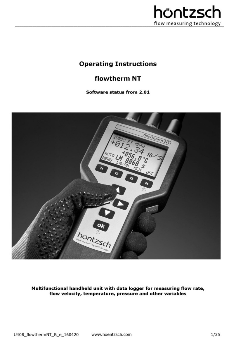
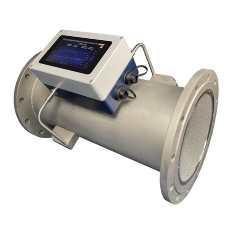
Hontzsch TA20 Operation manual

User’s Information TA Probes
Probe alignment
Thermal flow sensors TA are to be
aligned in the direction of flow.
•
•
•
•
U204_TA20_B_e_040527
References to danger
Probe in pressurized pipeline:
- insertion or retraction of probe in
depressurized conditions only!
- In the case of probe guide pieces
with probe attachment
by TEFLON
clamping bush:
increase the tension on the
clamping bush from time to time
(TEFLON runs causing the
clamping fixture to lose initial
gripping power)
Probe with probe guide piece: after
positioning a probe in the pipeline
fix the probe tube!
•
•
Fitting instructions
The probes should be so fitted that
flow is according to the flow direc-
tion provided for.
Alignment estimated by sight does
not interfere with the measurement.
Rather more deviations from the
nominal position can however af-
fect the measurement.
In the case of probes with connec-
tion housing the screwed cable
gland on the connection housing is
to be aligned to the direction of
flow.
In the case of probes without con-
nection housing an adjustable ‘di-
rection indicator’ can be used to
determine the sensor flow direction
and insertion depth.
they are fitted vibration-free and
not in the immediate vicinity of
electromagnetic or thermal sources
of interference. The T95 response
time of all TA sensors of air veloci-
ties of around 5 Nm/s is approx.
10 s. The response time decreases
at higher velocities. Changes in the
medium temperature result in an
exact measured value only then,
when the surroundings of the TA
sensor are again in thermal equilib-
rium.
the probe mounting device does
not affect the flow if possible.
no drops hit the sensor. A moisten-
ing of the sensor with non-drip oil
does not affect the measurement.
Probe fitting position
The probe fitting position of TA10
sensors can be chosen at random.
TA20 sensors should not be fitted
vertically from above ±30° in a
pipeline for avoidance of measured
convective flow at zero flow.
In the case of the TA20 flow sen-
sors, in supply since around 1/98,
no requirements regarding the fit-
ting position for avoidance of
measured convective flow at zero
flow to be heeded.
1of 4
Ò
no no no
Supplementary to this User’s Infor-
mation we refer to the correspond-
ing Technical Data Sheet with the
specific data relating to your order
and details of the Manual as well
as to Data Sheets Thermal Flow
Sensors TA and Flow Velocity
Calibration TA.The data in these
documents supplements the follow-
ing User’s Information.
Flow direction TA20 Flow direction TA10
Version ‘98
CaTeCCaTeC
'0174 272330 70174 272340
*[email protected]
www.catec.nl
2of 4
Greater measurement cross
sections
To determine the average flow ve-
locity vmin greater measurement
cross sections a preliminary ex-
amination is to be carried out to
determine the flow profile/
measurement cross section
topography. As a result of this
study an optimum measuring
point is to be fixed and the
associated coefficient for the
conversion of the local velocity vpto
the average velocity vmto be stipu-
lated.
For further information see for
example
U204_TA20_B_e_040527
upstream downstream
15·Di 5·Di
reduction
enlargement
18·Di 5·Di
90° elbow
or T-form pipe
20·Di 5·Di
2·90° elbow
25·Di 5·Di
2·90° elbow
3-dimensional
40·Di 5·Di
with flow
straightener
8·Di 5·Di
TA sensor
ð
v
Calibration number KKZ
The calibration number KKZ de-
scribes the course of a calibration
curve. It is the basis for the
linearization of a TA sensor char-
acteristic. The KKZ is individually
determined for each sensor and
must be deposited at the appropri-
ate evaluation unit:
•
•
in the case of a transducer without
keypad and display please make
sure that the KKZ shown on the
transducer is the same as the KKZ
of the connected sensor.
in the case of an evaluation unit
with keypad and display: check the
effective parameter settings by us-
ing the èkey (inquiry mode) and if
necessary enter KKZ appertaining
to the sensor via the keypad.
•
•
Data Sheet TA, ‘Coefficient /
Profilfe factor’
•
Result report of the Hessian State
Institute for the Environment, ‘Envi-
ronmental Planning, Protection of
Labour and Environmental Protec-
tion Pamphlet 167’: Überprüfung
der Repräsentativität von
Meßpunkten bei der Ermittlung der
Emissionen luftfremder Stoffe
unter Anwendung von
Meßquerschnitts-topographien,
VDI/VDE 2640-3 ‘Measurement of
gas flow... Velocity area method’
Input/output sections
When measuring in a measure-
ment section of inside diameter Di
it must be observed that optimal
accuracy when converting the local
velocity vptothe average velocity
vmvm= vp·PF
(PF, CF = Profile Factor,
Coefficient)
is only guaranteed
when
input/output sided irrotational flow
prevails and moreover
sufficient straight, unhindered
input section as well as sufficient
straight, unhindered output
section is available.
The illustrations show the recom-
mended minimum pipe length,
given as a multiple of Di. The use
of greater lengths is always advis-
able.
Should a suitably long, straight
section line not be available then
the measurement cross section is
to be so placed that 2/3 of the
straight pipe section are upstream
and 1/3 downstream of the meas-
urement cross section.
•
•
Standard designs of flow straight-
eners, see for example DIN ISO
5167-1 ‘Measurement of fluid flow
by means of pressure differential
devices’
3of 4
Cleaning the sensor
Inapplications where dirt can
settle on the sensor, thermal flow
sensors should be cleaned at
regular intervals. Start by checking
the necessity for cleaning at short
intervals by visible inspection in
order to establish an optimal
cleaning interval.
Soiled measuring probes can be
cleaned with a paint brush or
small rag using a cleaning agent
which does not leave residue
when dry. Cleaning liquid must on
no account be allowed to
penetrate measuring probes
which are not tight; just dampen
rag or brush. When choosing the
cleaning agent pay attention to the
compatibility with the sensor
materials.
Connection line
For the connection between
sensor and evaluation unit - in the
case of shorter lines with no elec-
tromagnetic interference - a line
with simple copper shielded braid
can be used: LiYCY. In the case of
longer lines or lines with severe
electromagnetic interference a
double-shielded line only is to be
used: LiYCY-CY. Number of wires
and cross section in mm2for each
wire: 8·0.50. Maximum conductor
resistance for each wire: 10 W.
Resistances for fine-strand wires
according to VDE 0295 / IEC 228:
79 W/km with wire cross section
0.25 mm2,
39 W/km with wire cross section
0.50 mm2,
26 W/km with wire cross section
0.75 mm2
Circuit diagram
TA sensor with evaluation unit only
to be connected according to ap-
propriate circuit diagram.
EMC information
for installation in facilities with
interference emitting components:
U204_TA20_B_e_040527
Connection recommendation for a TA sensor with shorter lines with no
electromagnetic interference
TA sensor
RF-shielded housing evaluation unit
2...4 m
x m
Connection recommendation for a TA sensor with longer lines or lines with
severe electromagnetic interference
TA sensor 2...4 m
RF-shielded housing
x m
evaluation unit
Lay the shielding from analog
signal lines only on one side - if
possible at the evaluation unit - and
of low impedance. Twist non-
shielded lines: is effective against
balanced interference to source
terminals.
•
•
•
Lay shieldings from digital signal
lines on both sides over a large
area. In the case of potential differ-
ences between these points: lay
separate potential equalization
lines.
For connections on connection ca-
ble points of separation use pre-
ferred shielded plug connector.
When using terminals: place termi-
nals in an RF-shielded housing
and use EMC-correct cable lead-
ins. Contact outer shielding of the
connecting line to the cable lead-
ins.
All lines to be kept short! Loops in
the line can destroy protective
measures. Lay non-reserved wires
in a cable on both sides on earthed
wire potential. Lay cables and
wires close to the reference
potential, for instance side panels,
mounting plates or steel girders.
•
•Spacial separation of lines
emitting interference from
measuring cables and evaluation
•
•
•
•When using frequency converters
the influence of RF interference
emittance must be taken into con-
sideration from the outset and in-
creased active and passive anti-
interference measures must be
taken: Decouple the mains input
of the frequency converter by
means of a spark filter against
active interference emittances. In
addition this increases the
Special attention should be di-
rected to the motor wire. The
motor wire between converter and
motor should be shielded, the
Metallic parts in the service
cabinet - as for instance sub-rack
with control electronics or
mounting plates - very good large
area and RF-like conductive
Relays, contactors, electro valves
installed in the same circuit to be
wired by means of spark arrester
combinations or excess-voltage
alarge area and of low
impedance at sensor and
In the case of lines over 30 m or
lines with severe electromagnetic
interference - lines between
sensor and evaluation unit - the
use of a double-shielded line is
recommended: lay inner shield on
one side of the evaluation unit, lay
outer shield on both sides cover-
ing
•
4of 4
Höntzsch GmbH
P.O. Box 1324 D-71303 Waiblingen
Robert-Bosch-Str. 8
D-71334 Waiblingen (Hegnach)
Telephone 07151/1716-0
Facsimile 07151/58402
Subject to alteration
U204_TA20_B_e_040527
Measured value too high:
sensor is placed not far enough
downstream from a cooling instal-
lation
coefficient set too high
coefficient too high for the meas-
uring position. See ‘Greater Meas-
urement Cross Sections’: Flow
profile other than expected, e.g.
caused by subsequent structural
alterations to the measurement
section. Please note: the flow pro-
file can change dependent on ve-
locity when the input/output sec-
tions are too short.
volumetric display: pipe inside di-
ameter Di setting too great
effective electromagnetic interfer-
ences
wrong KKZ
measuring gas other than air
Measured value fluctuates:
time constant set at too low a
value
expected measured value fluctua-
tion does not correspond to the
real measured value fluctuation
effective electromagnetic interfer-
ences
•
•
•
•
•
•
•
•
•
•
Maintenance
In applications where dirt can
settle on the sensor, sensor
should be cleaned at regular
intervals!
Service
Please contact Höntzsch GmbH
Corrective maintenance
to be carried out by Höntzsch
GmbH. Please enclose a descrip-
tion of errors when returning faulty
instruments. If the instruments
have been used in hazardous ma-
terials please inform us of any
safety precautions to be taken dur-
ing corrective maintenance. We
see it as a conscientious duty to
our staff to request you to furnish
us with this information.
Causes of trouble
no measured value:
coefficient set at 0.000
sensor not connected
(display EEEE or FFFF)
parting of connection cable or
short in the connection cable
(display EEEE or FFFF)
measured value too low:
sensor is placed not far enough
downstream from a heating instal-
lation
coefficient set too low
coefficient too low for the measur-
ing position. See ‘Greater Meas-
urement Cross Sections’: Flow
profile other than expected, e.g.
caused by subsequent structural
alterations to the measurement
section.
Please note: the flow profile can
change dependent on velocity
when the input/output sections are
too short.
volumetric display: pipe inside di-
ameter Di setting too small
rotational flow with centric posi-
tioning of the sensor
sensor not optimumly aligned to
the flow. Example: TA20 sensor fit-
ted twisted by 30°: measured val-
ues by v > 5 Nm/s about approx.
10% too small.
reduced thermal coupling in the
sensor element as a result of
strong vibration or impact (for in-
stance sensor has been
dropped).
sensor soiled: results in reduced
thermal coupling
effective electromagnetic interfer-
ences
burden at current output greater
than permissible according to
Technichal Data Sheet. Effect: cor-
rect output values in a lower part
of the measuring range, no longer
increasing output values in an
upper part of the measuring
range.
setting of the scaling for the
analog output not as expected
wrong KKZ
measuring gas other than air
•
•
•
•
•
•
•
•
•
•
•
•
•
•
•
•
other errors
all parameters altered: effective
electromagnetic interferences.
Unlike incorrect parameter
settings by the user,
electromagnetic interference
usually results in parameter
settings which cannot be effected
by operating error. In the case of
an evaluation unit with keypad and
display: use the èkey for param-
eter inquiry. This inquiry mode
does not change the settings.
expected measured value
fluctation does not correspond to
the real measured value fluctua-
tion: time constant set too high
•
•

This manual suits for next models

1

Other Hontzsch Measuring Instrument manuals

Hontzsch ExactSonic P User manual

Hontzsch

Hontzsch ExactSonic P User manual

Hontzsch flowtherm NT User manual

Hontzsch

Hontzsch flowtherm NT User manual

Hontzsch ExactSonic III User manual

Hontzsch

Hontzsch ExactSonic III User manual

Hontzsch flowtherm Ex User manual

Hontzsch

Hontzsch flowtherm Ex User manual

Popular Measuring Instrument manuals by other brands

Humboldt FD-4A product manual

Humboldt

Humboldt FD-4A product manual

London Electronics Fusion-L 6 digit Connection details, scaling and general information

London Electronics

London Electronics Fusion-L 6 digit Connection details, scaling and general information

Hoyt NA5 user guide

Hoyt

Hoyt NA5 user guide

ANALOX Ax60+ Multi-Gas quick start guide

ANALOX

ANALOX Ax60+ Multi-Gas quick start guide

Zeiss MEL 80 manual

Zeiss

Zeiss MEL 80 manual

Vynco VMC51 quick start guide

Vynco

Vynco VMC51 quick start guide

Mecmesin Compact Force Gauge operating manual

Mecmesin

Mecmesin Compact Force Gauge operating manual

GE CheckPoint Quick setup guide

GE

GE CheckPoint Quick setup guide

Water I.D. PoolLAB 1.0 user manual

Water I.D.

Water I.D. PoolLAB 1.0 user manual

horiba HP-200 instruction manual

horiba

horiba HP-200 instruction manual

Teletek electronics SR-300B Operation manual

Teletek electronics

Teletek electronics SR-300B Operation manual

Teledyne Lecroy WaveMaster 8000HD Getting started guide

Teledyne Lecroy

Teledyne Lecroy WaveMaster 8000HD Getting started guide

ISTEC 1820 installation instructions

ISTEC

ISTEC 1820 installation instructions

ZHYQ GND15 quick start guide

ZHYQ

ZHYQ GND15 quick start guide

PCB Piezotronics IMI SENSORS HT625B01 Installation and operating manual

PCB Piezotronics

PCB Piezotronics IMI SENSORS HT625B01 Installation and operating manual

GEONiN DM-100 manual

GEONiN

GEONiN DM-100 manual

MyTek DDD-603 Reference manual

MyTek

MyTek DDD-603 Reference manual

ROLEC SmartCard ACEU0160 Operation manual

ROLEC

ROLEC SmartCard ACEU0160 Operation manual

manuals.online logo
manuals.online logoBrands
  • About & Mission
  • Contact us
  • Privacy Policy
  • Terms and Conditions

Copyright 2025 Manuals.Online. All Rights Reserved.