__________________________________________________________________________________________________
___________________________________________________________________________________________________
U398_UVATP_B_e_190425 5/17
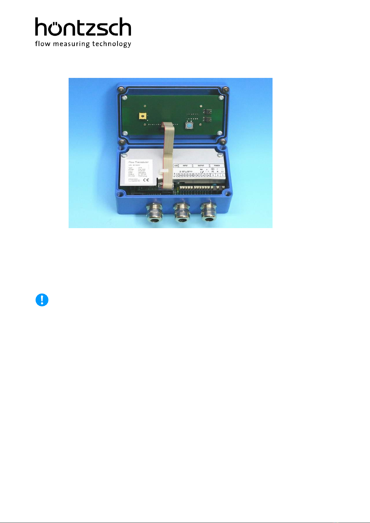
5.4 Housing and Connectors
Protection class : IP65
Material : aluminium
External dimensions : L/W/H = 150/100/80 mm
Cable entry point : nickel-plated brass screwed cable glands
for cable diameter 5 ... 10 mm
with cable shielding connections
Connections : 'push in' PCB terminals
for wire cross-section 0.14 ... 1.5 mm²
No tools necessary for core connection –simply insert strands
(twisted or with end sleeve) into the terminal.
To separate strands apply pressure to the terminal release spring using
a pen or screwdriver.
5.5 Electrical Data
Supply voltage:
24 V DC (20 ... 27 V DC), power < 5 W
alternatively:
12 V DC (10 ... 17 V DC), power < 5 W
The mains supply is electrically isolated from the UVATP inputs and outputs.
Input flow v/VA: (separate transducers only)
for Höntzsch vortex flow sensors VA as measuring tube (VA Di ...),
resolution 0.125 Hz.
Input temperature T:
for Pt100 temperature probe in 4-wire system,
acquisition time constant 2 s,
resolution 0.1 K.
Input pressure P:
for absolute pressure sensors 4 .. 20 mA, 12 .. 36 V in 2-wire system,
acquisition time constant 0.125 s,
resolution 1 hPa,
initial and terminal values configurable.
Analog outputs A1 and A2:
optionally, the analog outputs can be electrically isolated with each other and from the inputs using an
additional isolating amplifier.
Analog output A1 precision:
high precision analog output,
update every 0.125 s,
time constant 4 s, with frequency hopping > 25 % 2 s,
time constants up to 99 s are configurable.
4 ... 20 mA = 0 ... x kg/h, (NV/t)
terminal value x configurable / resistance max. 500 Ohm,
alternatively:
0 ... 10 V = 0 ... x kg/h, (NV/t)
terminal value x configurable / impedance 1 kOhm