Hontzsch UVA User manual

__________________________________________________________________________________________________
______________________________________________________________________________________
U327_UFAUVALDG16_B_e_170808 www.hoentzsch.com 1/15
Transducers UFA and UVA
in LDG16 housing
Operating Instructions
Vane wheel flow sensors FA
Vortex flow sensors VA

________________________________________________________________________________________
______________________________________________________________________________________
2/15 www.hoentzsch.com U327_UFAUVALDG16_B_e_170808
Contents
1
Safety Symbols
2
Application according to Regulations
3
Operating Safety
4
Scope of Delivery
4.1
Description, Type Plates
5
Technical Specifications
5.1
Conformity with Standards
5.2
Storage Conditions
5.3
Operating Conditions
5.4
Compatibility
5.5
Housing and Connectors
5.6
Electrical Data
5.7
Measurement Uncertainty
6
Installation
6.1
Block Diagram
6.2
Wiring Diagrams
6.2.1
Power supply
6.2.2
Sensor input
6.2.3
Analog output
6.2.4
Relay output
6.2.5
Interface RS232
6.3
Tips on Electromagnetic Compatibility (EMC)
6.4
Connecting Cable
7
Functional Description
8
Settings
9
Performance Test
10
Initial Operation
11
Operation
12
Shut-down, Dismantling
13
Inspection
14
Maintenance
15
Calibration
16
Troubleshooting
17
Returns
18
Disposal
19
Replacement Parts
20
Declaration of Conformity, Manufacturer’s Declaration

__________________________________________________________________________________________________
______________________________________________________________________________________
U327_UFAUVALDG16_B_e_170808 www.hoentzsch.com 3/15
1 Safety Symbols
Warning!
Failure to observe the instructions can result in serious injury and damage to property!
Important notice!
Non-observance can result in serious damage to the equipment or restriction in performance!
2 Application according to Regulations
Transducers UFA and UVA are instruments for measuring flow velocity and flow rate:
UFA for use with vane wheel flow sensors FA or FAR and measuring tubes FA Di or FAR Di and UVA for use
with vortex flow sensors VA40 and measuring tubes VA Di. These instruments are designed for industrial
application. The LDG16 is a mounting rail housing in protection class IP20 designed primarily for use in
control cabinets.
The manufacturer is not liable for damage caused by improper use and/or non-compliance with the regula-
tions.
Do not carry out any structural modifications to the transducers.
Always follow the instructions on the type plate, especially the information regarding supply voltage.
3 Operating Safety
All steps described below must be carried out by qualified personnel only!
Please read the Operating Instructions carefully before unpacking the equipment!
Safety can only be guaranteed if the equipment is operated in accordance with the regulations. Improper
handling can result in serious injury and damage to property.
4 Scope of Delivery
- Transducer UFA or UVA for mounting rail assembly
- Operating Instructions, Data Sheet
- CD-ROM with PC configuration software UCOM (optional)
- Interface cable RS232 for PC COM port connection (optional)
- USB adapter in addition to the interface cable RS232 (optional)
Please check that everything listed in the Delivery Note / Technical Data Sheet is included in the delivery.

________________________________________________________________________________________
______________________________________________________________________________________
4/15 www.hoentzsch.com U327_UFAUVALDG16_B_e_170808
4.1 Description, Type Plates
One of the following type plates can be found on the side of the housing:
Type plate UFA Type plate UVA
Type: UFA : transducer for vane wheel sensors
UVA : transducer for vortex sensors
S/N.: : serial number
Power: 230 VAC : supply voltage 230 V AC voltage
24 VDC : supply voltage 24 V DC voltage
12 VDC : supply voltage 12 V DC voltage
Input: FA/FAR : input for vane wheel sensors FA or FAR
VA : input for vortex sensors
Filter: ... : filtration of vane wheel input frequency
Output: 4-20 mA : analog output current 4-20 mA
0-10 V : analog output voltage 0-10V
RS232: ... : behind the front cover
5 Technical Specifications
5.1 Conformity with Standards
Transducers UFA / UVA are manufactured according to the best available technology, are safe and reliable
and comply with the relevant regulations, EU directives and standards.
5.2 Storage Conditions
Storage temperature: -30 to +70 °C

__________________________________________________________________________________________________
______________________________________________________________________________________
U327_UFAUVALDG16_B_e_170808 www.hoentzsch.com 5/15
5.3 Operating Conditions
ambient air temperature in use : 0 to +50 °C
place of installation : control cabinet on mounting rail EN 50022
protection class : IP20
mounting attitude : no restrictions
5.4 Compatibility
All Höntzsch vane wheel probes FA or FAR and all Höntzsch vane wheel measuring tubes FA Di or FAR Di
(without integrated transducer) can be connected to the UFA transducer.
The UFA replaces the U2a transducer with FA / FAR input.
All Höntzsch vortex probes VA and all Höntzsch vortex measuring tubes VA Di (without integrated trans-
ducer) can be connected to the UVA transducer. The UVA replaces the U2a transducer with VA input.
5.5 Housing and Connectors
The LDG16 housing is designed for snapping on to 35mm DIN rail according to DIN EN 60715 and SN EN
50022 or for screwed connection. It is an insulator housing complying with machine and automobile indu-
stry regulations with 16 shock-proof terminals according to DIN VDE 0100 and VGB4, for wires with cross-
section 0.14 ... 4 mm².
Protection class : housing IP40, terminals IP20
Material : Macrolon
connections : by terminals
external dimensions : W/H/D = 55/75/110 mm
5.6 Electrical Data
Supply voltage, mains supply:
230 V AC (215 ... 255 V AC), 50 ... 60 Hz, power < 10 VA
24 V DC (20 ... 27 V DC), power < 5 W
12 V DC (10 ... 17 V DC), power < 5 W
The mains supply is electrically isolated from the UFA/UVA inputs and outputs.
UFA input flow v/FA or v/FAR:
for Höntzsch vane wheel flow sensors FA and FAR designed as probes (ZS, TS ..., ZSR, TSR ...) and as
measuring tubes (FA Di, FAR Di ...).
When using sensors in Ex-zone category 2 an isolation/supply unit (e.g. LDX2) is an essential require-
ment.
UVA input flow v/VA:
for Höntzsch vortex flow sensors VA designed as probes (VA40 ...) and as measuring tubes (VA Di ...).
When using sensors in Ex-zone categories 1 and 2 an isolation/supply unit (e.g. LDX2) is an essential re-
quirement.
UFA analog output:
for FA and FAR*: 4 ... 20 mA = 0 ... x m/s (or m³/h),
for FAR : 4 ... 12 ... 20 mA = -x ... 0 ... +x m/s (or m³/h),
terminal values x configurable / burden max. 400 Ohm
alternative:
for FA and FAR*: 0 ... 10 V = 0 ... x m/s (or m³/h),
for FAR : 0 ... 5 ... 10 V = -x ... 0 ... +x m/s (or m³/h),
terminal values x configurable / impedance 1 kOhm
* for FAR sensors when configuring the relay: ±flow direction

________________________________________________________________________________________
______________________________________________________________________________________
6/15 www.hoentzsch.com U327_UFAUVALDG16_B_e_170808
UVA analog output:
4 ... 20 mA = 0 ... x m/s (or m³/h),
terminal value x configurable / burden max. 400 Ohm,
alternative:
0 ... 10 V = 0 ... x m/s (or m³/h),
terminal value x configurable / impedance 1 kOhm
Relay: (potential-free change-over contact), max. 300 mA / 27 V DC
configurable as limit value v, quantity pulse or ±flow direction
(see under 7 Functional Description)
RS232 interface:
for connection with UCOM (see under 7 Functional Description)
9600 Baud, 8Bit, no parity, 2 stop bits, Xon/Xoff
5.7 Measurement Uncertainty
Recording the measurement frequency (at 1000 Hz):<0.1%
Analog output (terminal value): <0.15%
Linearity error: <0.1%
Temperature coefficient: <20 ppm/K
(at 25 °K temperature difference equivalent to <0.05%)
6 Installation
The current European Specifications for Assembly, the recognised standards of good practice and this
Operating Instructions apply.
6.1 Block Diagram
Transducer UFA
Transducer UVA

__________________________________________________________________________________________________
______________________________________________________________________________________
U327_UFAUVALDG16_B_e_170808 www.hoentzsch.com 7/15
6.2 Wiring Diagrams
Electrical connection must be carried out according to the appropriate wiring diagram. Faulty connection
can cause damage to persons and destruction of the electronics.
Do not install or wire up the transducer under mains voltage. Non-compliance can cause damage to
persons and destruction of the electronics.
In this connection and depending on the configuration of the equipment, one of the following wiring dia-
grams must be taken into account. Wiring diagrams for measuring systems in customer-specific design
will be supplied separately.
6.2.1 Power supply
Before connecting please check that the power supply is within the specification. The type plate with all
relevant information can be found on the side of the UFA and UVA housing.
With a supply voltage of 230 VAC please ensure that the non-insulated areas of terminals and connecting
cables are not touched when live!
6.2.2 Sensor input
If the housing has cable entry points, shielding of the sensor connecting cable is contacted at cable entry
point.
P = protective earth
FA / FAR Sensor
S= shielding
F1 = FA signal 1
G= FA ground
V+ = FA supply (*opt.)
F2 = FA signal 2 (**FAR only)
VA Sensor
S= shielding
F1 = VA signal
G= VA ground
V+ = VA supply

________________________________________________________________________________________
______________________________________________________________________________________
8/15 www.hoentzsch.com U327_UFAUVALDG16_B_e_170808
6.2.3 Analog output
The type plate with all relevant information can be found on the side of the UFA and UVA housing.
The terminal value of the analog output can be configured with the PC software UCOM via the RS232 in-
terface. The customer-specific programmed value can be found in the accompanying documents.
6.2.4 Relay output
The change-over contact of the relay is shown in
rest position (relay coil off).
The function of the relay output and the corre-
sponding setting parameter can be configured
with the PC software UCOM via the RS232 inter-
face. The customer-specific settings can be
found in the documentation.
6.2.5 RS232 Interface
The RS232 interface connection is behind the front cover. After removing the front cover (see Fig 1) the
RJ22 plug of the PC connecting cable can be plugged into the socket (see Fig 2). PC connection follows at
a COM port or with an optional USB adapter.
4-20 mA
Resistance max. 400 Ohm
S= shielding
0-10 V
Impedance 1 kOhm
S= shielding
Fig. 1: Unscrew the front cover
Fig. 2: Connection RS232 inter-
face cable with RJ22 plug with
front cover open

__________________________________________________________________________________________________
______________________________________________________________________________________
U327_UFAUVALDG16_B_e_170808 www.hoentzsch.com 9/15
6.3 Tips on Electromagnetic Compatibility (EMC)
all connecting cables are to be kept as short as possible
with cable routes longer than 30 m or with strong electromagnetic disturbance along the cable route
between sensor and evaluation unit, the use of a double-shielded cable is recommended: to do this lay
inner shielding to one side of the evaluation unit and lay outer shielding on both sides over a large area
with low-impedance connection on the sensor and evaluation unit or on the control cabinet
do not loop or kink the cable
lay non-allocated cable strands on both sides on protective potential
lay cables as close to ground as possible, as for example side panels, mounting plates or steel girders
when using frequency converters there is a risk of HF interference. Therefore, decouple the power input
of the frequency converter against active emitted interference using a radio interference filter. This also
increases the passive interference resistance of the facility
between engines and converters use only shielded engine cables, with double-sided shielding overlay
spacially separate cables which emit interference from measuring lines and evaluation units. If neces-
sary, lay measuring lines in a metallic tubular cable protection
metallic parts in control cabinets such as subracks with control electronics or subplates –to be con-
nected over a large area and HF-wise suitably conductive
wire relays, switches and magnetic valves installed in the same circuit, using spark extinguisher combi-
nations or over-voltage limiting components
apply analog signal cable shielding on one side only –preferably on the evaluation unit - and low re-
sistant. Twist unshielded cables against balanced induction
apply digital signal cable shielding on both sides over a large area. In the case of potential differences
between these points it is advisable to lay a separate equipotential bonding conductor
allow for preferred shielded connector for connections to points of separation of connection cables.
Terminals should be situated in HF-tight housing, with suitable EMC cable entry points. Contact outer
shielding of the connection cables to the cable entry points.
6.4 Connecting Cable
For connecting between sensor and evaluation unit LiYCY cable with simple copper braiding screen can be
used if the cable route is short and there is marginal electromagnetic interference. Over longer distances
or with a high rate of electromagnetic interference, a double-screened cable of type LiYCY-CY should be
used.
Sensor FA 2 (3) x 0.25 mm²
Sensor FAR 3 (4) x 0.25 mm²
Max. permissible conductor resistance per strand is 25 Ohm.
Max. permissible operating capacity between 2 strands is 1.5 nF.
Sensor VA 3 x 0.25 mm2
Max. permissible conductor resistance per strand is 15 Ohm.
Conductor resistances for finely stranded conductors:
approx. 79 Ohm/km with wire cross section 0.25 mm2
approx. 39 Ohm/km with wire cross section 0.50 mm2
approx. 26 Ohm/km with wire cross section 0.75 mm2

________________________________________________________________________________________
______________________________________________________________________________________
10/15 www.hoentzsch.com U327_UFAUVALDG16_B_e_170808
7 Functional Description
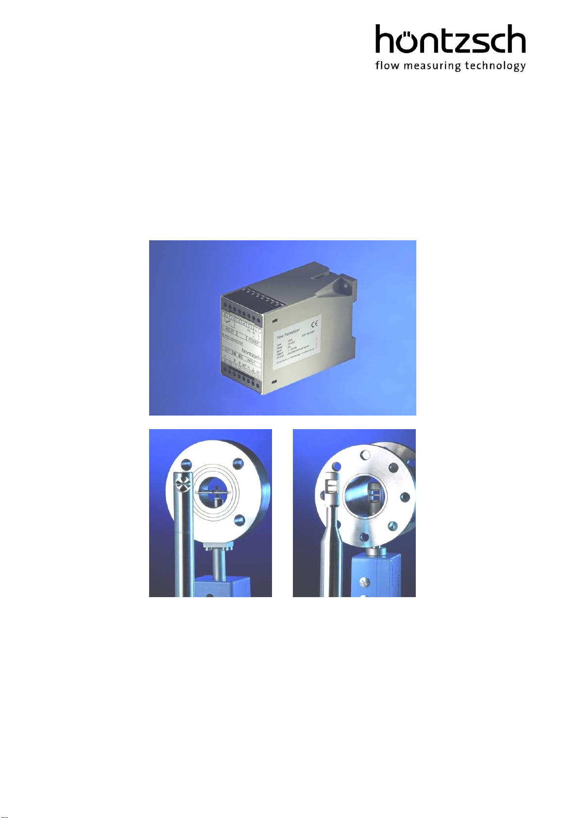
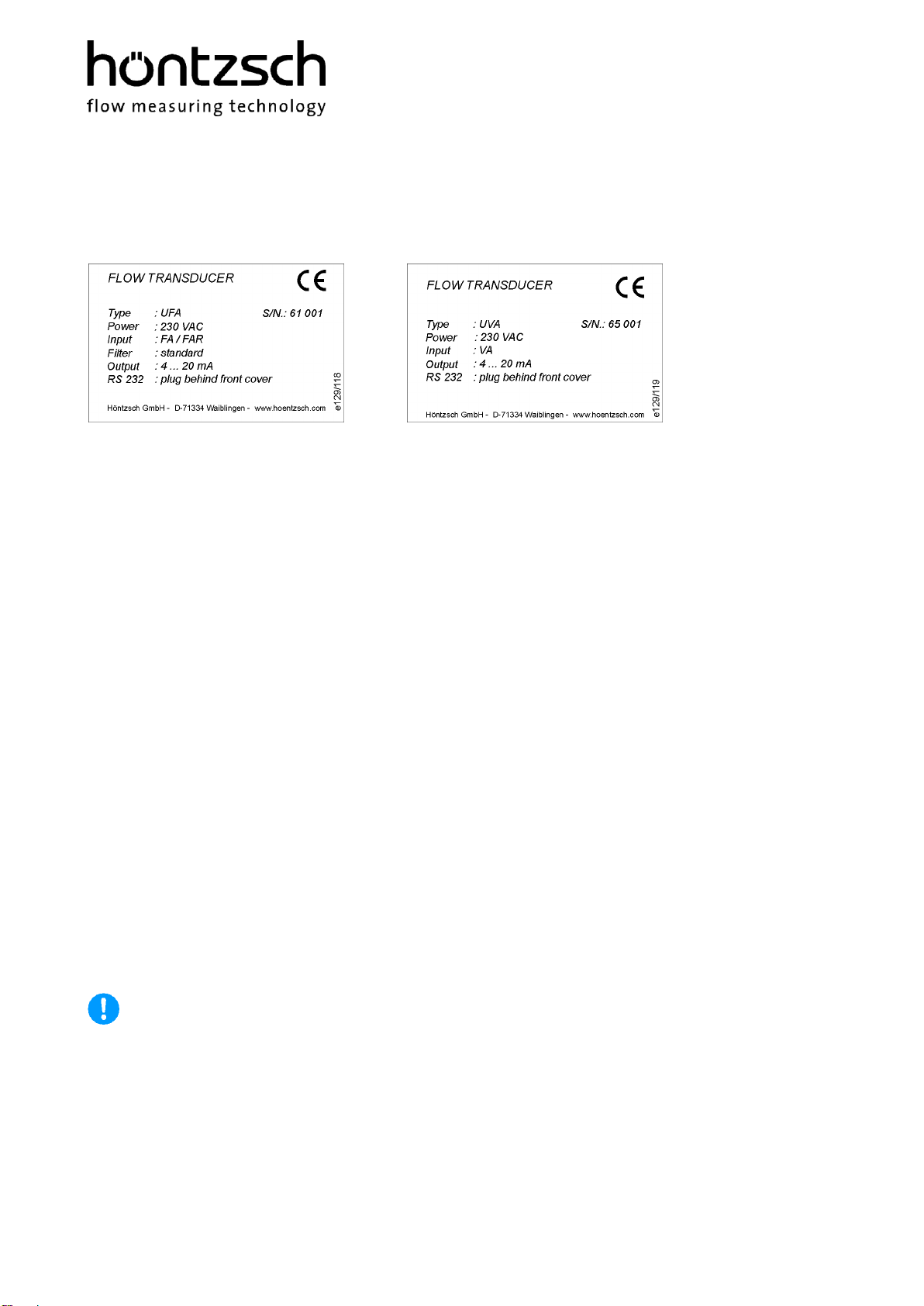
UFA transducers are designed for connecting to vane wheel probes FA and FAR (directional sensing) and
vane wheel measuring tubes FA Di and FAR Di (directional sensing) for measuring flow velocity or flow
rate of air/gases and water/liquids.
UVA transducers are designed for connecting to vortex probes VA and vortex measuring tubes VA Di for
measuring the flow velocity or flow rate of air/gases.
The signal frequency proportional to the velocity generated from the flow sensor is converted to a linear
analog output signal 4-20 mA or 0-10 V. The analog terminal value is configurable. When logging direc-
tional sensing data the zero point can be selected in the middle of the analog range or directional sensing
takes place with the help of the relay output:
for FA and FAR*: 4 ... 20 mA = 0 ... x m/s (or m³/h)
for FAR: 4 ... 12 ... 20 mA = -x ... 0...+x m/s (or m³/h)
for VA: 4 ... 20 mA = 0 ... x m/s (or m³/h)
alternatively:
for FA and FAR*: 0 ... 10 V = 0 ... x m/s (or m³/h)
for FAR: 0 ... 5 ... 10 V = -x ... 0...+x m/s (or m³/h)
for VA: 0 ... 10 V = 0 ... x m/s (or m³/h)
* for FAR sensors for configuring the relay see under: ±direction of flow
The actual velocity or actual flow rate can be converted to standard velocity or standard flow rate by en-
tering the parameter for temperature and pressure.
A relay output (change-over contact) can be configured for 1 of 3 different functions:
1. as limit value for the flow velocity or the flow rate:
flow velocity < or = limit value: relay contact idle
flow velocity > limit value: relay contact in working position
2. as quantity pulse for quantity measurement:
max. pulse repetition frequency 1 Hz per unit of volume,
configurable, e.g. 1 pulse per 1, 10 or 100 (norm)-m³ or (norm)-litre
pulse duration 0.1 s (FAR sensors: configurable for '+' or '-' amounts)
3. as ±direction of flow ** (for FAR sensors only):
+direction: relay contact in idle
- direction: relay contact in in working position
** analog output (see above) is then absolute value of flow only, without direction
Self diagnosis according to NAMUR NE43:
No error: yellow LED off
green LED on (flow velocity = 0) or
green LED flashes (flow velocity > 0)
Error: yellow LED on and with
- analog output 4-20 mA : < 3.6 mA
- analog output 0-10 V : < -0.2 V
Monitored: power supply, data logging, sensor interface, parameter settings (see under 16: Trouble-
shooting)
PC serial port RS232:
for changing calibration data and setting parameters.
Remove front cover (see Fig. 1)
Plug PC connector cable (optional) with RJ22 into the socket in the transducer (see Fig. 2).
Connect other end of cable to PC COM port.
If a USB connection is required, then an optional USB / RS232 interface converter must be inserted.
Changes to the settings can now take place after starting the PC programme UCOM (optional)
(see under 8: Settings).

__________________________________________________________________________________________________
______________________________________________________________________________________
U327_UFAUVALDG16_B_e_170808 www.hoentzsch.com 11/15
8 Settings
The following setting parameters can be read using the PC software UCOM and are also alterable.
The customer-specific settings are shown on the parameter print-out, which is included in the
documents.
Please find operation instructions PC software UCOM in document U385.
9 Performance Test
sensor not connected
(pay attention to 6.2.1 Power supply and 6.2.3 Analog output)
after connecting the supply voltage the green and yellow LED light up.
The analog output sends a value between 3.4 mA and 3.6 mA with output current or between –0.3 V and
–0.2 V with output voltage.
10 Initial Operation
sensor connected
(pay attention to 6.2.1 Power supply, 6.2.2 Sensor input and 6.2.3 Analog output)
after connecting the supply voltage the green LED lights up and the yellow LED is off.
No flow at sensor: the green LED is permanently on, the analog output sends a value of 4 mA with output
current (or 12 mA depending on configuration with FAR sensors) or with output voltage a value of 0 V (or
5 V depending on configuration with FAR sensors, see under 7 Functional Description)
Flow at sensor: the green LED flashes, the analog output sends an analog value deviating from the zero
flow conditions (see above).
11 Operation
(Pay attention to 5.3 Operating Conditions and 5.6 Electrical Data)
12 Shut-down, Dismantling
Before disconnecting the cable, please ensure that the supply voltage is switched off.

________________________________________________________________________________________
______________________________________________________________________________________
12/15 www.hoentzsch.com U327_UFAUVALDG16_B_e_170808
13 Inspection
Checking the LEDs, (see under 7 Functional Description, Self diagnosis)
14 Maintenance
Only use cleaning agents which dry without leaving any residue and which are compatible with the hous-
ing materials.
15 Calibration
The UFA and UVA transducers have an excellent long-term stability. However, it makes sense to have the
instruments calibrated at certain intervals. The period between two calibrations depends on the individual
operational conditions and the tolerable measurement error. Therefore, as a precaution, shorter calibra-
tion cycles should be chosen at the beginning. As an indication and under 'normal' operating condi-
tions a calibration cycle of approx. 3-5 years applies.
Transducers must be returned to the manufacturer for calibration. Please refer to Section 17!

__________________________________________________________________________________________________
______________________________________________________________________________________
U327_UFAUVALDG16_B_e_170808 www.hoentzsch.com 13/15
16 Troubleshooting
Fault
Cause
Troubleshooting
green LED does not light
up
no power supply
check connecting cable, measure volt-
age at connecting terminals
transducer electronics faulty
return to factory
yellow LED lights up,
green LED does not flash
despite flow, analog
output = error (<3.6 mA
or < -0.2V)
cable break or short-circuit
check terminals,
check cable for continuity and replace if
necessary
transducer or sensor electronics
faulty
return to factory
yellow LED lights up,
green LED flashes with
flow, analog output =
error (<3.6 mA or
< -0.2V)
parameter error
check parameter with UCOM software,
save new checksum
(or return to factory)
transducer electronics faulty
return to factory
no measured value
sensor contaminated
clean sensor according to instructions
profile factor set at 0.000
set profile factor at '1.000'
measured value too low
sensor contaminated
clean sensor according to instructions
profile factor set too low
set profile factor at '1.000'
input/output section too short
change sensor position, improve flow
conditions with a flow rectifier
rotational flow
reposition sensor in flow direction, in-
stall flow rectifier
vortex VA sensors:
reduced acoustic coupling in the
sensor elements as a result of
intense vibration or powerful
impact
return sensor to factory for performance
test
burden at current ouput is
greater than specified in the
Technical Data Sheet resulting
in correct output values in the
lower range and no longer in-
creasing values at the top end
of the measuring range
reduce resistance
incorrect scaling of analog out-
put
check setting and amend if necessary
measured value too high
profile factor set too high
set profile factor at '1.000'
EMC problem
see under 6.3

________________________________________________________________________________________
______________________________________________________________________________________
14/15 www.hoentzsch.com U327_UFAUVALDG16_B_e_170808
17 Returns
No special measures necessary for UFA and UVA transducers.
When returning sensors, these should be cleaned thoroughly according to the instructions. A hazard warn-
ing or declaration of no objection must be supplied for substances which have been in contact with the
sensor or possibly infiltrated the cavities in the sensor. If adhesion of hazardous substances cannot be
ruled out, then detailed safety measures to be taken when handling the equipment must be itemised.
18 Disposal
The customer should assume the duty to dispose of the equipment at his own expense and according to
statutory provisions (e.g. ElektroG in Germany).
19 Replacement Parts
Fuse TR5 accessible by removing the front cover and
visible top right in Fig.3:
for 230 V AC TR5-T 100 mA order no. e025/023
for 24 V DC TR5-T 500 mA order no. e025/024
for 12 V DC TR5-T 500 mA order no. e025/024
The fuse is inserted in the base.
Always switch off before changing the fuse!
Fig.3 Fuse TR5

__________________________________________________________________________________________________
______________________________________________________________________________________
U327_UFAUVALDG16_B_e_170808 www.hoentzsch.com 15/15
20 Declaration of Conformity, Manufacturer’s Declaration
____________________________________________________________________________
We, Höntzsch GmbH & Co. KG
Gottlieb-Daimler-Straße 37
D-71334 Waiblingen
bearing sole responsibility, hereby declare that the product
Transducer UFA / UVA in LDG16 Housing
referred to in this declaration, is in conformity with the following standards or normative
documents:
Provisions of the Directive
Reference and date of issue
2014/30/EU: Electromagnetic Compatibility
EN 61000-6-4
EN 61000-6-2
2014/68/EU: Pressure Equipment Directive
2006/42/EC: Safety of Machinery
EN 61010
Waiblingen, 17.09.2019 Jürgen Lempp / Managing Director
Höntzsch GmbH & Co. KG
Gottlieb-Daimler-Straße 37
D-71334 Waiblingen (Hegnach)
Tel: +49 7151 / 17 16-0
Fax: +49 7151 / 5 84 02
E-Mail info@hoentzsch.com
Internet www.hoentzsch.com
Subject to alteration
Other manuals for UVA
2
This manual suits for next models
1
Table of contents
Other Hontzsch Transducer manuals
Popular Transducer manuals by other brands

NK TECHNOLOGIES
NK TECHNOLOGIES ATQ Series instructions

MTS Systems
MTS Systems Temposonics II LDT Installation and instruction manual

Lumel
Lumel P20 User Manual & Quick Start

Milltronics
Milltronics PL-551 instruction manual

Humminbird
Humminbird Transducer Installation

Airmar
Airmar Ultrasonic TRIDUCER UDST800 Owner's guide and installation instructions