Hope RF RFM12B User manual

RFM12B and AVR — quick start
1 Introduction
The RFM12B tranceiver module has become quite popular recently due
to its low price comparing to other modules on the market. But many
people find it hard to make these tranceivers work (mainly because of buggy
programming guide provided by manufacturer, I guess...). This short article
contains compact and simple code that can be used just to get these modules
running for the first time. It is based on manufacturer’s examle code with
slight (but crucial) changes.
2 Schematic
To interface RMF12B modules I used Atmel’s ATtiny2313. Schematic is
shown on figure 1. Recommended power supply for the module is 3.8V so I
decided to power both the processor and the module from 3.3V. It can be a
problem with the Mega family as you will need ”L”version then. Some people
claim that they run those modules from 5V and everything’s fine. The other
solution is splitted power supply (5V for processor and 3.3V for RFM12B)
but resistors are needed on IO pins (5kΩ or so) in this case. Implementing
SPI interface doesn’t require strict time delays or clock stability so processor
is running on the 8MHz internal RC oscillator.
3 Transmitter code
Full source code for both the transmitter and the receiver can be found in
rfm12b.zip1. Transmitter part contains functions supporting RS232 trans-
mission, but you can omit them as they are not used in the there. First, we
define some macros to keep the program clear.
1http://loee.jottit.com/rfm12b and avr - quick start
1

Figure 1. Circuit schematic
/* RFM12B INTERFACE */
#define SCK 7 // SPI clock
#define SDO 5 // SPI Data output (RFM12B side)
#define SDI 6 // SPI Data input (RFM12B side)
#define CS 4 // SPI SS (chip select)
#define NIRQ 2 // (PORTD)
/* IO CONTROL */
#define HI(x) PORTB |= (1<<(x))
#define LO(x) PORTB &= ~(1<<(x))
#define WAIT_NIRQ_LOW() while(PIND&(1<<NIRQ))
/* LED */
#define LED 6
#define LED_OFF() PORTD &= ~(1<<LED)
#define LED_ON() PORTD |= (1<<LED)
Then simple ports initialization. SCK, SDI, CS pins configured as outputs.
void portInit() {
HI(CS);
HI(SDI);
LO(SCK);
DDRB = (1<<CS) | (1<<SDI) | (1<<SCK);
DDRD = (1<<LED);
}
SPI can be implemented using hardware help (USI) but I decided to do it
in software. Next function takes a 16-bit long argument and sends it to the
module over SPI.
2

unsigned int writeCmd(unsigned int cmd) {
unsigned char i;
unsigned int recv;
recv = 0;
LO(SCK);
LO(CS);
for(i=0; i<16; i++) {
if(cmd&0x8000) HI(SDI); else LO(SDI);
HI(SCK);
recv<<=1;
if( PINB&(1<<SDO) ) {
recv|=0x0001;
}
LO(SCK);
cmd<<=1;
}
HI(CS);
return recv;
}
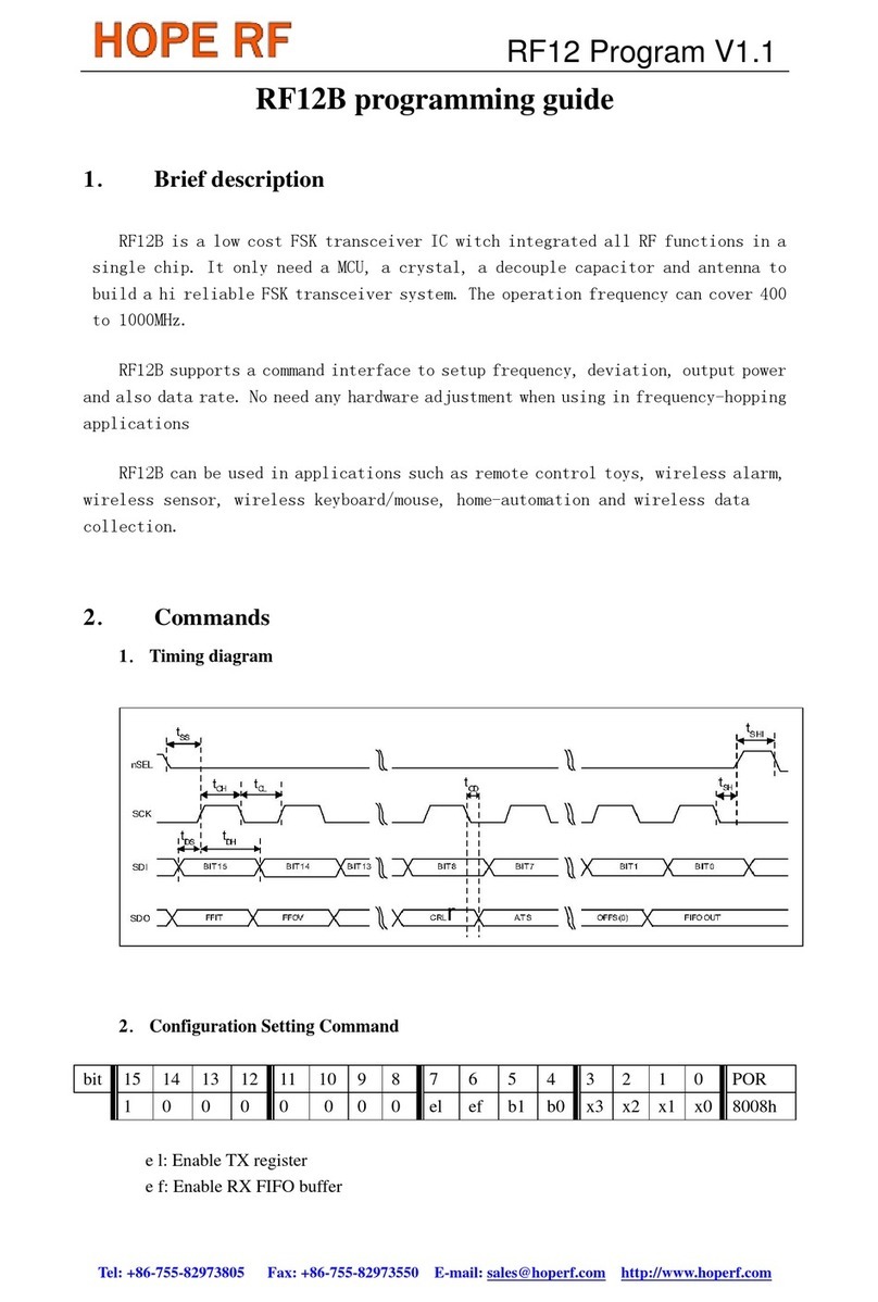
Initialization of radio module was taken from the ”Programming Guide”. All
I changed was first command (868MHz band instead of 434MHz). There is
one more function — sending one char to be transmitted. When module is
configured in tranmitter mode NIRQ goes low when previous data has been
sent. So all is to do is to wait for this to happen.
void rfInit() {
writeCmd(0x80E7); //EL,EF,868band,12.0pF
writeCmd(0x8239); //!er,!ebb,ET,ES,EX,!eb,!ew,DC
writeCmd(0xA640); //frequency select
writeCmd(0xC647); //4.8kbps
writeCmd(0x94A0); //VDI,FAST,134kHz,0dBm,-103dBm
writeCmd(0xC2AC); //AL,!ml,DIG,DQD4
writeCmd(0xCA81); //FIFO8,SYNC,!ff,DR
writeCmd(0xCED4); //SYNC=2DD4 ,
AG
writeCmd(0xC483); //@PWR,NO RSTRIC,!st,!fi,OE,EN
writeCmd(0x9850); //!mp,90kHz,MAX OUT
writeCmd(0xCC17); //OB1 ,
ACOB0, LPX,Iddy,CDDIT,CBW0
writeCmd(0xE000); //NOT USED
writeCmd(0xC800); //NOT USED
writeCmd(0xC040); //1.66MHz,2.2V
}
void rfSend(unsigned char data){
while(WAIT_NIRQ_LOW());
writeCmd(0xB800 + data);
}
All that is left is the main loop. First there is a slight delay after power-on-
reset. Then comes ports and module initialization. After that circuit is ready
to start the transmission. Frame format is taken from the datasheet 2— first
comes preamble (0xAA or 0x55), then synchronization pattern (0x2DD4)
followed by the payload. Last 3 dummy bytes are optional. Important
2RF12B datasheet p.25 (note this is the datasheet for IC, not module)
3

thing is to remember to read status register (writeCmd(0x0000)) before
each frame (without that line my transmitter was dead).
int main() {
volatile unsigned int i,j;
asm("cli");
for(i=0;i<1000;i++)for(j=0;j<123;j++);
portInit();
rfInit();
while(1){
LED_ON();
writeCmd(0x0000);
rfSend(0xAA); // PREAMBLE
rfSend(0xAA);
rfSend(0xAA);
rfSend(0x2D); // SYNC
rfSend(0xD4);
for(i=0; i<16; i++) {
rfSend(0x30+i);
}
rfSend(0xAA); // DUMMY BYTES
rfSend(0xAA);
rfSend(0xAA);
LED_OFF();
for(i=0; i<10000; i++) // some not very
for(j=0; j<123; j++); // sophisticated delay
}
}
4

4 Receiver code
Here things get a little bit inconsistent with the ”Programming Guide”.
Macros, port initialization and SPI handling in the receiver part is the same
as before so I will omit some code. The easiest way to check received data
is to send it to the PC. To do this we need some RS232 handling functions.
#define BAUDRATE 25 // 19200 at 8MHz
void rsInit(unsigned char baud) {
UBRRL = baud;
UCSRC = (1<<UCSZ0) | (1<<UCSZ1); // 8N1
UCSRB = (1<<RXEN) | (1<<TXEN); // enable tx and rx
}
void rsSend(unsigned char data) {
while( !(UCSRA & (1<<UDRE)));
UDR = data;
}
unsigned char rsRecv() {
while( !(UCSRA & (1<<RXC)));
return UDR;
}
Initialization of the module is almost the same. Only difference is quite
obvious — we need to turn on the reveiver instead of the transmitter. Sur-
prisingly, it is not so obvious for authors of the ”Programming Guide”. Their
initialization is the same no matter what they want to do. It’s the chineese
way I guess... ;) Anyway I recommend to turn on the receiver this time
(command no. 2).
void rfInit() {
writeCmd(0x80E7); //EL,EF,868band,12.0pF
writeCmd(0x8299); //er,!ebb,ET,ES,EX,!eb,!ew,DC (bug was here)
writeCmd(0xA640); //freq select
writeCmd(0xC647); //4.8kbps
writeCmd(0x94A0); //VDI,FAST,134kHz,0dBm,-103dBm
writeCmd(0xC2AC); //AL,!ml,DIG,DQD4
writeCmd(0xCA81); //FIFO8,SYNC,!ff,DR (FIFO level = 8)
writeCmd(0xCED4); //SYNC=2DD4;
writeCmd(0xC483); //@PWR,NO RSTRIC,!st,!fi,OE,EN
writeCmd(0x9850); //!mp,90kHz,MAX OUT
writeCmd(0xCC17); //!OB1,!OB0, LPX,!ddy,DDIT,BW0
writeCmd(0xE000); //NOT USE
writeCmd(0xC800); //NOT USE
writeCmd(0xC040); //1.66MHz,2.2V
}
Now it’s time for receiving functions. They are totally different from what
you can find in the mentioned, glorious ”Programming Guide”. To be honest,
I have no idea how their code could work at all... So, referring to the
5

RF12B datasheet, page 25, reception can be done either in interrupt mode
or polling mode. To choose interrupt mode we need to have FFIT/DCLK
pin connected to the processor. Because I haven’t got than pin connected
on my PCB I had to implement the polling mode. In this mode I read status
register (the same datasheet, page 23) and check first bit (FFIT) in a loop.
Once it is set, there is a valid data in FIFO buffer.
After receiving all data I reset FIFO buffer using FIFOReset() function. It
operates on FIFO and Reset Mode Command (RF12B datasheet, page 17).
There is a bit called ff. When we clear and set this bit the FIFO buffer is
cleared and module waits for the new synchronization pattern.
unsigned char rfRecv() {
unsigned int data;
while(1) {
data = writeCmd(0x0000);
if ( (data&0x8000) ) {
data = writeCmd(0xB000);
return (data&0x00FF);
}
}
}
void FIFOReset() {
writeCmd(0xCA81);
writeCmd(0xCA83);
}
Finally, we get to the main function. It receives 16 bytes of data and sends
it to PC in an infinite loop. It then resets FIFO buffer and waits for a new
transmission (with synchronization pattern). To check results you can use
any RS232 terminal (under Windows it can be HyperTerminal). On the
screen you should see numbers from 0 to 9 plus some other chars (from 0x30
to 0x3F in hex).
int main(void) {
unsigned char data, i;
LED_ON();
portInit();
rfInit();
rsInit(BAUDRATE);
FIFOReset();
while(1) {
//waitForData();
for (i=0; i<16; i++) {
data = rfRecv();
rsSend(data);
}
FIFOReset();
}
return 0;
}
6

5 Remarks
Because FFIT bit is the first bit in status register you can read only this
one instead of all 16 bits. What’s more, it should be set before SCK pin
goes high, so it should be possible to read it without clock or even connect
it directly to the pin handling external interrupt (some people claim to do
so). I haven’t tried any of this possibilities yet, so if you’re interested you
can investigate it on your own.
Good luck!
6 Useful links
Manufacturer’s documentation:
- IC datasheet http://www.hoperf.com/pdf/RF12B.pdf
- module datasheet http://www.hoperf.com/pdf/RFM12B.pdf
- Programming Guide http://www.hoperf.com/pdf/RF12B code.pdf
Other links:
- http://www.embedds.com/interfacing-rfm12-transceiver-module/
- http://electronics-diy.com/electronic schematic.php?id=725
- http://svn.everythingrobotics.com/strobist/mk1/trunk/arch/pic16f88-
boostc/src/
- http://www.mikrocontroller.net/topic/67273
- http://www.mikrocontroller.net/articles/AVR RFM12
7
Table of contents
Other Hope RF Transceiver manuals