HopeRF CMT2310A-EB User manual

AN241
www.hoperf.com
Copyright © By HOPERF
V 0.5 | Page 1/41
Overview
This Document introduces how to operate the CMT2310A-EB evaluation board (factory default firmware). The
CMT2310A-EB (factory default firmware) and CMT2310A-EM help users quickly evaluate the performance of
the CMT2310A. Meanwhile, CMT2310A-EB can help users to debug, verify and test the CMT2310A functions,
basing on the hardware as a general CM0 level single chip development board.
Part number covered in this document is shown as follow.
Table 1. Part number covered in this document
Part Number Freq. Demodulation Function Configuration Package
CMT2310A 113 – 960 MHz (G)FSK
High performance RF
transciever
Register QFN24
Reading guideline:
1. Before reading this document, it is advised to read the CMT2310A Data manual first to understand the
functions and performance of the CMT2310A.
2. When using the evaluation board, please refer to the following related AN for further understand the
CMT2310A function configuration options:
a) AN235 CMT2310A FIFO and Packet Format Useage Guide
;
b) AN236 CMT2310A Register Description
;
c) AN237 CMT2310A Quick Start Guide
;
d) AN238 CMT2310A RF Parameter Configuration Guide
;
e) AN239 CMT2310A Auto-transceiver Usage Guide
CMT2310A-EB Evaluation Board User Guide
AN241

AN241
www.hoperf.com
Copyright © By HOPERF
V 0.5 | Page 2/41
Table of Contents
1Hardware Platform Introduction..............................................................................................................3
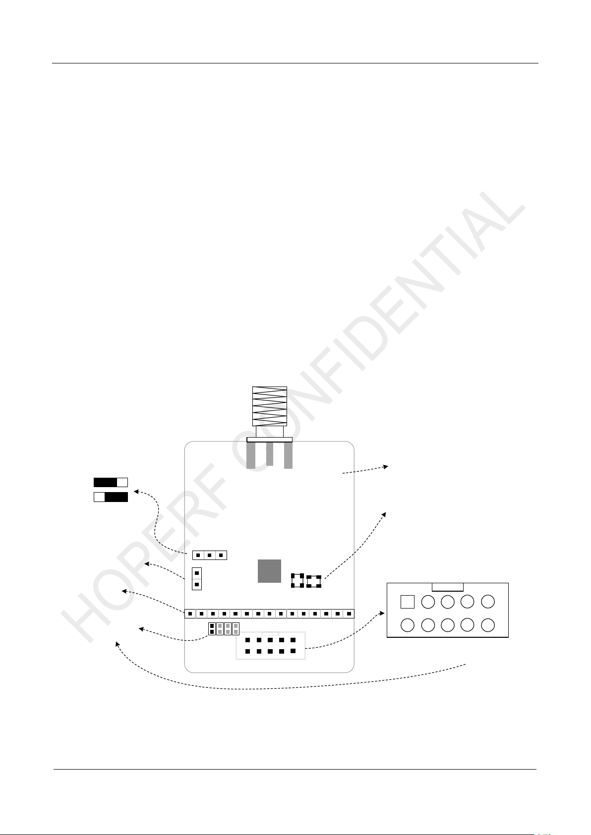
1.1 CMT2310A-EM Introduction............................................................................................................. 3
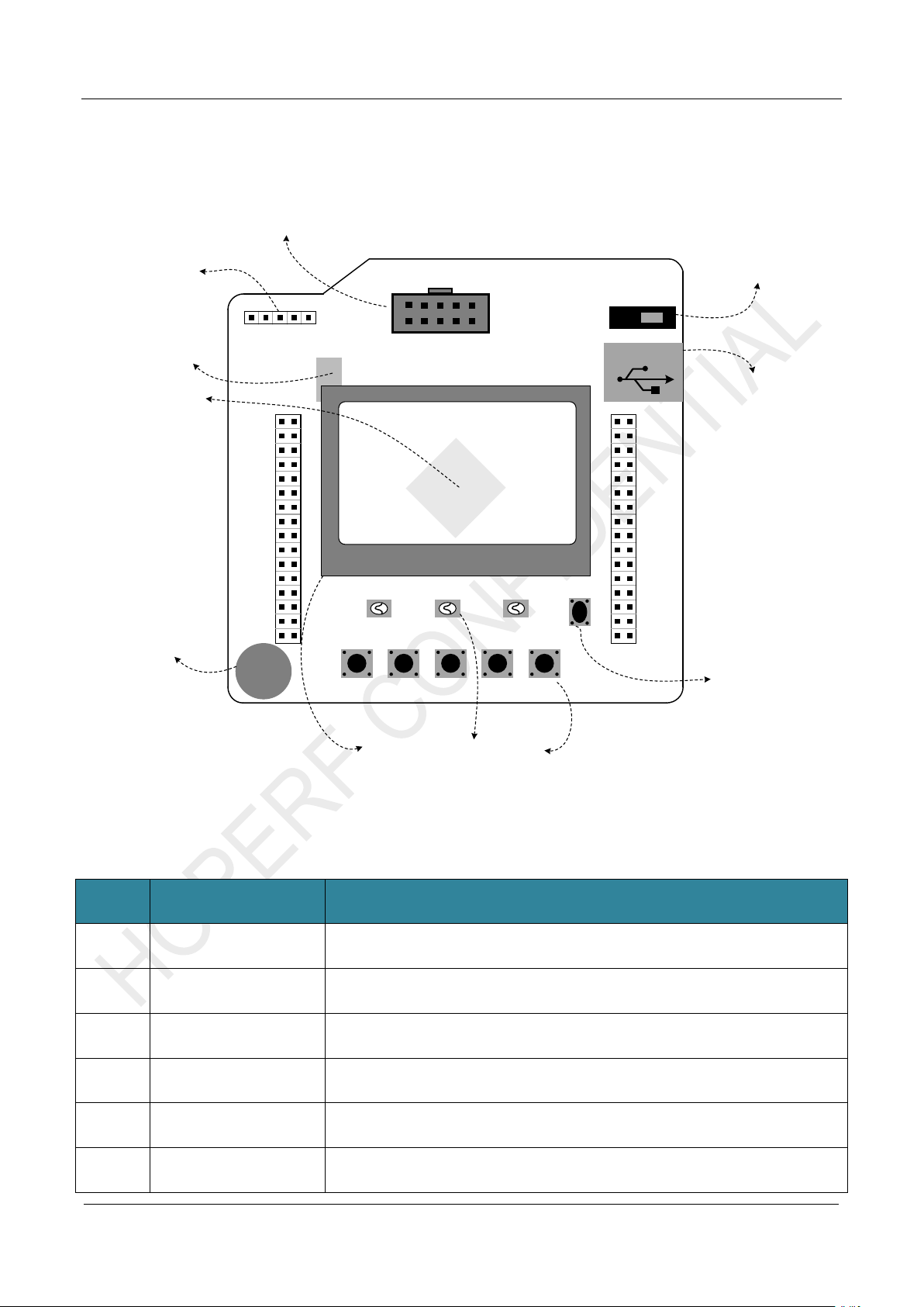
1.2 CMT2310A-EB Introduction.............................................................................................................. 5
2Parameter Setting .....................................................................................................................................7
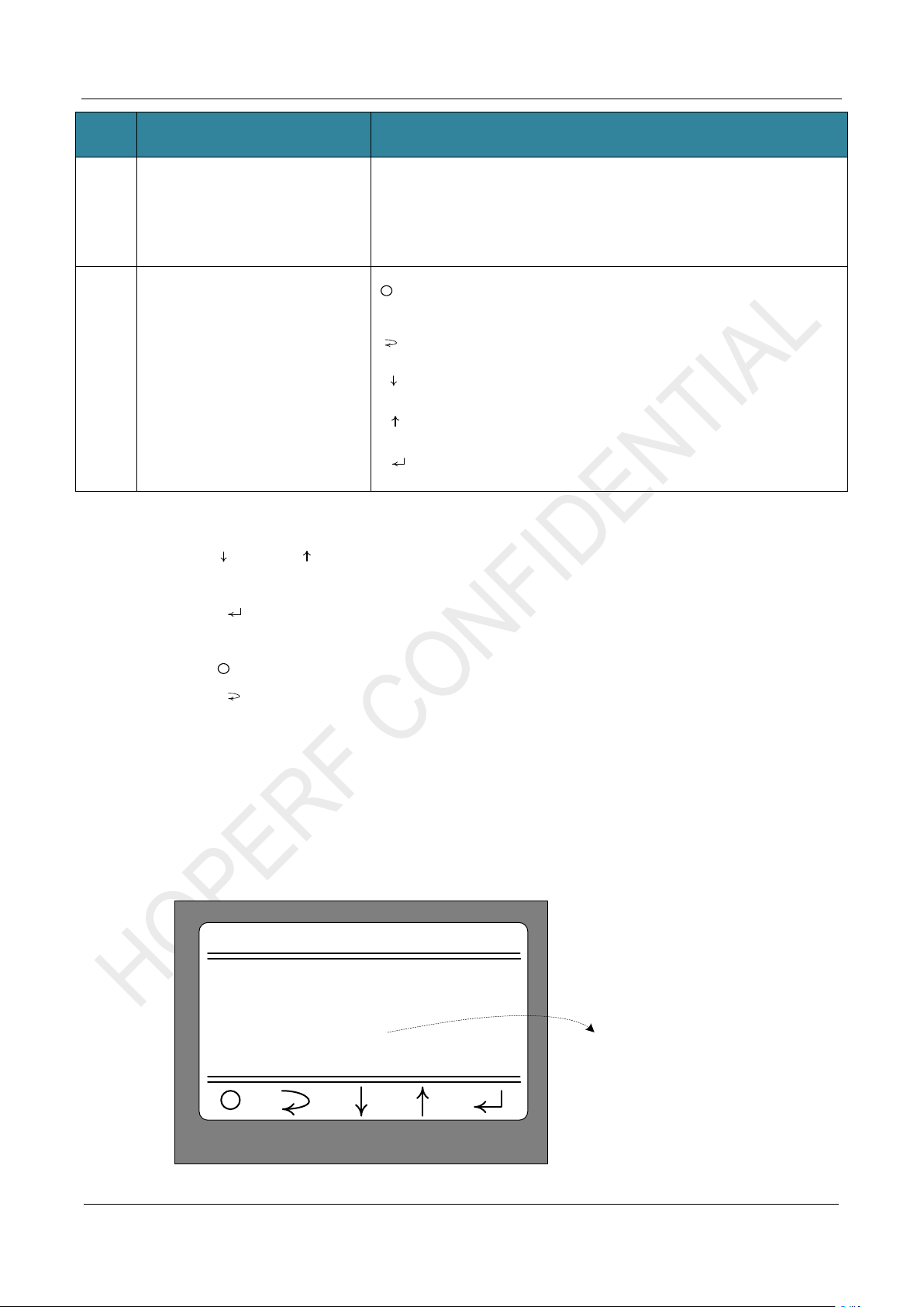
2.1 Startup Interface............................................................................................................................... 7
2.2 Main Menu........................................................................................................................................ 8
2.3 Modulation Submenu........................................................................................................................ 9
2.4 Work Mode Submenu..................................................................................................................... 10
2.5 Frequencry Band Submenu.............................................................................................................11
2.6 Data Rate Submenu........................................................................................................................11
2.7 Tx Output Power Submenu............................................................................................................ 13
2.8 Preamble Length Submenu............................................................................................................ 14
2.9 Packet Length Submenu ................................................................................................................ 14
2.10 Coding Format Submenu ............................................................................................................... 15
2.11 CRC Select Submenu .................................................................................................................... 16
2.12 Packet Structure............................................................................................................................. 17
2.13 Frequencry Space and Frequencry Channel Submenu................................................................. 18
2.14 DC DC Select Submenu................................................................................................................. 19
2.15 Gaussian Select Submenu............................................................................................................. 20
2.17 Payload Content Submenu............................................................................................................. 22
3Working Mode ........................................................................................................................................ 23
3.1 Sleep Mode..................................................................................................................................... 23
3.2 CW Tx Mode................................................................................................................................... 24
3.3 Direct Rx Mode............................................................................................................................... 26
3.4 Only Tx Mode ................................................................................................................................. 27
3.5 Only Rx Mode................................................................................................................................. 29
3.6 Tx and Rx Mode ............................................................................................................................. 31
4Supplymentary....................................................................................................................................... 34
4.1 Firmware Update Burning Operation.............................................................................................. 34
4.2 Corresponding Mode for Each Function/Indicator.......................................................................... 38
5Revise History........................................................................................................................................ 40
6Contacts.................................................................................................................................................. 41

AN241
www.hoperf.com
Copyright © By HOPERF
V 0.5 | Page 3/41
1 Hardware Platform Introduction
The CMT2310A evaluation board hardware test platform is composed of CMT2310A-EB and CMT2310A-EM:
CMT2310A-EB is the test panel of the evaluation board, using HC32L136 as the development board
of the CMT2310A module, factory set with CMT2310A function and performance evaluation firmware,
and can also be used as the CMT2310A development board.
CMT2310A-EM is the evaluation module, and the module is affixed according to the matching
parameters of the target frequency band (2 common frequency bands are provided: 434MHz and
868MHz with transmission power of +20dBm Direct Tie hardware matching mode), which can be
used by users for evaluation before scheme selection or reference comparison in design.
CMT2310A-EM also supports to connect to the RFPDK upper computer interface software through
USB Programmer and realizes online control of the CMT2310A functional testing and verification.
1.1CMT2310A-EM Introduction
The following figure shows the top view and introduction of CMT2310A-EM
GND
R4
R5
R3
VDD
VCC
R2
VDD_PA
GPIO3
GPIO5
GPIO4
VIN
GPIO2
SCLK
SDO
SDI
NC
CSB
NC
NIRQ
GPIO1
GPIO0
CMT2310A
X1 X2
CMOSTEK
CMT2310A-EM
Rev xxx
Direct Tie
1. DC-DC Select
OFF
ON
2. Current Detect
3. Test Pin
4. GPIO2~GPIO5
Connect Select
6. Crystal
X1: for Passive Crystal OSC.
X2: for TCXO
5. EM Version Information
12
34
56
78
9
GND
VCC SDO
SDI
10
NIRQ
GPIOn
GPIO0GPIO1
SCLK
CSB
7. EM Connector
Figure 1-1. CMT2310A-EM Introduction

AN241
www.hoperf.com
Copyright © By HOPERF
V 0.5 | Page 4/41
Table 1-1. CMT2310A-EM Description
No. Function Description
1 DC-DC Select
CMT2310A has an embedded DC-DC module. You can select the DC-
DC mode or disable it. Noted that this jumper is a hardware choice and
needs to combine with the control software. If you want to enable the
DC-DC module, the software also needs to configure the
corresponding register BUCK_SEL to 1 (located in Page1, address
0x01, Bit4).
2 Current Detect The power consumption of CMT2310A in each working state can be
determined by connecting the current test jumper to the ammeter.
3 Test Pin Test points of each pin of CMT2310A
4 GPIOn Select
R2-R5 is corresponding to GPIO2-GPIO5 and the 0R resistor is used
as selection of GPIOn according to GPIO2-GPIO5. If the factory default
is R4, that is, select the GPIO4 as GPIOn.
Note: Only supported by Ver003, not compatible with old versions.
5 EM Version Information The current CMT2310A-EM version information is Ver003.
6 Crystal
Crystal mode
:
The X1 is patched with crystal;
The X2 patch position crystal is TCXO, and the TCXO power supply is
provided by the NIRQ pin of the CMT2310A.
Note
:
Only supported by Ver003, not compatible with old versions.
7 EM Connector The 10 pins connector of CMT2310A-EM is defined as shown in the
figure.
Note
:
1. For more information of CMT2310A-EM, please refer to its schematic diagram - CMT2310A-EM revXXX SCH.pdf
2. Since this firmware requires GPIO4, make sure that on CMT2310A-EM, GPIOn selects GPIO4, that is, R4 is patched with
0R.

AN241
www.hoperf.com
Copyright © By HOPERF
V 0.5 | Page 5/41
1.2CMT2310A-EB Introduction
The following figure shows the top view and introduction of CMT2310A-EM
VDD
CMOSTEK
K1 K2 K3
CMOSTEK
SW 20220712 FW C0
K4 K5
LED1LED2LED3
RST
RF-EB Rev-003
Power On/Off
USB TypeB
GND
PB11 PB10
PB02 PB01
PB00 PC05
PC04 PA07
PA06 PA05
PA04 PD05
PD04 PA03
PA02 PA01
PA00 AVDD
GND PC03
PC02 PC01
PC00 RSTB
GND GND
GND GND
PC13 VCAP
PB12 PB13
PB14 PB15
PC06 PC07
PC08 PC09
PA08 PA09
PA10 PA11
PA12 PA13
PD06 PD07
PA14 PA15
PC10 PC11
PC12 PD02
PB03 PB04
PB05 PB06
PB07 BOOT
PB08 PB09
GND VDD
4. HC32L136
EB Main Contorller
2. J-Link Debug
Interface
1. CMT2310A-EM
Connector
GND
SWCLK
SWDIO
VDD
RSTB
3. CH340G
USB to UART Interface
8. USB TypeB Connector
9. Power Switch
7. Reset Key
5. Buzzer
6. User Interface (LCD, LED, Key)
Figure 1-2. CMT2310A-EB Introduction
Table 1-2. CMT2310A-EB Description
No. Function Description
1 CMT2310A-EM Connector Connect the 10PIN base of CMT2310A-EM and connect the HC32L136 control pin as
shown in the table below
2 J-link Debug Interface J-link debug interface(SWD)
3 CH340G
USB to UART Interface CH340G USB to UART interface chip (HC32L136 controller PB06 is TxD, PB07 is
RxD)
4 HC32L136
EB Main Controller Eb board main controller HC32L136。
5 Buzzer Direct beeper on EB board
6 User Interface EB board operation interface:
1. LCD display(128x64 lattice);

AN241
www.hoperf.com
Copyright © By HOPERF
V 0.5 | Page 6/41
No. Function Description
2. LED1~LED3 status indicator
;
3. K1~K5 operation key;
Specific connection control pins of HC32L136 are shown in the table below
7 Reset Key HC32L136 reset control key
8 USB TypeB Connector USB B connector, can supply power to EB via the USB
9 Power Switch Switching the EB board is power from USB or battery (AA dry battery X3).
Table 1-3. CMT2310A-EB Pin Function of the Main Controller HC32L136
Pin
Function
Pin
Function
Pin
Function
Pin
Function
PB12 LCD_CS
PB13 LCD_RST
VDD --
GND --
PB14 LCD_RS PB15 LCD_SDA PB11 -- PB10 --
PC06 LCD_SCK PC07 LCD_LED PB02 RF_NIRQ PB01 RF_GPIO1
PC08 -- PC09 -- PB00 RF_GPIO0 PC05 --
PA08 -- PA09 -- PC04 RF_GPIOn PA07 RF_SDI
PA10 -- PA11 -- PA06 RF_SDO PA05 RF_SCLK
PA12 -- PA13 SWCLK PA04 RF_CSB PD05 --
PD06 -- PD07 -- PD04 -- PA03 --
PA14 SWDIO PA15 -- PA02 -- PA01 --
PC10 LED3 PC11 LED2 PA00 -- AVDD
PC12 LED1 PD02 Buzzer GND PC03 --
PB03 K5 PB04 K4 PC02 -- PC01 --
PB05 K3 PB06 UART_TxD PC00 -- RSTB RST_KEY
PB07 UART_RxD BOOT -- GND -- GND --
PB08 K2 PB09 K1 GND -- GND --
GND -- VDD -- PC13 -- VCAP --
Note
:
1. For more information of CMT2310A-EB, please refer to its schematic diagram - CMT-RF_EB revXXX
SCH.pdf
In summary, CMT2310A-EB can be regarded as a development board with HC32L136 as the main control,
which provides a variety of user-computer interaction interfaces (LCD lattice, beeper, LED, keys, USB-to-
UART bridge, etc.). Meanwhile, CMT2310A-EM is equipped with a 10 PIN master socket, which is very
suitable for function familiarization, debugging, verification and testing of CMT2310A.

AN241
www.hoperf.com
Copyright © By HOPERF
V 0.5 | Page 7/41
2 Parameter Setting
Based on CMT2310A-EB and CMT2310A-EM, a firmware for testing and evaluation of multiple functions of
CMT2310A chip will be pre-burned at the factory. This firmware will be updated according to functional
changes. You can download it from the official website of Hope Microelectronics Co., LTD., and use the J-link
debugger and use J-Flash software for burn update (Chapter 4 of this article will describe the firmware update
in detail).In the following section, parameter setting menu of the factory firmware will be described in detail.
2.1Startup Interface
After CMT2310A-EM is inserted into CMT2310A-EB, the startuo interface is shown as followed.
CMOSTEK
SW 20220712 FW C0
1. HC32L136
Software Version
2. CMT2310A
Firmware Version
Figure 2-1. Startup Interface(After inserted CMT2310A-EM)
No. Function Description
1 HC32L136 Software Version CMT2310A-EB factory firmware (HC32L136 burning software) version
information, as shown in the figure above, is 20220712
2 CMT2310A Firmware Version
CMT2310A firmware version (that is, firmware version of the CMT2310A
chip on the CMT2310A-EM). As shown in the figure above, the current
chip version is C0.
Note: As of this document, there are three versions of firmware: A0, B0,
and C0, and C0 is the latest one.
When the CMT2310A-EM is not inserted into CMT2310A-EB, the startup interface of the CMT2310A-EB
is shown in Figure 2-2.

AN241
www.hoperf.com
Copyright © By HOPERF
V 0.5 | Page 8/41
not found CMT2310A
Figure 2-2. Startup Interface(not inserted CMT2310A-EM)
2.2Main Menu
After the screen is powered on for about 1 second, the screen will switch to the normal menu mode, as shown
in Figure 2-3 below. (If the CMT2310A-EM is not inserted properly or the CMT2310A chip cannot be identified,
the screen will remain in the display state as shown in Figure 2-2 until CMT2310A-EM is inserted properly or
CMT2310A can be recognized normally.)
CMT2310A EB GUI
1 Modulation
2 Work Mode
3 Frequencry Band
4 Data Rate
2. Submenu selection
area
1. Title
3. Corresponding
key function area
Figure 2-3. Main Menu Interface
No. Function Description
1 Title area CMT2310A EB GUI
2 Submenu selection area
13 submenu selections are shown in the area
1. Modulation(Modulation and demodulation mode selection)
2. Work Mode(Working mode selection)
3. Frequencry Band(Frequency band selection)
4. Data Rate(Rate/frequency offset parameter selection)
5. Tx Output Power(Transmission power selection)
6. Preamble Length(Preamble length selection)
7. Packet Length
(
Packet length selection
)

AN241
www.hoperf.com
Copyright © By HOPERF
V 0.5 | Page 9/41
No. Function Description
8. Coding Format
(
Coding format selection
)
9. CRC Select(CRC verification mode selection)
10. Freq Space(Frequency offset interval setting)
11. Freq Channel(Frequency channel signal setting)
12. DC-DC Select(DC-DC mode selectio)
13. Gaussian Select
(
Gaussian mode selection
)
3 Corresponding key
function area
5 buttons shown in this area with corresponding key of K1-K5
:it is corresponding to K1,indicates that CMT2310A EB will enter the
working state according to the parameters/modes set in the above menus
as short pressed;
:it is corresponding to K2,indicates that CMT2310AEB returns to
upper level menu directory as short pressed;
:it is corresponding to K3,indicates that CMT2310AEB selects the
next choice as short pressed;
:it is corresponding to K4, indicates that CMT2310A EB selects the
previous choice as short pressed;
:it is corresponding to K5,indicates that the current selection is
selected as short pressed
;
Operation description in main menu interface:
1. Press K3 ( ) and K4 ( ) to select the required modified item and the flash submenu item indicates
the current selected status.
2. Press K5()to enter the selected submenu item and select the corresponding subitem
parameter/mode
3. Press K1 ( ) to enter the corresponding working mode according to the current settings.
4. Press K2()to return to the upper-level menu. Since the current menu is already the upper-level
menu and cannot be returned, it will show no response on the interface.
2.3Modulation Submenu
Select 1 Modulation, and press K5 to enter the submenu, as shown in Figure 2-4 below.
CMT2310A EB GUI
1 Modulation
2FSK
1. Rolling option area

AN241
www.hoperf.com
Copyright © By HOPERF
V 0.5 | Page 10/41
Figure 2-4. Modulation Submenu Interface
No. Function Description
1 Rolling option area
3 modulation modes can be selected by pressing K3 or K4 in the area
:
OOK
2FSK
4FSK
After selecting the corresponding modulation mode, press K2 or K5 to
confirm the selection and return to the upper menu (i.e. the main menu).
2.4Work Mode Submenu
Select the 2 Work Mode and press K5 to enter the submenu, as shown in Figure 2-5.
CMT2310A EB GUI
2 Work Mode
Tx and Rx Mode
1. Rolling option area
Figure 2-5. Work Mode Submenu Interface
No. Function Description
1 Rolling option area
6 working modes can be selected by pressing K3 or K4 in the area
:
Sleep(enter into sleep mode)
CW Tx(enter into CW Tx mode)
Direct Rx(enter into direct Rx mode)
Only Tx Mode(enter into only Tx mode, one-way mode)
Only Rx Mode(enter into only Rx mode, one-way mode)
Tx and Rx Mode(enter into Tx and Rx mode – bidirectional mode)
After selecting the corresponding modulation mode, press K2 or K5 to
confirm the selection and return to the upper menu (i.e. the main menu).
Note: In the main menu state, the working mode is entered by pressing K1 ( ) in accordance with the
selected modes in sub-menu.

AN241
www.hoperf.com
Copyright © By HOPERF
V 0.5 | Page 11/41
2.5Frequencry Band Submenu
Select the 3 Frequencry Band and press K5 to enter the submenu, as shown in Figure 2-6.
CMT2310A EB GUI
3 Frequencry Band
433000kHz
1. Rolling option area
Figure 2-6. Frequencry Band Submenu Interface
No. Function Description
1 Rolling option area
The following 6 freqency band can be selected by pressing K3 or K4:
169000kHz(i.e. the start frequency is 169MHz)
230000kHz (i.e. the start frequency is 230MHz)
314000kHz (i.e. the start frequency is 314MHz)
433000kHz (i.e. the start frequency is 433MHz)
470000kHz (i.e. the start frequency is 470MHz)
779000kHz (i.e. the start frequency is 779MHz)
863000kHz (i.e. the start frequency is 863MHz)
902000kHz (i.e. the start frequency is 902MHz)
After selecting the corresponding modulation mode, press K2 or K5 to
confirm the selection and return to the upper menu (i.e. the main menu).
Note: This submenu is selected as the start frequency, because it can achieve frequency offsets through ferq.
Space and freq. Channel. For more information, please see at the Freq.Space and freq. Channel submenus
section below.
2.6Data Rate Submenu
Select the 4 Data Rate and press K5 to enter the submenu, as shown in Figure 2-7.

AN241
www.hoperf.com
Copyright © By HOPERF
V 0.5 | Page 12/41
CMT2310A EB GUI
4 Data Rate
20kbps 10kHz
1. Rolling option area
Figure 2-7. Data Rate Submenu Interface
No. Function Description
1 Rolling option area
This area can combine different rate/frequency offset by pressing K3 or
K4. Depending on the chosen modulation and demodulation mode, the
combinations provided are as follows
OOK mode:
-5kbps
-50kbps
-100kbps
-200kbps
-300kbps
2FSK mode:
-10kbps, 5kHz(i.e. data rate with 10kbps,offset with +/-
5kHz)
-20kbps, 10kHz
-50kbps, 25kHz
-100kbps, 50kHz
-200kbps, 100kHz
-500kbps, 250kHz
-2400bps, 1200Hz
4FSK mode:
-10kbps, 10kHz(i.e. data rate with 10kbps,offset of the outer
side with +/-10kHz)
-100kbps, 100kHz
-200kbps, 150kHz
-400kbps, 200kHz
-800kbps, 250kHz
-1Mbps, 250kHz
-1Mbps, 350kHz
After selecting the corresponding modulation mode, press K2 or K5 to
confirm the selection and return to the upper menu (i.e. the main menu).
Note
:
1. The combined parameters of rate/frequency offset provided in each modulation and demodulation mode
are basically corresponding to the test parameters in the CMT2310A data manual, so that users can
retest and confirm them.
2. For the rate/frequency offset combination parameters provided in each modulation and demodulation
mode, all the configuration parameters are derived from RFPDK, and the crystal deviation is set at 10ppm.

AN241
www.hoperf.com
Copyright © By HOPERF
V 0.5 | Page 13/41
Ony in the 2FSK mode, 2400bps, 1200Hz is set as the derived parameters of 2ppm. Therefore, when
setting this configuration, ensure that the CMT2310A-EM is tested in TCXO mode or the frequency
deviation of the two EMs is very small. Otherwise, the communication effect will be affected and the
performance will be indirectly misdiagnosed.
2.7Tx Output Power Submenu
Select the 5 Tx Output Power and press K5 to enter the submenu, as shown in Figure 2-8.
CMT2310A EB GUI
5 Tx Output Power
+20 dBm
1. Rolling option area
Figure 2-8. Tx Output Power Submenu Interface
No. Function Description
1 Rolling option area
In this area, different Tx power can be selected by pressing K3 or K4
:
-10 dBm
-7 dBm
-3 dBm
0 dBm
+3dBm
+7dBm
+10dBm
+13dBm
+17dBm
+20dBm
After selecting the corresponding modulation mode, press K2 or K5 to
confirm the selection and return to the upper menu (i.e. the main menu).
Note
:
1. CMT2310A-EM is differentiated according to different matching parameters. For example, CMT2310A-
EM-434MHz is the optimal matching parameter patch component in the 434MHz band. CMT2310A-EM-
868MHz is a patch component with optimal matching parameters in the 868MHz frequency band.
Therefore, the accurate transmission power effect can be tested by selecting optimal working frequency
band in accordance with the EM.

AN241
www.hoperf.com
Copyright © By HOPERF
V 0.5 | Page 14/41
2. The transmit power adjustment is applicable to the operating frequency band selection of 314MHz,
433MHz, 865MHz and 914MHz (click menu of Frequencry Band selection). If 169MHz and 230MHz are
selected, the transmit power is not optimized, so the presentation effect will be biased.
2.8Preamble Length Submenu
Select the 6 Preamble Length and press K5 to enter the submenu, as shown in Figure 2-9.
CMT2310A EB GUI
6 Preamble Length
64 Bytes
1. Rolling option area
Figure 2-9. Preamble Length Submenu Interface
No. Function Description
1 Rolling option area
In this area different preamble length can be selected by pressing K3 or
K4:
8 Bytes
16 Bytes
32 Bytes
64 Bytes
128 Bytes
256 Bytes
512 Bytes
1024 Bytes
After selecting the corresponding modulation mode, press K2 or K5 to
confirm the selection and return to the upper menu (i.e. the main menu).
2.9Packet Length Submenu
Select the 7 Packet Length and press K5 to enter the submenu, as shown in Figure 2-10.

AN241
www.hoperf.com
Copyright © By HOPERF
V 0.5 | Page 15/41
CMT2310A EB GUI
7 Packet Length
64 Bytes
1. Rolling option area
Figure 2-10. Packet Length submenu interface
No. Function Description
1 Rolling option area
In this area different Payload Length can be selected by pressing K3 or
K4:
8 Bytes
16 Bytes
32 Bytes
64 Bytes
128 Bytes
256 Bytes
512 Bytes
1024 Bytes
After selecting the corresponding modulation mode, press K2 or K5 to
confirm the selection and return to the upper menu (i.e. the main menu).
2.10 Coding Format Submenu
Select the 8 Coding Format and press K5 to enter the submenu, as shown in Figure 2-11.
CMT2310A EB GUI
8 Coding Format
NRZ
1. Rolling option area
Figure 2-11. Coding Format submenu interface

AN241
www.hoperf.com
Copyright © By HOPERF
V 0.5 | Page 16/41
No. Function Description
1 Rolling option area
In this area, different coding format can be selected by pressing K3 or
K4:
NRZ(Non-Return-Zero encoding)
Whitening(Whitening encoding)
Manchester(Manchester encoding)
FEC RSC
FEC NRNSC
After selecting the corresponding modulation mode, press K2 or K5 to
confirm the selection and return to the upper menu (i.e. the main menu).
Note
:
1. The Whitening code is in the PN9-CCITT mode (according to the default option of RFPDK), and the
Whitening Seed value is set to 0x01FF
;
2. The Manchester encoding uses logic_1=2
’
b01
,
logic_0=2
’
b10, and SyncWord enables the
Manchester code
;
3. The FEC RSC and FECNRNSC are compatible with the specifications defined by IEEE 802.15.4g
2.11 CRC Select Submenu
Select the 9 CRC Select and press K5 to enter the submenu, as shown in Figure 2-12.
CMT2310A EB GUI
9 CRC Select
CRC16 CCITT
1. Rolling option area
Figure 2-12. CRC Select submenu interface
No. Function Description
1 Rolling option area
In this area, different CRC verification format can be selected by pressing
K3 or K4:
CRC16-CCITT
CRC16-IBM
CRC32 0x04C11DB7
After selecting the corresponding modulation mode, press K2 or K5 to
confirm the selection and return to the upper menu (i.e. the main menu).

AN241
www.hoperf.com
Copyright © By HOPERF
V 0.5 | Page 17/41
Note
:
1. No matter which CRC verification mode is selected, the Seed value of CRC is 0.
;
2. If the Packet Length is relatively long, the CRC32 mode is recommended
;
2.12 Packet Structure
Chapters 2.8 to 2.11 are related to the packet structure. Therefore, this section is mainly for describing the
packet structure mode of the firmware, as shown in Figure 2-13.
Preamble SyncWords Payload CRC
Coding Format
Figure 2-13. Packet structure
1. The test Packet adopts fixed-length packet mode. The Payload Length is specified by the 7 Packet Length
submenu;
2. The Preamble transmission Length of packet is set from the 6 Preamble Length submenu with unit of 8
bits. The Preamble values are configured as followed:
Modulation/Demodulation
Mode
Preamble Value
OOK
0xAA
2FSK
0xAA
4FSK
0xCC
3. The SyncWords value of the test packet is set to 6 bytes and the value is 0x2DD42DD42DD4;
4. CRC mode is set by the "9 CRC Select" submenu;
5. The Payload content is filled randomly by the HC32L136 built-in random number module in accordance
with the Packet Length. Therefore, the Payload is variable each time.
6. The Coding Format (content set in the 6 Coding Format submenu) affects the packet range, as shown in
the figure above, which mainly applies to the Payload and CRC. Noted that when the encoding mode of
the packet in this firmware configuration uses Manchester encoding, the SyncWords also takes effect in
using Manchester encoding.
7. In 4-FSK mode, the data mapping relationship is 8 'b11100100, which is the default value of RFPDK

AN241
www.hoperf.com
Copyright © By HOPERF
V 0.5 | Page 18/41
Frequency
deviation -DEV -DEV/3 +DEV/3 +DEV
Data
mapping
2’b00 2’b01 2’b10 2’b11
2.13 Frequencry Space and Frequencry Channel Submenu
The 10 Freq Space and 11 Freq Channel submenus are associated with each other and they aims to the RF
Channel Settings.The 10 Freq Space sub-menu sets Frequencry Space, i.e. the channel interval value, with
setting range from 0 to 255 in kHz unit. The 11 Freq Channel submenu sets the Frequencry Channel, i.e. the
Channel signal, with setting range from 0 to 255. The transceiver frequency offset can be calculated through
the formula showned belowed:
Frequencry Offset =Frequencry_ ×_ℎ(kHz)
This Frequency Offset is the initial frequency set in the "3 Frequencry Band". Since these two Settings are up
to 255, the maximum Frequencry Offset can achieve in range from 0MHz to 65MHz with unit of kHz. For
example, if the target frequency is 433.92MHz, then you can set the starting frequency to 433000kHz in the "3
Frequencry Band", and Frequencry Space value to 92, Frequencry Channel to 1
Select the 10 Freq Space or 11 Freq Channel and press K5 to enter the submenu, as shown in Figure 2-14 or
Figure 2-15.
CMT2310A EB GUI
10 Freq Space
000
1. Rolling option area
Figure 2-14. Freq Space Submenu Interface

AN241
www.hoperf.com
Copyright © By HOPERF
V 0.5 | Page 19/41
CMT2310A EB GUI
11 Freq Channel
000 1.
Rolling option area
Figure 2-15. Freq Channel Submenu Interface
2.14 DC DC Select Submenu
Select the 12 DC DC Select and press K5 to enter the submenu, as shown in Figure 2-16.
No. Function Description
1 Rolling option area
In this area, Frequencry Space or Frequencry Channel can be modified by
pressing K3( )and K4( ):
Press K3( ) once, the value will be increased by 1; If the value
reaches 255, the overflow will be 0.
Press K4()once, the value will be decreased by 1; If the value
goes to 0 and subtract 1, it becomes 255;
Long press K3()(hold on for 1~2 seconds), the value will
automatically accumulate by 1 until 255, the overflow will be 0, and
then continue to accumulate by 1, all the way in cycling until the
release of K3 button;
Long press K4()(hold on for 1~2 seconds), the value will
automatically decrease by 1 until 0, the overflow will be 255, and
then continue to decrease by 1, all the way in cycling until the
release of K4 button;
After modifing, press K2 or K5 to confirm the current value and return
to the upper menu (that is, the main menu).

AN241
www.hoperf.com
Copyright © By HOPERF
V 0.5 | Page 20/41
CMT2310A EB GUI
12 DC DC Select
Off
1. Rolling option area
Figure 2-16. DC DC Select Submenu interface
No. Function Description
1 Rolling option area
The options can be switched by short pressing K3 or K4
:
Off,disable the embedded DC DC module software configuration;
On,enable the embedded DC DC module software configuration;
After selecting the corresponding modulation and demodulation mode,
selection can be confirmed by short pressing K2 or K5, and return to the
upper menu (that is, the main menu).
Note: As mentioned above, the software configuration of DC-DC should be consistent with the hardware of
CMT2310A-EM. That is, if the DC-DC software configuration is enabled, the jumper selection of EM module
should also be enabled. If the software the software configuration is disable, the EM module jumper will be
turned off.
2.15 Gaussian Select Submenu
Select 13 Gaussian Select and press K5 to enter the submenu, as shown in figure 2-17.
CMT2310A EB GUI
13 Gaussian Select
Off
1. Rolling option area
Figure 2-17. Gaussian Select submenu interface
This manual suits for next models
1
Table of contents
Other HopeRF Motherboard manuals