HORIBA METRON S500 User manual

Gas Mass Flow Controller (Meter)
S500 Instructions (Ver.1.5)
BEIJING HORIBA METRON INSTRUMENTS CO., LTD.

Contents
1. Overview................................................................................................................................................. 1
2. Terms....................................................................................................................................................... 2
3. Principle...................................................................................................................................................6
4. Specifications...........................................................................................................................................7
5. Installation and Connection...................................................................................................................10
6. Operation............................................................................................................................................... 17
7. Caution...................................................................................................................................................19
8. Trouble Shooting................................................................................................................................... 22
Appendix I: Calibration and Conversion.................................................................................................. 29
Appendix II: RoHS....................................................................................................................................32

1
1. Overview
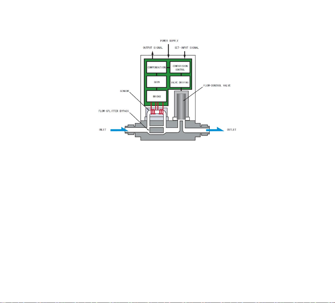
The S500 thermal mass flow controller is able to control gas mass flow rate within a large range in
real time accurately. Gas goes through a stainless steel capillary, to change the capillary
temperature distribution, resulting in upstream and downstream temperature difference, therefore
the flow rate can be measured. Unlike flow controllers or meters that measure gas pressure or
volume, this product’s accuracy won’t be affected by gas pressure or ambient temperature. The
electrical signal that represents upstream and downstream temperature difference is always a
real-time reflect of instantaneous flow rate. The PID circuit is used to control a proportional
solenoid valve constantly, thus control the flow rate precisely. It is particularly applicable for gas
precise measurement and control in control processes .
1.1 Range
The mass flow controller is widely used for flow measurement and control in the semiconductor,
vacuum coating, chemical, environmental and other industries.
1.2 Mass Flow Controller (Meter)
The mass flow controller (meter) is abbreviated as MFC (MFM). There are two functions in it: flow
measurement and control.
1.3 Features of S500 MFC (MFM)
☆High accuracy, fine linearity, small zero drift, fast gas flow response, small overshoot, and
so on.

2
☆Applicable to high pressure and vacuum. Small gas resistance, wide operating pressure range.
The measured flow rate won’t be effected by gas temperature and pressure.
☆All wetted parts have strong corrosion resistance. The valve body is made of stainless steel
(316L), and the gas-tight parts are made of fluorine rubber. The important parts, such as PCB, valve
body, spring and sensor, undergo strict factory inspection.
☆Can be mounted in any position.
☆Easy to use. It is easy to work together with an electrical or automatic control system. With
MT-52 or MT-51 series of Digital Readout and Control Unit, the instantaneous flow rate can be
measured and displayed accurately.
2. Terms
2.1 Mass Flow Rate
Mass flow rate is the flow rate that represents the mass of fluid flowing through a cross-section per
unit time. Gas mass flow rate is generally converted into volume/time in standard conditions. For
example: mL/min (SCCM industry standard), L/min (SLM industry standard).
Standard Condition: Gas Temperature: 273.15K (0℃);
Pressure: 101325Pa (1atm)

3
Table 2-1 Gas Mass Flow Rate Units
International Unit
Industry Unit
Gas Temperature
Pressure
mL/min
SCCM
0℃(273.15K)
101325Pa(1atm)
L/min
SLM
0℃(273.15K)
101325Pa(1atm)
mL/min
CCM
25℃(298.15K)
101325Pa(1atm)
L/min
LM
25℃(298.15K)
101325Pa(1atm)
2.2 F.S.
F.S. represents for full scale.
2.3 Accuracy
Full-scale accuracy: the ratio of the difference between controller indication and actual value
measured by a standard instrument to full scale (F.S). Such as: ± 1.0% F.S. (with suffix F.S.).
2.4 Calibration Conditions
Usually we we calibrate a MFC (MFM) on nitrogen (N2) in standard conditions. If a MFC (MFM)
is calibrated on other types of gas, the mass flow rate is a calculated result (volume/time) through
the conversion in standard conditions.
2.5 Response Time
When the set value step change (for example: from 0 to 100%) , the gas flow rate will follow the
change and reach a final stable value within a error range after a period of time, which is called
response time. T98 represents the specified time when the final stable flow rate equals to ± 2% F.S .

4
2.6 Operating Pressure Range and Pressure Resistance
Operating pressure range is the range of pressure difference between inlet and outlet. The MFC
(MFM) will work stably in the full range.
Pressure resistance is the maximum line pressure (gauge pressure) that a MFC (MFM) can tolerate
and will not leak.
2.7 Flow Direction
The direction of gas flows in the MFC (MFM).
Due to the structural characteristics of the thermal MFC (MFM), gas can only flow in the direction
that consistent with the arrow on the valve body and cannot flow opposite, otherwise the MFC
(MFM) will not work or even be damaged.
2.8 "Valve Override" Options
Impose a high level, for example +15VDC (take socket pin assignment as the criterion) in the
"valve override" pin, the valve will close.
When the "valve override" pin is vacant, the valve will be under control state. Valve opening can be
controlled according to the set value.
Impose a low level, for example -15VDC (take socket pin assignment as the criterion) in the "valve
override" pin, the valve will open.
The "Open" or "Close" command of S500 MFC (MFM) takes precedence over the implementation
of the set value, no matter what input set value is.

5
2.9 Auto Shut-off
When the set value is less than 1-2% of F.S., the valve will shut off automatically. Therefore, the
flow rate control range is from 2% F.S. to 100% F.S.
2.10 Auto-zero
Zero of MFC (MFM) may drift due to environment changes and prolonged use. In order to get a
higher flow control accuracy, the zero point should be corrected when necessary. The S500 MFC
(MFM) has a auto-zero function. When zero point changes, the MFC can automatically adjust it.
When the set value is less than 1-2% F.S., or apply +15V to the "Valve override" pin (“close” state),
and maintain the state for more than 4 minutes, the auto-zero circuit will work automatically.
2.11 Zero Temperature Compensation
The zero point may drift as ambient temperature changes. We will test the S500 MFC (MFM) zero
drift in different temperatures and compensate zero drift at the factory, in order to minimize the
effect of ambient temperature changes.

6
3. Principle
Figure 3-1 Principle of Thermal MFC
The MFC (MFM) consists of sensor, bypass channel, proportional valve, amplification control
circuit and so on.
The S500 MFC (MFM) works according to the effect of heat-conduction distribution, that flowing
fluid delivers heat to change the capillary wall temperature distribution, namely thermal profile
flow meter.
According to thermoelectric calorimetry, the mass flow rate will not be affected by gas temperature
and pressure. The flow signal measured by the sensor is amplified and compared with the presetting
voltage, and then the differential signal is amplified to control the valve. Through real-time flow

7
detection closed loop, the flow rate through the channel is equal to the set flow rate.
The bypass generates laminar flow between the main passage and the capillary wall, and makes the
detected voltage proportional to the flow rate through the channel.
The control valve used in the MFC is a proportional solenoid valve, and it will change the valve
opening according to the current applied on the electromagnetic coil.
The ±15V MFC (MFM) can be connected with MT-51 or MT-52 series of Digital Readout and
Control Unit generally. The functions of MT-51 and MT-52 are as follows: ± 15VDC power supply,
flow signal display, flow setting operating and so on. The MFC (MFM) and MT-51 or MT-52 are
connected with a cable.
4. Specifications
Table 4-1 S500 MFC Specifications
No.
Item
S500 MFC
1
Full Scale Flow Rate
(10,20,30,50,100,200,300,500) mL/min
(1,2,3,5,10,30) L/min
2
Valve Type
Solenoid valve
3
Valve Rest Position
Normally closed
4
Mounting Orientation
Free

8
No.
Item
S500 MFC
5
Flow Rate Control Range
2% - 100% F.S.
6
Flow Rate Measuring Range
0% - 100% F.S.
7
Response Time
1.5 Sec (T98) *
(2.5 Sec if F.S. ≤ 50mL/min)
8
Operating Temperature
5 - 45 ℃
9
Accuracy Guaranteed Temperature
15 - 35 ℃
10
Accuracy
±1.0% F.S.
11
Linearity
±0.5% F.S.
12
Repeatability
±0.2% F.S.
13
Operating Pressure Difference
10 mL/min - 5 L/min (50-300) kPa (D)
10 L/min - 30 L/min (100-300) kPa (D)
14
Pressure Resistance
3 MPa (G)
15
Leak Rate
1×10⁻⁸ Pa•m3/s (He)
16
Wetted Materials
316L, Fluorine rubber
17
Fittings
Swagelok: 1/4″Φ6 Φ10 VCR:1/4″3/8″

9
No.
Item
S500 MFC
18
Power Supply
±15 VDC (±5%)
+15 V ≤ 100 mA
-15 V ≤ 150 mA
19
Flow Rate Setting Signal
0 - 5 VDC
Input impedance > 2MΩ
20
Flow Rate Output Signal
0-5 VDC
Load output current capability ≤ 3mA
21
Electrical Connector
D - sub15
22
Weight (kg)
0.9
Order Specification:
When ordering, please specify whether it is a MFC or MFM, specify the product model, flow rate,
power supply and customized signal types as follows:
Please also specify flow rate, gas species, and fitting type.

10
For example: MFC (or MFM) - S500 AR111 (product model and signal type) ±15VDC 0-5V
500SCCM (flow rate) N2 (gas species) Φ6 (fitting type)
In the storage and transportation process, do not open the product packaging, and keep the product
way from rain, dust and bump.
Do not store the product in extremely cold/ hot or humid environment for a long time.
5. Installation and Connection
5.1 Installation Environment
The product is for indoor use, that operation temperature is 5-45℃and relative humidity is 60%
maximum.
The installation environment should be away from vibration, dust, electromagnetic interference,
and so on.
The product is required to use clean gas without water vapor and condensation. If a corrosive gas is
used, please specify the gas type when ordering.

11
5.2 External Dimensions
Figure 5-1 S500 Series MFC (MFM) Shape and Installation Dimensions

12
Table 5-1 Fittings and Dimensions
Fittings
L
W
T
H
D
4HM:1/4inch METRON SWL Fitting
127
76.2
29.8
102
12.7
4IS:1/4inch SWAGELOK Fitting
127
76.2
29.8
102
12.7
6MHM:Φ6mm METRON SWL Fitting
127
76.2
29.8
102
12.7
6MS:Φ6mm SWAGELOK Fitting
127
76.2
29.8
102
12.7
4CR:1/4inch VCR
124
76.2
29.8
102
12.7
Note: the height indicated in the figure does not include the cable plug.
5.3 Fittings
According to different needs, users can choose:
1. Swagelok: a. Φ6mm, b. Φ10mm, c. Φ1/4″, d. others.
Figure 5-2 Swagelok Connection

13
2. VCR: a. Φ1/4″, b. Φ3/8″.
Figure 5-3 VCR Connection
5.4 Circuit Connection
5.4.1 Electric Connectors’ Pin Assignment of ±15VDC Power Supply (D-sub15/Male)
Figure 5-4 Pin Assignment and Wiring Diagram of ±15VDC Power Supply (D-sub15/Male)

14
Table 5-2 Pin Assignment of ±15VDC Power Supply (D-sub15/Male)
Pin
Color
Function
1
Yellow
Signal COM
2
Orange
Flow Signal Output ( 0-5V OUT, load capability ≤ 3mA )
3
Brown
Not Connected
4
Not Connected
5
Red
+15V Power ( ≤ 100mA )
6
Green
-15V Power ( ≤ 150mA )
7
Not Connected
8
Blue
Set Signal Input ( 0-5V IN, input impedance > 1MΩ )
9
Black
Power COM
10
Purple
Signal COM
11
Not Connected
12
Not Connected
13
Gray
Valve override ( N.C.→ control, +15V → close, -15V → open )
14
White
Chassis ( Earth )
15
Not Connected

15
5.4.2 Electric Connectors’ Pin Assignment of ±15VDC Power Supply (D-sub15/Female)
Figure 5-5 Pin Assignment of ±15VDC Power supply (D-sub15/Female)
Table 5-3 Pin Assignment of ±15VDC Power supply (D-sub15/Female)
Pin
Color
Function
1
Not Connected
2
Not Connected
3
Black
Power COM
4
Blue
Set Signal Input ( 0-5V IN, Input impedance > 1MΩ )
5
Gray
Valve Override ( N.C.→ control, +15V → close, -15V → open )

16
Pin
Color
Function
6
Yellow
Signal COM
7
Orange
Flow Signal Output ( 0-5V OUT, Load capability ≤ 3mA )
8
White
Chassis ( Earth )
9
Not Connected
10
Brown
Not Connected
11
Green
-15V Power ( ≤ 150mA )
12
Green
-15V Power ( ≤ 150mA )
13
Brown
Not Connected
14
Purple
Signal COM
15
Red
+15V Power ( ≤ 100mA )
Note: At the power supply, two Signal COMs and one Power COM must be connected with
each other to ensure proper operations.
"Chassis" at 14 pin on a male socket and 8pin on a female socket are grounding lines that connect
to the metal base of flow meter by the in-house series-wound capacitance, and also should be
connected to the control cable shielding mesh to achieve shield. Users should take effective
measures to shield and separate the DC power, and thus prevent the interference signal getting into
MFC (MFM) system.

17
The " Chassis" and the "Power COM" should be connected directly with each other or through a
large capacitor to achieve point grounding (the existence of multiple ground should be avoided to
prevent the formation of ground loops). Thus zero and earth achieve equipotential, and this is also
one of the effective methods to resist interference.
6. Operation
The S500 MFC (MFM) needs to work coordinate with a Flow Display Instrument, computer or
PLC. When coordinate with MT-51 and MT-52 series Digital Readout and Control Unit, the S500
MFC (MFM) operating methods and steps are as follows:
6.1 Preparation before Power On
6.1.1 Connect the MFC(MFM) and the Flow Display Instrument using cable lines provided by our
company.
6.1.2 Choose the source of the setting signal. The signal source interface locates at the back plank
of the Flow Display Instrument. If the interface is connected with the Flow Display Instrument, we
can obtain the setting signal from the Flow Display Instrument. If we want to get the setting signal
from other equipment, the interface needs to connect with corresponding equipment. (For more
detail, please see Flow Display Instrument manuals)
6.1.3 Connect to gas circuit according to the direction indicated on the MFC (MFM) case. Please
ensure the pressure difference of inlet and outlet is within the working pressure range.

18
6.2 Power On
In order to ensure the accuracy of measurement, please warm up for 30 minutes before turning on
gas supply.
For example, when power is on, switch the valve override to "Close" and set the Flow Display
Instrument to zero. When the zero is stable, transfer to "Control", and then adjust flow rate, so that
actual flow rate will track and change with the set value.
6.3 Open and Close
When switch to the “open” state, the valve opening will be maximum. If there exists pressure
difference between upstream and downstream, there will be a lot of gas going through the pipeline.
“Open” function can be used to purge or clean residual gas in the pipeline.
After purging, the MFC should be switched to "Close" before normal "Control" operation can be
carried out. The "Control" state cannot be directly transferred to, because thus it will not guarantee
the normal valve control function.
When switch to "Close" state, the valve will shut off, and no gas will flow through the MFC.
6.4 Valve Control
When switch to “control” state, users could control gas flow rate by changing the set value.
6.5 External Valve Override
“Valve override” connects to + 15V high level can make valve “close”;
“Valve override” connects to - 15V low level can make valve “open”;
Table of contents
Popular Controllers manuals by other brands

Mitsubishi Electric
Mitsubishi Electric GB-24A Instruction book

TouchWand
TouchWand ACWand installation manual

Comunello
Comunello RAYWIN instruction manual

Honeywell
Honeywell CIPer 30 installation instructions

IFM
IFM ecomatController CR0708 operating instructions

TAC
TAC Forta M310/800 installation instructions