Horizon Fitness HD-S2 User manual

Horizon Global Electronics Ltd.
Unit 3, West Side
Flex Meadow
Harlow, Essex
CM19 5SR
Phone: +44(0) 1279 417005
Fax: +44(0) 1279 417025
© Copyright 2009, Horizon Global Electronics Ltd. No part of this document may be copied or reproduced without the written consent of
Horizon Global Electronics Ltd. Unit 3, West Side, Flex Meadow, Harlow, Essex CM19 5SR
Horizon part number. KM137/1.0
DVB-S – DVB-S2 – QPSK – DSS
MENU
OUT
INPUT
HORIZON DIGITAL SATELLITE METER
ON
OFF
HD-S2

Contents
Contents Page 1
Safety Page 2
Your Meter Page 3
Accssories Page 4
Battery Charging Page 5
Using Your Meter Page 6
Setup Menu Page 7
HD-S2 Sub Menu Page 8
Sub Menu Overview Page 8
DiSEqC Page 9
Spectrum Display Page 10
Constellation Page 11
Customize Page 12
Data Logging Page 14
21 Volt Supply / SCR Output Test Page 15
Histogram Function Page 15
SCR Dual Display / LNB Drift Page 16
LNB/Cable Test Page 16
Orientation Page 17
USB Driver Installation Page 18
Downloads Page 20
Transferring Data Page 22
FAQ Page 23
Specifications Page 24
Notes Page 25
Manufacturer’s Statements Rear cover
Thank you for choosing to buy the HD-S2 satellite meter. Please read through the instructions carefully
before using your meter to familiarize yourself with all of the features available.
The HD-S2 is a compact, lightweight and easy to use satellite installation meter featuring an easy to read
display that shows signal strength and digital signal quality. Finding your satellite is easy: use the left or
right arrow keys to scroll through the selections, and your HD-S2 will lock onto the satellite shown in the
display when it is in range. Everything you need is supplied with your meter, which includes a A/C charger
lead, in-car charger and USB lead. The rain cover and carry case are already fitted.
Spare Li-Po (Lithium-Polymer) battery packs are available directly from Horizon Global Electronics and
authorised distributors, Batteries can be replaced without voiding your warranty. Replacement carry cases,
rain covers, USB leads, A/C charging leads and in-car chargers are also available directly from Horizon
Global Electronics Ltd. or an authorised distributor.
Page 1

Safety
Page 2
• WARNING! This device is capable of generating 21 Volts.
• Do NOT expose this meter to rain or moisture!
• Clean only with a soft dry cloth.
• Always use the protective case and cover provided.
• Read the instructions carefully before operating your unit for the first time.
• Care should be exercised when using the carry strap as it can present a
choking hazard; only use when slipping or falling is not a possibility.
• Do not disassemble your unit or interfere with the internal components;
this will void your warranty and there is a possibility of electric shock.
“If the equipment is used in a manner not specified by the manufacturer, the protection provided by the
equipment may be impaired”.
• Only use the provided battery, AC charger lead and DC car charger lead provided, as using
other types may cause damage to your unit, which will void your warranty and may cause electric
shock. Replacement charging leads and battery packs are available directly from Horizon Global
Electronics Ltd.
Li-Po battery notes:
A damaged battery represents a hazard and should be replaced. Always replace
damaged battery packs with the correct type – never attempt to repair them.
Do not short-circuit the battery terminals
Do not dispose of in fire
Do not disassemble
Remember:
This symbol is intended to alert users of possible hazard or damage in operating this unit.

Your Meter
Page 3
USB
Input
DC Charge
Input 12V DC
1.5A
AC Charge Input
100 – 240 V ~
0.8A Max
50/60 Hz
Serial number
Battery cover
Only use Horizon Li-Po
(Lithium Polymer) battery
packs (fitted).
Tamper proof
warranty seal
Keypad
LNB Input
1.5A
Warning Serial Number: xxxxxxxxxxx
SHOCK HAZARD – DO NOT OPEN TO
PREVENT SHOCK DO NOT REMOVE
COVER NO SERVICEABLE PARTS
INSIDE DO NOT EXPOSE TO RAIN OR
MOISTURE!
DC blocked output

Accessories
Page 4
Your HD-S2 is supplied with this Instruction Manual and these items below. Please check if you have all the
following. If any items are missing please contact your supplier.
Only manufacturer’s replacement parts should be
used, otherwise safety of the meter may be impaired
DC Car Charger Lead
Fitted with 2 Amp Fuse
(AW992CIG)
AC Charger Lead (AW993UKP/EUR)
Rain Cover (ARHDBDU)
(should be fitted at all times)
USB Lead (AW998USB)
Li-Po Battery Pack (BP1524)
Carry case (AL006BK)
Note: The items shown above are subject to change without notice.
Quick Start Insert
HD-S2

Battery Charging
Page 5
The meter will NOT be fully charged when you receive it. We recommend you charge it for an initial 8 hours
before use. If your meter is not being used for a long period of time, we recommend disconnecting the battery.
You can also top up your battery from your vehicle with the in car DC Adapter supplied. You should top up the
charge every 2 weeks. The battery pack is replaceable, but it should only be removed or disconnected in the
event of a failure. Please see page 25 for battery removal.
On the bottom of the case there is a small velcro
flap which covers the AC input for charging.
Charging with the AC lead
Charging from a vehicle
The vehicle 12V DC charge port is on the right side of the unit.
Plug the car charger lead into the bottom socket and the other end
to the vehicle’s “aux” socket. Please note that on certain vehicles the
aux socket is switched off unless the vehicle is running.
For in-vehicle charging only use the lead supplied. The use of another lead may damage the meter and will void
the warranty. The HD-S2 can remain connected to either power source in “Trickle” charge state for an extended
period of time. Once “Charge Complete” appears on the display the HD-S2 will be in a trickle charge state.
1.5A
Note: The meter will not operate while the unit is being charged.
Note: When charging your battery HD-S2 Li-Po battery please ensure that the ambient temperature is above
freezing point 0º C (32º F) and not above 40º C (100º F) this will prevent damage to your battery pack.
Note: Do not charge from a vehicle with a
higher battery voltage or positive ground!
The Li-Po battery pack is replaceable. Always handle the battery with care avoiding shock or impact.
Remove the HD-S2 from its carry case, and on the underside of the meter release the two catches and detach
the battery door. Press the battery down at the end closest to the connector (this will cause the battery
to pop up at the bottom). Now cover the battery with your hand and turn the meter over so that you catch the
battery. Carefully detach the battery connector. You can now fit your replacement battery in the reverse order
of removal.
Note: Avoid pulling the battery cable as it is short to ensure a snug fit.

Using Your Meter
Page 6
ON
OFF
The HD-S2 keypad. All of the meter functions are accessed from here.
To turn the meter on press the button once and the Horizon animation will appear.
The next screen will display the meter information, including
model, version, satellite list selected and battery percentage.
Note: Satellites shown will be from the last used list.
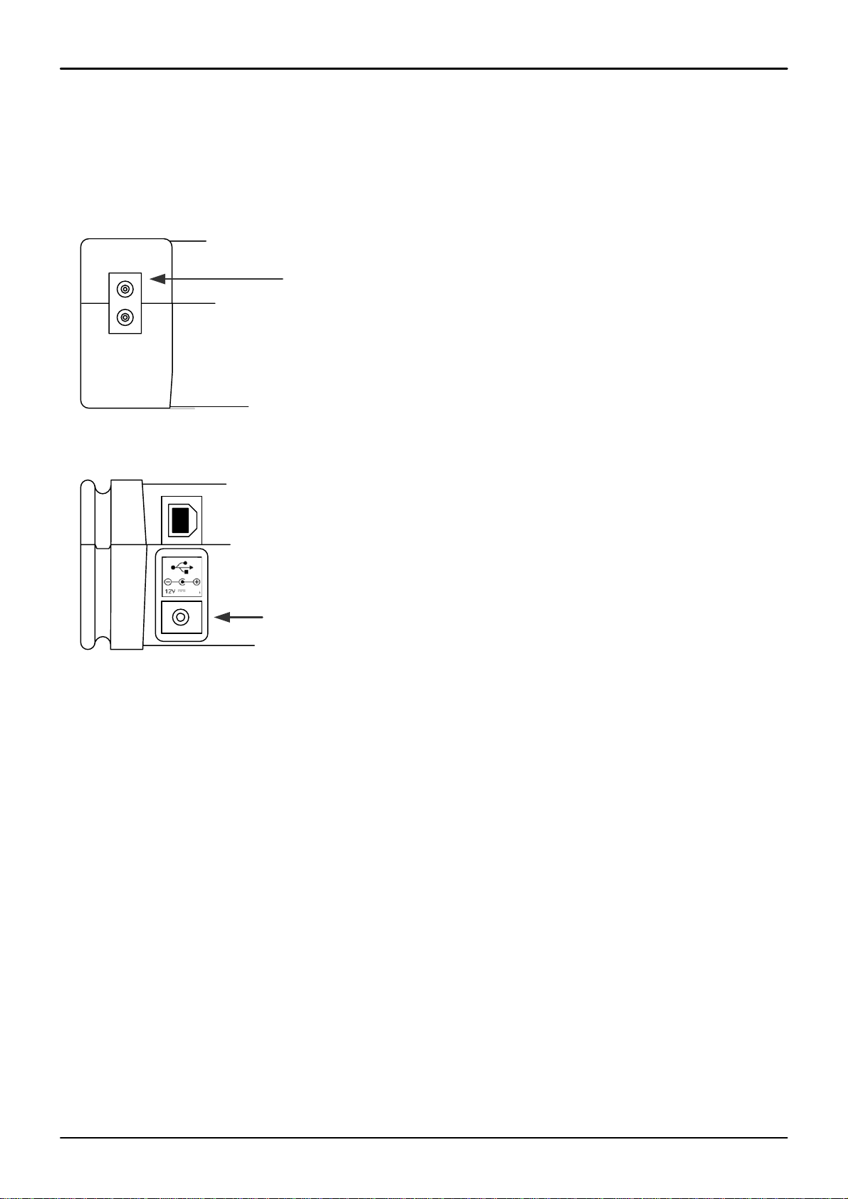
Once your dish mounting has been securely installed in a suitable direction
connect the LNB to your HD-S2 meter with a short length of cable (1.5m or 4 feet
being ideal): note that this cable is not supplied – you should use a high quality
satellite cable.
Tip: Your dish clamp should be just nipping the metal work allowing you to adjust
the dish position, and it should hold when you release.
Use the LEFT or RIGHT arrow keys to cycle through
the selections available until the desired one is shown.
Point the dish in the approximate direction of the required satellite,
and slowly sweep the dish across the sky, adjusting your elevation at
the end of each sweep. While you are sweeping the sky the rate of
beeps will change as you pass each satellite; the scale on the meter
will also change. If very low RF levels are found the dBuV value will
show << dBuV. For extremely high levels >> dBuV will show.
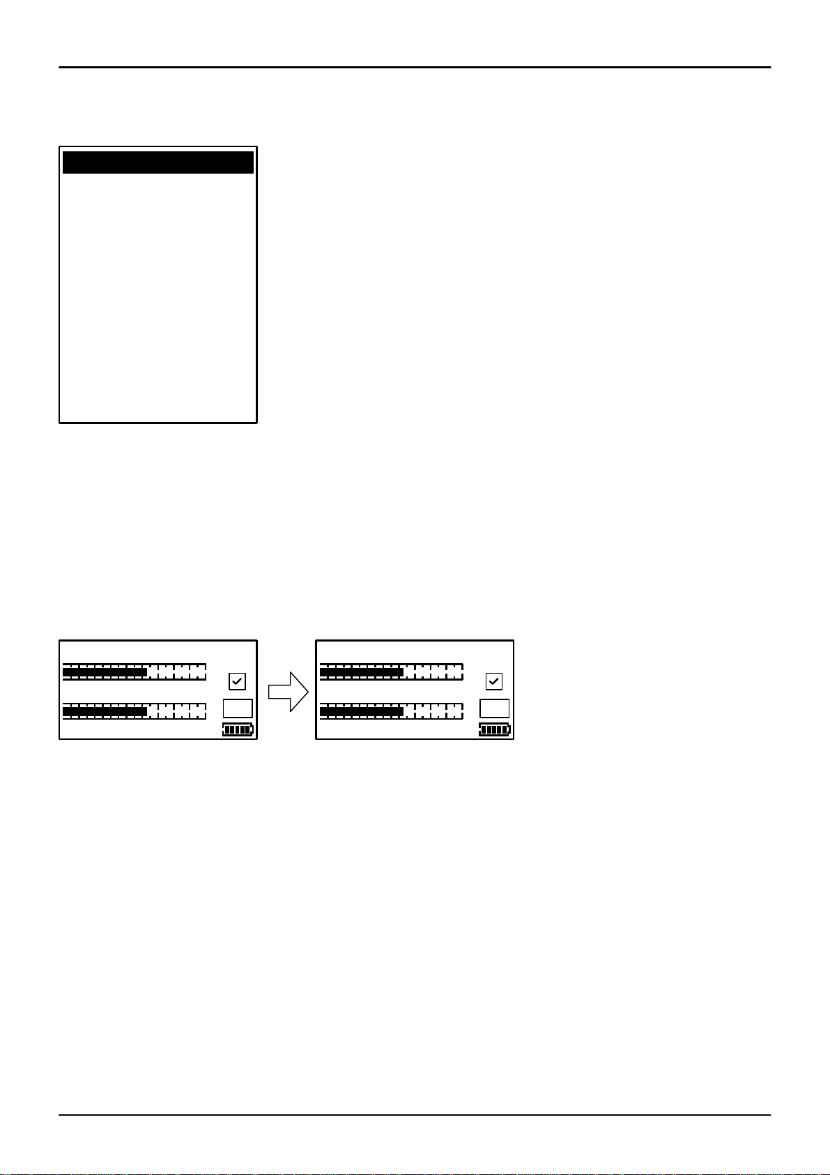
Once a lock has been acquired the second bar that is referencing
MER is shown and this is directly relative to the quality of the signal.
The padlock symbol is also shown locked confirming the signal lock.
You can now use both of this displayed measurements to peak the
antenna (ideally getting these levels as high as they will go).
Now that you have acquired a good lock you can further tweak the
pointing of your antenna to maximise the satellite system performance
by pressing the On button once to access the RF and MER magnified
display. This will provide you with a sensitive linear scale allowing you
to make very fine adjustments.
ON
HDSM-USB S2
(c) 2009 V1. 0A
Astro Malaysia
Battery 32%
Searching
RF 68.0dBuV
U
VL Measat3 tp1
RF 66.8dBuV
U
VL Measat3 tp1
MER 13.9dB
RF 167
U
VL Measat3 tp1
MER 72
RF 66.8dBuV
U
S2 Measat3a tp14
MER 13.9dB S2
Shown on the right is a lock acquired on a DVB-S2 service the padlock
symbol is showing locked condition and there is also an additional
indication that the signal acquired is DVB-S2.
l
l
l
RF 66.8dBuV
U
S2 Measat3a tp14
DER= 6.00E-8 S2
l
x
RF 66.8dBuV
U
BER= 6.00E-8
l
VL Measat3 tp1
Pressing the On button
again will also show the
BER Bit Error Rate for
DVB-S1 carriers this is
shown as a numerical
value.
For DVB-S2
carriers DER is
shown indicating
a Derived Error
Rate.

Setup Menu
Page 7
To access the Setup Menu ensure your HD-S2 is off and press the UP (off) button once.
The following options are available from this menu.
By using the keypad as cursor keys you can navigate
through the set up menu using UP and DOWN, and
change values by using LEFT and RIGHT keys. Once
you have made your selections return to the top of the
menu highlighting Exit and press the left or right key to
apply the changes and switch the meter off.
You can also go back to the default setup by selecting
Defaults. This operation will not affect any of the
satellite settings stored in memory.
Note: The full menu is shown here, whereas only four
options are visible at any one time on the LCD display.
The HD-S2 has the following languages available English and Malaysian, the default is English.
LNB Voltage: This feature enables you to switch the LNB supply voltage off. While the LNB Voltage is set
to 0 Volts the Satellite name on the top line of the display will alternate with “LNB 0V” to indicate that no
LNB voltage is applied. This selection will remain active until it has been changed back to LNB 13V/18V
even if the meter is switched off. Only set LNB Voltage to 0V if the LNB is being externally powered (see
LNB/Cable Test).
Note: While the LNB Voltage has been selected as 0V then the satellite
name on top line of the display will alternate as illustrated above.
The Azimuth option allows you to select either True (relative to true North) or Mag (with magnetic offset
applied). This option affects how the Orientation display is shown. See page 16 for more information.
Using the Defaults option will set your meter back to its default settings, the satellites stored
in memory will remain unaffected including your custom carrier selections previously stored.
The version number information at the bottom of the Setup Menu “1. 0Aa-0002”
has no function other than to inform you which version of firmware is in use.
The Malaysia V1. 0 indicates the version of regional look up table currently
loaded (in this instance Malaysian cities).
Backlight on
Clicking on
Brightness 10
Contrast 20
Sleep 6M
English
RF dBuV
LNB 13/18V
Defaults
Azimuth Mag
1. 0Aa-0002
Malaysia V1. 0
The RF level measurement can be displayed as one of the following values dBuV, dBm or dBmV
RF 66.8dBuV
U
S2 Measat3a tp14
MER 13.9dB S2
lRF 66.8dBuV
U
LNB 0V
MER 13.9dB S2
l
Exit

HD-S2 Sub Menu
Your HD-S2 has a range of features available from the Sub Menu.
To access the sub menu press the UP (off) button once from the
searching screen. Using the keypad as cursor keys you can select the
various options. At any time you can press and hold the UP button to
switch the meter off. When Exit is highlighted, you can also use the
RIGHT button to switch the meter off.
Page 8
Note: The Constellation. Log, LNB 21V, Log As 00000, Log All 00000
and LNB Drift functions are only available once a satellite has been
found and a lock acquired.
DiSEqC
Spectrum
Spectrum
Constellation
Custom
Customize
LNB 21V
Orientation
Log as 00000
Log All 00000
LNB Drift
LNB/Cable test
◄Exit ►
The full sub menu is shown on the left, only 4 selections visible, you
may need to scroll up and down to access the function you require.
Sub Menu Overview
DiSEqC: Allows the sending of DiSEqC switch commands to select different LNB sources.
Spectrum: Shows you a visual representation of the selected transponder.
Spectrum Lifts the signal amplitude so that weaker signals can be seen.
Constellation: Shows a constellation diagram of the current locked transponder selection.
Custom: A list of editable transponders (carriers) stored on your meter.
Customize: The function allows you to edit the custom carriers.
LNB 21V: To enable 21 Volts for Stacked LNB assemblies.
Orientation: An aid to finding your satellite quickly that provides look angles.
Log as 00000: A logging function for individual transponder measurements stored incrementally.
Log All 00000: A logging function for all transponders associated with the satellite selected.
LNB Drift: A measurement tool for testing LNB frequency drift relative to transponder centre frequency.
LNB/Cable Test: Performs a LNB function test and displays voltage and current measurement.
:

DiSEqC
The following DiSEqC switch functions are available from the sub menu of the HD-S2 meter.
►DiSEqC
From the sub menu DiSEqC function shown here you can select a variety
of DiSEqC switch commands to suit the needs of your installation. Press
the right arrow button to access the the different options available. Once
a DiSEqC command has been selected with the right arrow key the
command will be sent and you will be returned to the last satellite
selected.
Page 9
The 4 Position Switch option gives
you the selections of A,B,C and D
and these selections can be used
with a conventional 4 way DiSEqC
switch. Selecting Exit here will
take you back to the sub menu.
The Options selection
enables you to send Tone
Burst commands (A or B).
Selecting Exit here will take
you back to the sub menu.
The Dual Horn option is for use with
dual feed LNB assemblies enabling
you to select the band and polarisation
available individually. Selecting Exit
here will take you back to the sub
menu.
The following selections are available from the Dual Horn menu.
Satellite A Vertical Low Satellite A Horizontal Low Satellite B Vertical Low Satellite B Horizontal Low
Satellite A Vertical High Satellite A Horizontal High Satellite B Vertical High Satellite B Horizontal High
For SMATV switch systems the following DiSEqC command options are available.
The SMATV switch option is for
use with systems with up to 16
inputs. Selecting Exit here will
take you back to the sub menu.
▼For more
Exit
Spectrum
Spectrum
►4 Pos Switch
Exit
Options
Dual Horn
SMATV switch
►Options
Exit
4 Pos Switch
Dual Horn
SMATV switch
►Dual Horn
Exit
4 Pos Switch
Options
SMATV switch
◄Exit
LNB A
LNB B
LNB C
LNB D
▼For more
◄Exit
Option A
Option B
◄Exit
SAT A_Ver_Low
SAT A_Ver_High
SAT A_ Hor_Low
►SMATV Switch
Exit
4 Pos Switch
Options
Dual Horn
▼For more
◄Exit
SMATV switch 1
SMATV switch 2
SMATV switch 3

Page 10
Spectrum mode is available from the Sub-menu (press the UP arrow while the signal level or carrier/noise
display is on screen). Scroll down to highlight “Spectrum”, and press the RIGHT arrow. The screen will change
to display the spectrum.
The graphic will be centred on the frequency of the selected transponder: in our example of a Low Band setting,
the display is centred on 11840MHz. The span (range of frequencies displayed on screen) is set by default to
240MHz; which gives a display of 8 adjacent carriers at 30MHz spacing. By pressing the DOWN button, you can
cycle through a range of spans from 60MHz (to zoom in on one carrier in particular) to 1200MHz.
Centre the chosen frequency on the display by pressing the LEFT and RIGHT buttons. Note that you will not be
able to go beyond the limits for each band, which are indicated by arrows pointing right (lowest frequency) or left
(highest). Note that the Low Band coverage extends from 10700MHz to 11600Mhz, and the High Band from
11550MHz to 12750MHz, so there is some overlap between the Low and High Band for Universal LNB’s.
RF level is shown by a solid band at each sampled frequency (see image). There will be areas of low-level
signal between the carriers, and the bigger the distance between peaks and valleys, the better the carrier-to-
noise ratio. Good C/N ratio is important for trouble-free reception!
The top line of the screen alternates between “Centre” plus the selected frequency (shown at the dotted vertical
line in the centre of the display) and “Span” plus the frequency span in MHz. In “Span” view, the polarization of
the carrier (H)orizontal or (V)ertical is shown. If High Band is in use, and 22KHz is enabled, the tone symbol
will appear next to the Polarity.
►
►
►
►
The Spectrum information bar at the top of this screen will alternate between the current frequency, span and RF.
Note: You can exit spectrum mode at any time by pressing the UP button once. This will return you to the
searching screen on the selection that you made previously.
Tip: If you have defined a custom carrier you can view it in spectrum mode too (see Customize on page 12).
In low signal level conditions use the ►Spectrum may be seen.
VSpan 240MHz
►
►
►
►
Centre 11576MHz
►
►
►
►
RF 60.7dBuV
Spectrum Display

Constellation
Provided the meter is locked to a DVB-S QPSK, DVB-S2 QPSK / 8PSK / APSK or DSS modulated carrier
the constellation mode is available from the Sub-menu (press the UP button while the signal level or carrier/
noise display is on screen). If there is no lock, the option will be “greyed out”. This type of diagram is almost
meaningless when it cannot display formatted data – as dots would appear randomly in each quadrant, and
there would be no visible pattern.
In the Sub-menu, scroll down to highlight “Constellation”, and press the RIGHT arrow. The screen will
change to the QPSK constellation display and a listing of the current transponder settings.
The graphic displays the 4 quadrants of a QPSK signal. A “good” display will show a cluster of dots centred
in each quadrant. The more concentrated the cluster, the better the quality of the received signal; dots
“straying” from the cluster indicate noise on the signal, phase errors, and other unwanted artefacts.
The aim is to achieve the best result possible, which a thorough alignment of the LNB should achieve. With
the constellation diagram, you get reassurance that the adjustments have been done well.
At the right side of the screen is a list of the parameters for the currently chosen transponder:
Frequency in MHz: this is the measured frequency after “pull-in” by the meter’s Automatic Frequency Control
(AFC), so the displayed value may differ slightly from the nominated value in the configuration file;
Symbol Rate in kilo Baud (Kilo Symbols / Second): the data rate is critical in identifying and locking to the
selected carrier;
FEC (forward error correction) value: data on the selected carrier will conform to one of a short list of
standard FEC values;
IQ Norm indicates that IQ Swap is not present. Pilots are shown if present.
Tip: The constellation diagram can be used down stream from the LNB to trace problems caused by faulty
components that introduce noise and affect the quality of the digital signal.
11840MHz
22000kBd
QPSK 5/6
IQ Norm
Page 11
This illustration shows how a typical
QPSK constellation diagram would
be represented.
10758MHz
30000kBd
8PSK 2/3
IQ Norm
Pilots
This illustration shows how a typical
8PSK constellation diagram would
be represented.
10750MHz
30000kBd
16AP 2/3
IQ Norm
Pilots
This illustration shows how a typical
16APSK constellation diagram
would be represented.
32APSK Constellation display is also supported.

Customize
You can set the desired frequency by using the UP and DOWN arrow
keys to change the highlighted number and LEFT and RIGHT to step to
the next one. Once you have your desired frequency, press the right
arrow to step on to the Symbol Rate screen. Note: You will not be able
to select out-of-range values relative to the local oscillator. If you try to
enter a number that is out of range, the meter will beep, and the
number will not change. You may need to step left or right to adjust the
value in the next column before stepping back to the current digit.
In much the same manner that you defined the frequency, set the
Symbol Rate to match the wanted signal: highlight the numbers with the
LEFT or RIGHT key and change the value with the UP and DOWN
arrow keys. Symbol rates from 01000 to 45000 can be set. Once you
have the desired symbol rate press the RIGHT arrow to step on to the
FEC screen. The same applies here to values that are out of range –
you may get a beep and a refusal to change the current digit.
From this screen we can select the desired FEC. If the FEC is unknown
then select Unknown and the HD-S2 will try them all when searching
from the Custom Carrier. Use the up and down keys to cycle through
FEC options. Press the RIGHT arrow to step on to the LNB voltage
screen. See FEC Notes for more information on the next page.
Note: If you are using a block type LNB for VSAT installation, 18 Volts
is typically selected to power this kind of LNB, as the polarization is
manually adjusted. Consult your LNB documentation for its operational
requirements.
Continued...
To edit the selections available from the custom carrier list select Custom and the selection you wish to edit
then select Customize from the Sub Menu. You can now edit your chosen custom carrier to what you require.
In this example we have chosen to edit “Custom DVB 1". Select your
local oscillator first by using the UP and DOWN keys. Various local
oscillators are available and some have 22KHz tone available also.
Once you have chosen the require local oscillator press the right arrow
button to set your frequency.
Page 12
There are 6 default custom carriers available that you can choose to edit which are illustrated in the table below.
DVB-S1, DVB-S2, and DSS are supported. These default carriers can also be reconfigured from the HD-S2
support web site via www.horizonhge.com
Custom DVB-S1 1 Custom DVB-S2 1 Custom DSS 1
Custom DVB-S1 2 Custom DVB-S2 2 Custom DSS 2
On this screen we can select the LNB voltage: 0, 13 and 18 volts. Press
the RIGHT arrow button to step on to the IQ screen.
Searching
RF 68.0dBuV
U
LNB 9.75 ▲▼
l
Searching
RF 68.0dBuV
U
Carrier 0758MHz
l
1
Searching
RF 68.0dBuV
U
Symb 2000kBd
l
2
Searching
RF 68.0dBuV
U
FEC 3/4
l
Searching
RF 68.0dBuV
U
LNB 13V
l

Customize
Page 13
By pressing the DOWN arrow on this screen all of the values you
have set will be discarded and the meter will return to searching
mode on the last satellite selected before entering Custom Carrier
mode. Alternatively, use the RIGHT button to cycle through the
custom carrier options to change your settings.
Tip: Common carrier configurations can result in a multiple lock situation. For
example, carriers that have an FEC of 3/4 and a Symbol Rate of 27500 may
lock on multiple satellites. Where possible, look for unique Symbol Rates that
are unlikely to be duplicated on other satellites at the defined frequency.
Here you can select IQ un-swapped (Norm) or swapped. Sometimes
IQ Swap is required to obtain a lock but for most of the time this is left
selected to Norm (Normal). Use the Swap selections if you failed to obtain
a lock so far. There are three IQ options available Norm, Auto and Swap.
Use the Up and Down Arrow keys to select. Press the right arrow
key to step onto the Save and Exit screen once you have made your
selection. Note: IQ Swap is mostly applied to C-Band services.
FEC Notes
Once you have selected the custom carrier options the following FEC’s and
modulation schemes are available. It is also possible to select “Unknown” so
that the HD-S2 will scan the available FEC’s relative to the custom carrier type.
DVB-S1 DVB-S2 DSS
1/2
2/3
3/4
5/6
6/7
7/8
1/2
2/3
3/4
5/6
6/7
7/8
QPSK 1/4
QPSK 1/3
QPSK 2/5
QPSK 1/2
QPSK 3/5
QPSK 2/3
QPSK 3/4
QPSK 4/5
QPSK 5/6
QPSK 8/9
QPSK 9/10
8PSK 3/5
8PSK 2/3
8PSK 3/4
8PSK 5/6
8PSK 8/9
8PSK 9/10
16APSK 2/3
16APSK 3/4
16APSK 4/5
16APSK 5/6
16APSK 8/9
16APSK 9/10
32APSK 3/4
32APSK 4/5
32APSK 5/6
32APSK 8/9
32APSK 9/10
Pressing the down arrow key here will apply your changes to the custom
carrier slot that you have just edited. Pressing the left arrow button will
enable you to go back and make changes before saving if required.
9.75
10.6 +22KHz Tone
10.0
10.25
10.5
10.7
10.7 +22KHz Tone
10.75
10.75 +22KHz Tone
11.25
11.25 +22KHz Tone
11.3
11.3 +22KHz Tone
17.25
18.25
18.75
19.25
19.75
21.0
5.15 C-Band
5.76 C-Band
5.95 C-Band
Ku-Band
LNB Local Oscillators: (GHz)
C-Band Ka-Band
Searching
RF 68.0dBuV
U
IQ Norm
l
Searching
RF 68.0dBuV
U
Save and Exit ▼
l
Searching
RF 68.0dBuV
U
Discard ▼
l
Pilot mode (DVB-S2 Only)
Searching
RF 68.0dBuV
U
Pilots Auto
l
For DVB-S2 one more additional step is required. Pilots, Pilot Auto and
No Pilots is a function that is only enabled when creating a DVB-S2
custom carrier, where you are uncertain if Pilots are required or not
select Pilots Auto.

Data Logging
Before using the logging function acquire the satellite that you have chosen, ensuring that the received levels are as
good as they can be. Then access the Sub-menu by pressing the UP button once; navigate down and highlight the
“Log as 00000" line. By pressing the right arrow at this point the levels from your satellite selection will be stored in
to the memory and numbered; this number will increment each time your store your measurements. Note this
number down as you will need to refer to it later when downloading the log information from your meter later.
The logging software required to extract the stored values is available from the www.horizonhge.com web site.
Note: Before you start to use the logging program please ensure that the USB drivers have already been
downloaded as described on pages 18 and 19.
To start the Log Reader program double
click the HD-S2 Log Reader program icon
(this will look like a target) a small program
will appear as illustrated.
Connect your HD-S2 via the USB lead supplied
to you PC. Wait for the HD-S2 to settle in
Program mode and then click Read.
Once the file has been read a pop up
will appear “Log download complete”
Once you click OK you will be presented with a table of your logged measurements. From here you
can export this data in CSV (Comma Separated Values) format for use with other office programs.
Tip: If you wish to erase the current log data within the
HD-S2 select the File drop-down menu and click on Erase Log.
Remember: When you erase the meter log data the log counter
on the meter will not be reset but the stored values will be cleared.
Page 14

21 Volt supply
Future SCR systems are supported and can be installed using selections downloaded from the
www.horizonhge.com web site. This will allow you to perform an installation even if the SCR is
part of the LNB assembly. SCR selections will be clearly labelled on the HD-S2 download web page.
SCR Output Test
For the Future a Single Cable Router output can be quickly checked at the outlet plates of a distribution system
using a new feature only available on the HD-S2. The SCR selection should be used to verify the presence of the
required services after the antenna installation has been completed.
Histogram Function
1 2 3 4 5 6 7 8
The illustration on the left shows the results found at the distribution
points. In this case 8 simultaneous measurements in real time have
been made. These 8 measurements reference the SCR translated
output frequencies. This quick and easy check tells us that the satellite
set top box should function fine as all of the services are available.
The Histogram function is also available for download as a
setting in the future from the www.horizonhge.com web site.
The SCR takes the satellite inputs and arranges them into a single
continuous extended band. The Histogram displays the presence of
these rearranged frequencies.
In this example the 8 frequencies are spaced at regular intervals across L-Band (950 to 2150 MHz).
Some SCR LNB assemblies require the 21 Volt option available from the HD-S2 sub menu.
The 21 Volt option is only enabled for Dual SCR and Histogram selections.
Note: To access the sub menu from the Dual SCR setting press the off button once and use
the down arrow key to navigate to “►LNB 21V”. You will be asked “Are you sure?”; press the
right arrow button again, and the 21 Volts will be applied.
The Histogram function also features a easy to use Pass / Fail
indicator. Pressing the On button will switch to the Pass / Fail
indicator as indicated on the left.
Failures can indicate that an existing cable run may not be suitable for re-use, or that investigation of connections
is required.
Page 15
If the levels fail to reach the required
level for a pass then this is indicated
by levels under the pass line and a
fail on the second display as shown.
Histogram
Histogram
1 2 3 4 5 6 7 8
PASS
FAIL
OK
Histogram
1 2 3 4 5 6 7 8
PASS
FAIL
OK
1 2 3 4 5 6 7 8
Histogram Histogram
1 2 3 4 5 6 7 8
PASS
FAIL
X
Please note: The Dual and Histogram SCR features are optional downloads that are not available at this time.

SCR Dual Display
The HD-S2 has a SCR dual display capability which will be enabled by settings released to
the HD-S2 download web site at a later date.
As manufacturers will be releasing various combinations of SCR LNB assemblies, downloads
suitable for these requirements will be made available via the www.horizonhge.com web site.
LNB/Cable Test
The LNB / Cable test is a quick function to check for possible fault conditions and will indicate if there is a problem.
LNB / Cable OK
LNB Fault
LNB / Cable Fault
The test results will appear after a few
seconds as indicated in the table below.
Note: The above function is for indicative purposes only and will not be suitable for SCR (Single Cable
Router) type systems. This feature tests for an open or short circuit in the cable or LNB and checks RF level
with the LNB powered and not powered. It may not indicate ‘Fault’ if a problem is otherwise related.
Page 16
Additional feature:
If power is applied externally to the LNB then the LNB / Cable test will
not go ahead. Instead, the voltage on the line is displayed on screen.
LNB Drift
VL Measat3 tp1
Min +0.880
Max +0882
Drift +0.880MHz
The LNB drift function illustrated on the left here will indicate how much the
LNB Local Oscillator is offset against the calculated center ferquency after
down-conversion to L-Band. Excessive drift (greater than 3 MHz would
indicate that there could be a problem with the LNB in use.
LNB / Cable test
Please wait...
◄Exit

Orientation
Page 17
To assist you with your satellite installations, an orientation function is available so that you can obtain azimuth,
elevation and skew (polarisation) angles for your antenna alignment from a major town or city that is close to
your installation site. This will save you time when looking to acquire the satellite you have chosen (in this
example Hotbird at 13º east).
►Orientation
▲▼For more
Once you have chosen the satellite you wish to find, enter the sub menu
by pressing the Off button once. Then navigate down with the On button
until the option is highlighted. Press the right arrow
button to select this function.
►Orientation
When you select Orientation, the last location set will be shown again
(in this example it was London, UK). There is the option to continue to the
Azimuth, Elevation and Skew values for this location or change city or the
country. The HD-S2 has the majority of Malaysian cities pre-loaded ready
for use and these lists can be updated via the www.horizonhge.com web
site in the future.
Ampang
Azimuth Mag 252.4
Elevation +77.3
Skew (A) + 71.9
Skew (B) + 18.1
If we selected the option to continue, the look angles for Hotbird from
London would have been displayed. The skew has 2 values (A / B)
where the polarisation (skew) scale on the back of some antennas
has been offset by 90º. Note: The azimuth angle can be set to Mag
(magnetic) to match your compass (relative to magnetic north) or
True relative to true north from the setup menu.
◄Back Select►
J
A
P
K
We can now proceed to select a city within Malaysia by using the Change city option and in this example we will
chose Kuala Lumpur.
Select city
Press the right arrow button to continue until you have reached your required city (you can also navigate to other
locations within the selected country from here by alphabetical order). There is also a step back feature so that
you can change your selection. Once you have selected your city the look angles will be displayed. Press any key
on the look angle display to return to your satellite selection.
Custom List
Customize
LNB 21V
►Continue
Ampang
Malaysia
Change city
◄Back Select►
J
A
P
Ku
Select city
◄Back Select►
J
A
P
Kua
Select city
◄Back Select►
J
A
P
Kuala Lumpur
Select city
Kuala Lumpur
Azimuth Mag 253.1
Elevation +77.5
Skew (A) + 72.6
Skew (B) + 17.4

USB Driver Installation
1) Connect the meter for the first time to a PC equipped with
USB port(s), If the USB drivers don’t automatically load,
then the “Found New Hardware Wizard” will appear.
Then click “Next”
2)
Select “Install the software automatically”
Then click “Next”
3)
4)
While your PC is searching for the
drivers a window like this will
appear.
The first stage of the driver installation is now
complete; your computer will now proceed to
download the additional driver required.
Click the “Finish” Button.
Page 18
Ensure your PC has access to the internet before you proceed.
Select “Yes, this time only”.
Continued...

USB Driver Installation
Page 19
Continued...
5)
To complete the installation of the new additional
driver for the USB Serial Port, click the “Next”
Button.
6) While your PC is searching for the drivers, a
window like this will appear.
7) The HD-S2 driver installation is now
complete. You can now visit the
www.horizonhge.com website for
downloads.
Click the “Finish” Button.
In the unlikely event of the driver download not automatically taking place the manual driver installation package is
available for download from the www.horizonhge.com web site.
Table of contents
Other Horizon Fitness Measuring Instrument manuals
Popular Measuring Instrument manuals by other brands

Effigis
Effigis CPAT FLEX IRXP Operation manual

Gentec-EO
Gentec-EO Original Series user manual

Parkside
Parkside HG07773A Operation and safety notes

Forbes Marshall
Forbes Marshall CODEL TunnelTech 500 Series Operating and maintenance manual

Tractel
Tractel Handifor 20 Operating and maintenance instructions

Sensus
Sensus iCon APX Technical manual