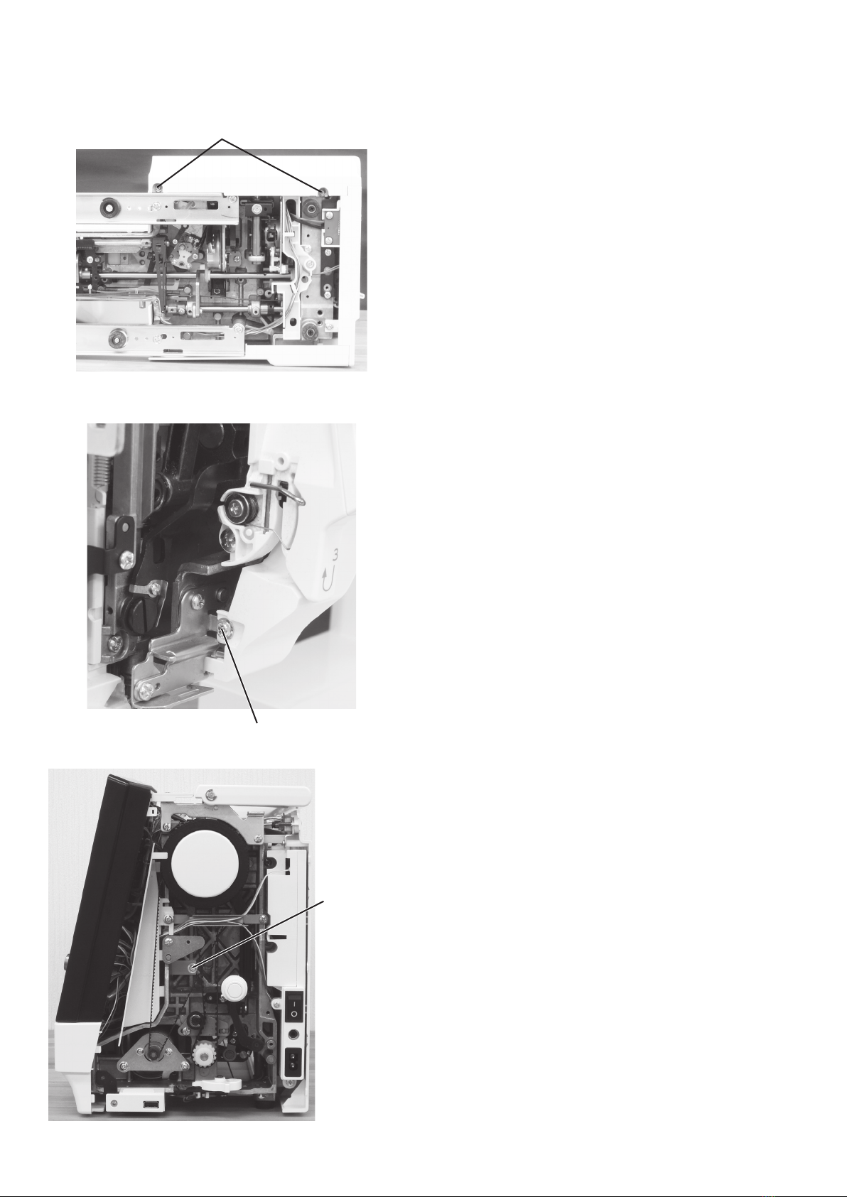
Horizon Fitness Memory Craft 9480 QC PROFESSIONAL Troubleshooting guide

SERVICE MANUAL
&
PARTS LIST
MODEL: HORIZON Memory Craft 9480
QC PROFESSIONAL
Second Edition: 08 August 2023

First Edition: 24 July 2023
Modied info.
Modied: 08 August 2023
P10 and 11: “Before replacing the printed circuit board A, copy the data in the board to a USB ash drive.
* Check the clear set mode (refer to page 45).” added.
P11: Replacing Electronic Components “Printed circuit board A” added.
Printed circuit board A connection: P10 →P11
P11 to 44 →P12 to 45
P45: deleted.


INDEX
Changing External Parts
Face cover .................................................................................................................................................................. 1
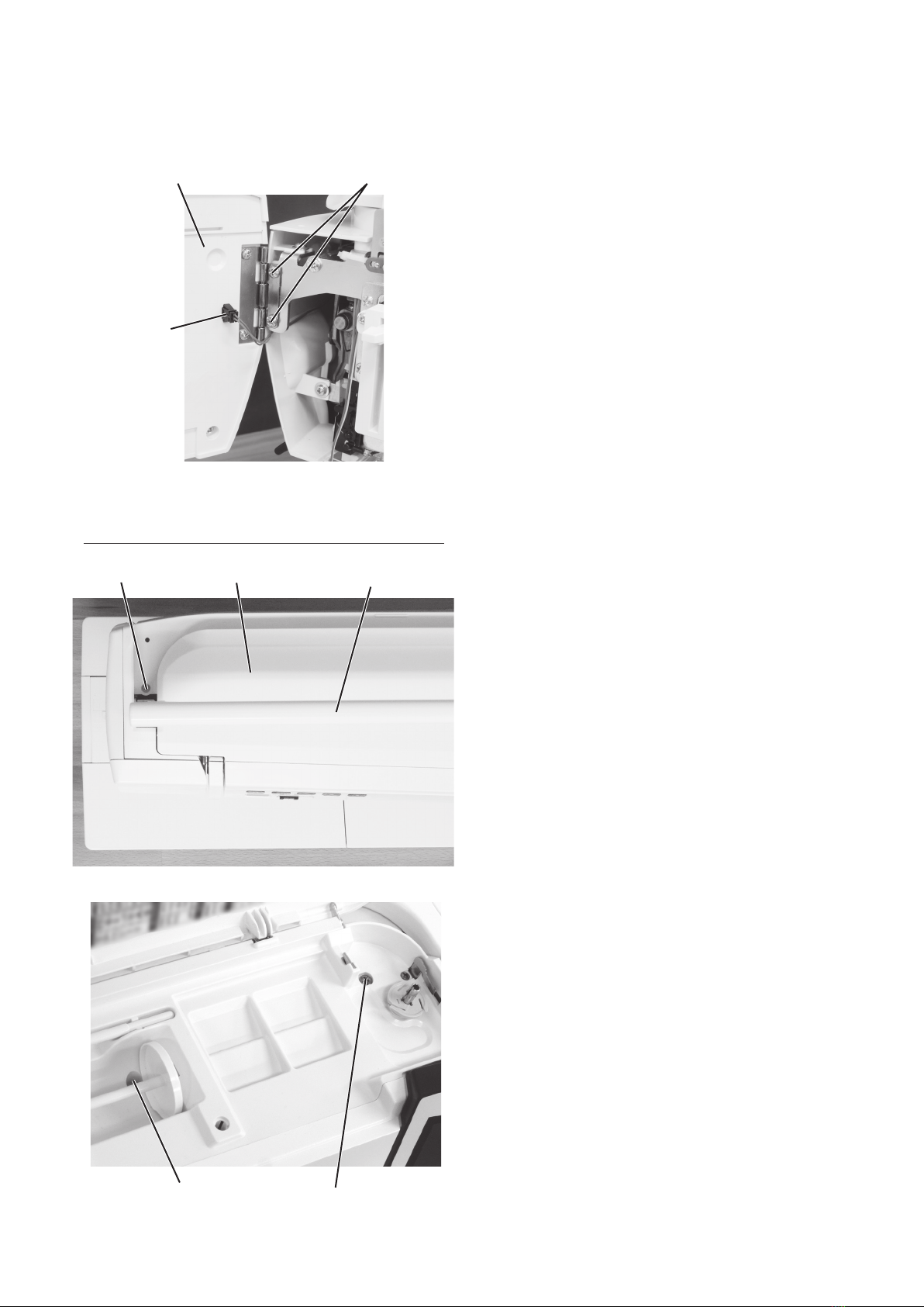
Top cover .................................................................................................................................................................... 1
Belt cover.................................................................................................................................................................... 2
Base plate................................................................................................................................................................... 3
Base cover.................................................................................................................................................................. 3
Bed cover ................................................................................................................................................................... 3
Free arm cover ........................................................................................................................................................... 4
Front cover ................................................................................................................................................................. 6
Rear cover .................................................................................................................................................................. 8
Replacing Electronic Components
Printed circuit board A case ...................................................................................................................................... 10
Printed circuit board A................................................................................................................................................11
Printed circuit board A connection .............................................................................................................................11
Printed circuit board F .............................................................................................................................................. 12
Switching power supply ............................................................................................................................................ 13
DC motor .................................................................................................................................................................. 14
Thread tension.......................................................................................................................................................... 15
Mechanical Adjustment
Feed dog height........................................................................................................................................................ 16
Needle drop position................................................................................................................................................. 17
Clearance between needle and tip of the rotary hook (method 1) ........................................................................... 18
Clearance between needle and tip of the rotary hook (method 2) ........................................................................... 19
Hook timing............................................................................................................................................................... 20
Needle bar height ..................................................................................................................................................... 21
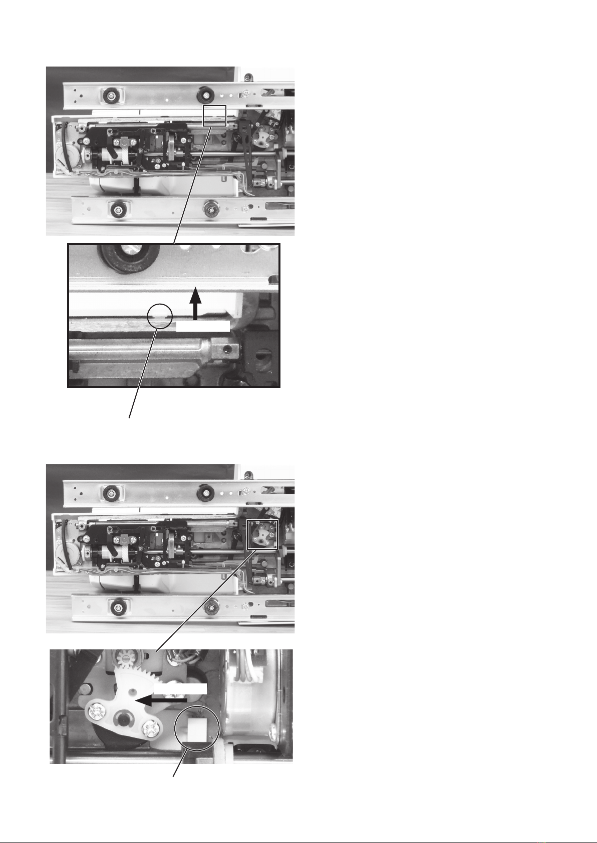
Backlash between hook drive gear and lower shaft gear ......................................................................................... 22
Upper shaft shield plate position .............................................................................................................................. 23
Upper thread tension ................................................................................................................................................ 24
Tension release mechanism ..................................................................................................................................... 25
Needle threader hook position ................................................................................................................................. 26
Needle threader release amount for the wire of the hook holder ............................................................................. 27
Thread drawing lever ................................................................................................................................................ 28
Upper feed dog (1) ................................................................................................................................................... 29
Upper feed dog (2) ................................................................................................................................................... 30
Upper feed dog (3) ................................................................................................................................................... 31
Buttonhole lever position .......................................................................................................................................... 32
Thread cutter ............................................................................................................................................................ 33
Presser bar lifter position .......................................................................................................................................... 34
Presser foot lifter stopper position (1)....................................................................................................................... 35
Presser foot lifter stopper position (2)....................................................................................................................... 36
Automatic presser foot lifter initializing position ........................................................................................................ 37
Preseer foot height on needle plate.......................................................................................................................... 38
Stretch stitch feed balance ....................................................................................................................................... 39
Needle plate switch .................................................................................................................................................. 40
Knee lifter ................................................................................................................................................................. 41
Embroidery foot height ............................................................................................................................................. 42
Brightness adjustment ....................................................................................................................................... 43
Touch panel key position adjustment ............................................................................................................ 44
Clear set mode ..................................................................................................................................................... 45
PARTS LIST .................................................................................................................................................. 46 to 75

1
Changing External Parts
Face cover
To remove:
1. Open the face cover.
Disconnect the connector from the face cover.
Remove the setscrews A (2 pcs.).
Remove the face cover.
To attach:
2. Follow the above procedure in reverse.
Setscrew A
Face cover
Top cover
To remove:
1. Raise the carrying handle.
Remove the setscrew B.
Lower the carrying handle.
Setscrew B Top cover
2. Open the top cover.
Remove the setscrew C and setscrew D.
3. Raise the carrying handle and remove the top cover.
To attach:
4. Follow the above procedure in reverse.
Carrying handle
Setscrew C Setscrew D
Connector

2
Changing external parts
Belt cover
To remove:
1. Raise the carrying handle.
2. Loosen the setscrew A.
Cap and setscrew C
Cap and setscrew C
3. Loosen the setscrew B.
Belt cover
Belt cover
Setscrew A
4. Remove the caps (2 pcs.) and the setscrews C
(2 pcs.).
5. Remove the belt cover.
To attach:
6. Follow the above procedure in reverse.
Setscrew B
Carrying handle

3
Changing external parts
Base plate
To remove:
1. Remove the setscrews A (2 pcs.) and setscrews B
(2 pcs.).
2. Remove the base plate.
To attach:
3. Follow the above procedure in reverse.
Setscrew B
Setscrew A
Setscrew A
Setscrew B
Base plate
Base cover
To remove:
1. Remove the extension table.
Remove the setscrews C (6 pcs.).
2. Remove the base cover.
To attach:
3. Follow the above procedure in reverse.
Bed cover
To remove:
1. Remove the extension table.
Remove the setscrews D (2 pcs.).
2. Remove the bed cover.
To attach:
3. Follow the above procedure in reverse.
Setscrew C
Setscrew C
Extension table
Setscrew C
Setscrew C
Base cover
Setscrew D
Setscrew D Bed cover

4
Free arm cover
To remove:
1. Remove the base plate and base cover (refer to
page 3).
Push down the needle plate release lever to remove
the needle plate.
Changing external parts
2. Remove the pin with the screwdriver.
Remove the bed cover (refer to page 3).
3. Loosen the setscrew.
Pin Bed cover
Needle plate
Free arm cover
Needle plate release lever
Setscrew

5
4. Unhook the hook A (front side of the free arm) and
move the free arm cover to the direction C.
Unhook the hook B (inside of the base plate) and
move the free arm cover to the direction D.
5. Slide the free arm cover to the left to remove the free
arm cover.
To attach:
6. Follow the above procedure in reverse.
Hook B
Hook A
Direction C
Direction D

6
Changing external parts
Setscrew A Front cover
To remove:
1. Remove the top cover, belt cover, base plate, base
cover and free arm cover (refer to pages 1 to 5).
2. Loosen the setscrews A (2 pcs.).
3. Loosen the setscrew B.
4. Loosen the setscrew C.
Setscrew B
(View from the bottom)
Setscrew C

7
5. Loosen the setscrew D.
6. Remove the setscrew E
Hook
7. Unlock the hooks from the front cover.
Remove the connectors from the circuit board A
(refer to page 11).
Remove the front cover.
To attach:
8. Follow the above procedure in reverse.
Refer to page 11 for how to connect/disconnect the
connectors to the printed circuit board A.
Setscrew E
Setscrew D
(View from the top)

8
Changing external parts
Setscrew B
Setscrew A
Connector
Face cover Rear cover
To remove:
1. Remove the top cover, base plate, base cover, bed
cover and free arm cover (refer to pages 1, 3 to 5).
2. Open the face cover.
3. Loosen the setscrew A.
4. Raise the carrying handle.
Carrying handle
5. Loosen the setscrew B.
Close the face cover.

9
Setscrew C
Setscrew D
Connector E
Connector G
Connector F
Cord binder
Hook
6. Remove the setscrews C (2 pcs.) and setscrews D
(2 pcs.).
7. Unlock the rear cover hooks from the front cover.
8. Disconnect the connector E, connector F and
connector G from the sockets.
Cut and remove the cord binder as necessary.
Remove the rear cover.
To attach:
9. Follow the above procedure in reverse.

10
Replacing Electronic Components
Printed circuit board A case
NOTE:
Do not disconnect the connectors by pulling on cord.
To disconnect the connectors, grasp the connector, not
the cord.
To remove:
1. Remove the front cover (refer to pages 6 and 7).
2. Grasp the connector directly with your ngers and
pull.
Do not pull the lead wire, as this may damage the
contact sleeve inside the connector.
Remove the setscrews (3 pcs.) and printed circuit
board A case.
To attach:
3. Follow the above procedure in reverse.
Be sure that the connector post on the printed circuit
board to which it is connected.
Position the connector correctly, then push it straight
down until it locks in place.
Setscrew
Setscrew
Before replacing the printed circuit board A, copy the data in the board to a USB ash drive.
* Check the clear set mode (refer to page 45).

11
Printed circuit board A connection
(1) (2) (3) (4) (5)
(6)
(7)
(8)
(9)
(10)
(11)
(12)
(13)
(14)
(15)
(16)
(22)
(23)
(24)
(25)
(26)
(27)
(28)
(29)
(21) (20) (19) (18)(17)
Bobbin winder switch
LCD (Flexible)
Touch panel (Flexible)
Printed circuit board L1 (black)
Printed circuit board L2 (white)
Printed circuit board L3 (red)
Slide volume
Printed circuit board F
Presser foot lifter switch
ErP switch (Auto-off timer switch)
BH sensor
Upper thread sensor
Knee lifter sensor
Power switch
Rotary encoder
Stitch regulator
Thread cutter motor
Remaining bobbin thread detecting sensor
Feed motor
Remaining bobbin thread detecting motor
Needle plate sensor
Drop feed detecting sensor (brown)
DC motor
Presser foot lifter motor
Thread tension motor
Zigzag motor
USB
Foot control & Thread cutter switch jack
Phase sensor
(1)
(2)
(3)
(4)
(5)
(6)
(7)
(8)
(9)
(10)
(11)
(12)
(13)
(14)
(15)
(16)
(17)
(18)
(19)
(20)
(21)
(22)
(23)
(24)
(25)
(26)
(27)
(28)
(29)
Printed circuit board A
NOTE:
Do not disconnect the connectors by pulling on cord.
To disconnect the connectors, grasp the connector, not
the cord.
To remove:
1. Remove the front cover (refer to pages 6 and 7).
2. Remove the setscrews (4 pcs.) and disconnect all the
connectors from the printed circuit board A.
Remove the printed circuit board A.
To attach:
3. Follow the above procedure in reverse.
Be sure that the connector post on the printed circuit
board to which it is connected.
Position the connector correctly, then push it straight
down until it locks in place.
Setscrew
Setscrew
Replacing Electronic Components
Before replacing the printed circuit board A, copy the data in the board to a USB ash drive.
* Check the clear set mode (refer to page 45).

12
Printed circuit board F
To remove:
1. Remove the front cover (refer to pages 6 and 7).
2. Disconnect the connectors from the printed circuit
board A (refer to page 11).
3. Remove the setscrew (6 pcs.).
4. Remove the printed circuit board F and remove the
speed control slider guide.
To attach:
5. Follow the above procedure in reverse.
Replacing Electronic Components
Setscrew
Setscrew
Printed circuit board F
Setscrew
Speed control slider guide

13
Switching power supply
To remove:
1. Remove the top cover, belt cover and front cover
(refer to pages 1, 2, 6 and 7).
2. Loosen the setscrew A and remove the cord guide
plate.
Replacing Electronic Components
Switching power supply
Setscrew A Setscrew B
Setscrew B
Power
supply
connector
Cord guide plate
Power supply connector
3. Disconnect the power supply connector from the
switching power supply unit.
4. Remove the setscrews B (3 pcs.) and the switching
power supply.
To attach:
5. Follow the above procedure in reverse.
Switching
power supply

14
300 gf pressure
7 to 9 mm
Setscrew
Setscrew
DC motor
To remove:
1. Remove the top cover, belt cover and front cover
(refer to pages 1, 2, 6 and 7).
2. Remove the setscrews (2 pcs.) and the motor belt.
Remove the DC motor.
Replacing Electronic Components
To attach:
3. Attach the DC motor.
Tighten the setscrews (2 pcs.) temporarily.
4. Adjust the motor belt deection to about 7 to 9 mm by
pressing the middle of the motor belt with your nger
with approximately 300 grams-force of pressure.
5. Tighten the setscrews (2 pcs.) securely.
6. Attach the front cover, belt cover and top cover.
Motor belt
DC motor
DC motor

15
Replacing Electronic Components
Setscrew A Thread tension unit
To remove:
1. Remove the top cover, belt cover and the front cover
(refer to pages 1, 2, 6 and 7).
2. Remove the setscrews A and B.
3. Cut the cord binder. Be careful not to cut the cords.
Remove the setscrew C and cords from the nylon
clip.
Remove the nylon clip.
Remove the thread tension unit.
Setscrew B Thread tension unit
Cord binder
Setscrew C
Nylon clip
To attach:
4. Follow the above procedure in reverse.
5. Check the upper thread tension (refer to page 24).
(View from the top)

16
Mechanical Adjustment
Nut
Setscrew A Adjusting screw
Presser foot
(zigzag foot A)
0.90 to 1.00 mm
Surface of
needle plate
Feed dog
Hexagonal socket screw
Setscrew B
Threaded hole
Feed dog height
When the foot presser foot pressure value is at “6” and the presser foot is lowered, the highest position of
the feed dog should be 0.90 to 1.00 mm from the surface of the needle plate.
Adjusting screw
Threaded hole
Setscrew A
Setscrew B
Adjustment 1:
1. Attach the zigzag foot A.
Remove the base cover and bed cover (refer to
page 3).
2. Turn the power switch ON.
Adjust the stitch length to the maximum (5.0).
3. Press the presser foot lifter button to lower the
presser foot.
4. Turn the handwheel toward you to raise the feed dog
to its highest position.
5. Loosen the setscrew A.
6. Loosen the nut with a socket wrench.
Turn the adjusting screw and adjust the feed dog
height to 0.90 to 1.00 mm.
7. Tighten the nut and setscrew A.
8. Turn the handwheel and check that the feed dog
teeth are in parallel with the surface of the needle
plate. If not, follow the adjustment procedure below.
Adjustment 2:
If the feed dog is not parallel to the surface of the needle
plate at its highest position, make the adjustment as
follows:
* For this adjustment, a hexagonal socket screw 4x6,
part No. 000111108 is required.
1. Insert a hexagonal socket screw, part no. 000111108
into the threaded hole until it stops.(use an Allen
wrench of 2 mm width across ats).
2. Turn the setscrew B (left hand screw) clockwise to
loosen it.
3. Turn the hexagonal socket screw I until the feed dog
is parallel with the surface of the needle plate.
4. Tighten the setscrew B by turning it counterclockwise.
5. Remove the hexagonal socket screw.
6. Attach the bed cover and base cover.
Table of contents
Other Horizon Fitness Sewing Machine manuals