Copyright © All Rights Reserved to Horizon Educational Group
www.horizoncurriculum.com
TEACHER GUIDE
UNIT 3
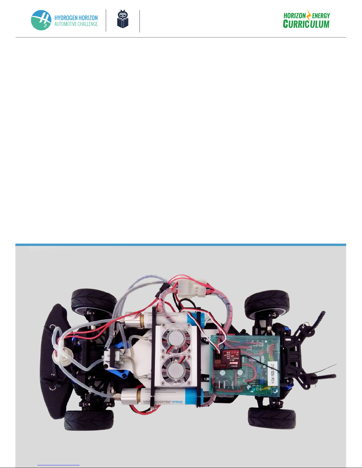
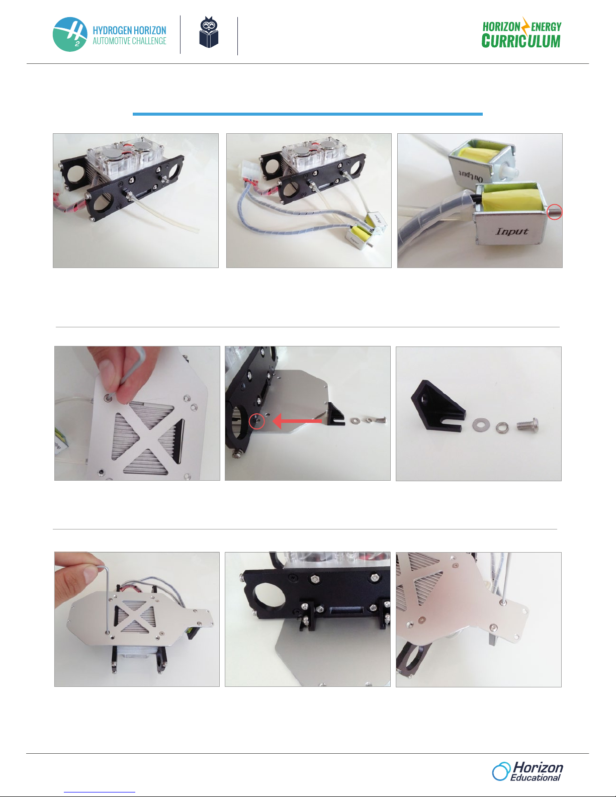
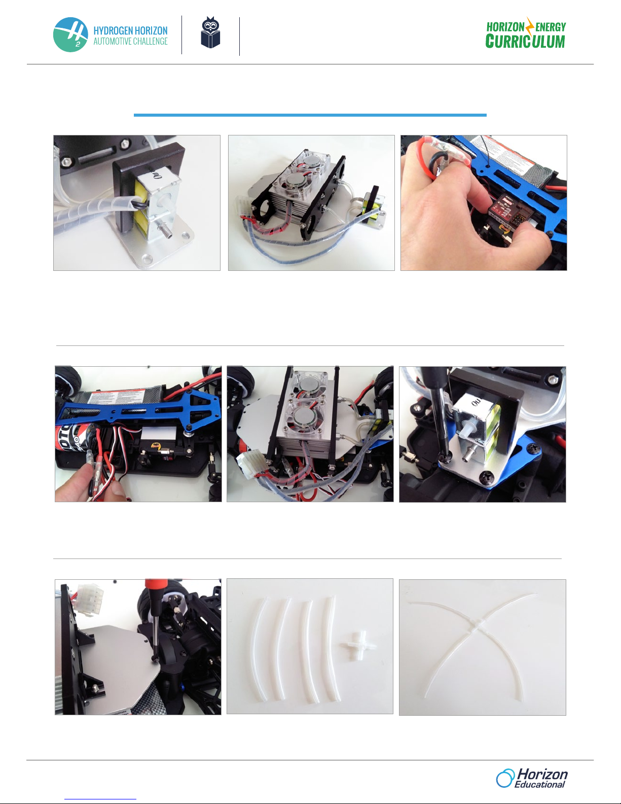
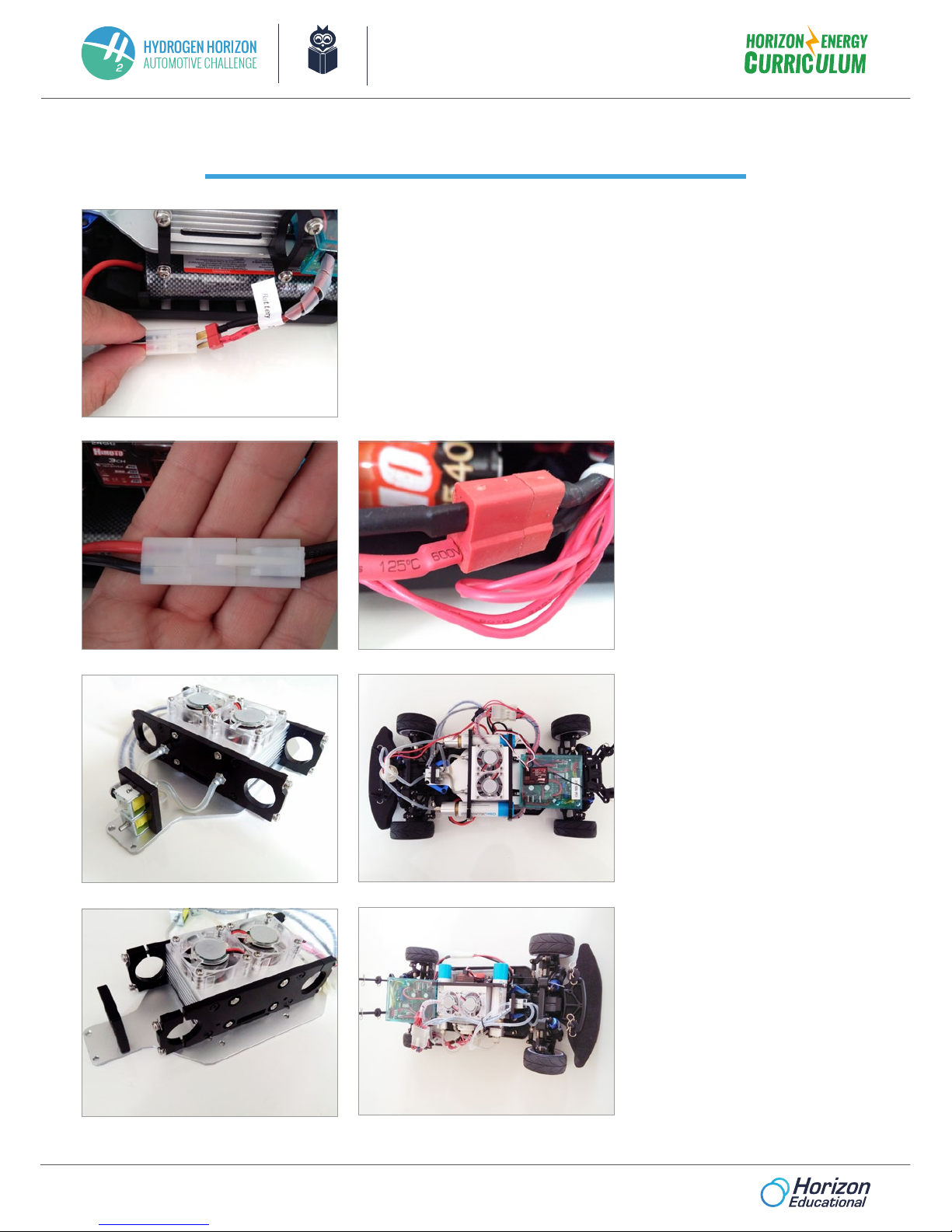
Assembly Manual: H-Cell 2.0 and Himoto
Equipped with a high performance running battery and motor, the RC car models
are capable of speeds of over 50km/h. Operating RC models in improper areas
may result in accidents causing injury or property damage. Follow the instructions
outlined below to fully enjoy operating your RC car.
1. Operate RC models in appropriate areas only.
a. Never run RC models on the road.
b. Never run RC models in a crowded area or near small children.
c. Do not run RC models in a narrow space or indoors.
2. Never touch any rotating parts such as wheels, shafts or gears, as your ngers,
hair, clothes etc. may get caught, leading to serious injury.
3. When not in use, always disconnect and remove both the battery and the
hydrogen canister.
4. Do not dissasemble the battery, fuel cell, or Hydrostik cartridges, nor cut the
cables.
5. Make sure you recharge the battery and fuel cell correctly, please follow the
instructions.
6. After use, the battery retains heat. Please wait until it cools down before
recharging. Please dispose of the battery responsibly. Never put a battery
into re.
7. Immediately stop running the RC model if it gets wet, as it may short circuit.
8. Do not tamper, disassemble or puncture the Hydrostik cartridges.
9. Keep assembled RC model and/or Hydrostik cartridges away from re, open
ame, or heat source.
SAFETY INFORMATION
Please read before proceeding to assembly