4
EN
Charging Warnings
Battery Charging
First Flight Preparation
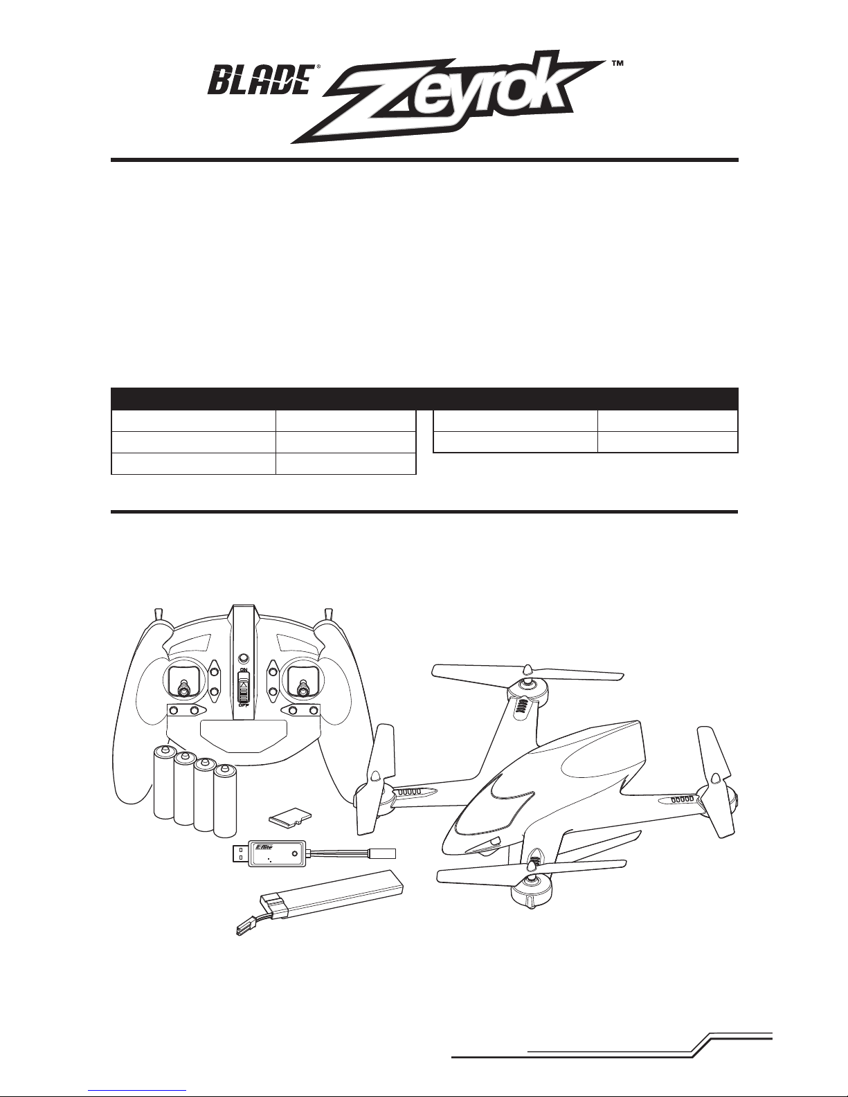
• Remove and inspect contents
• Begin charging the flight battery
• Program your computer transmitter (BNF only)
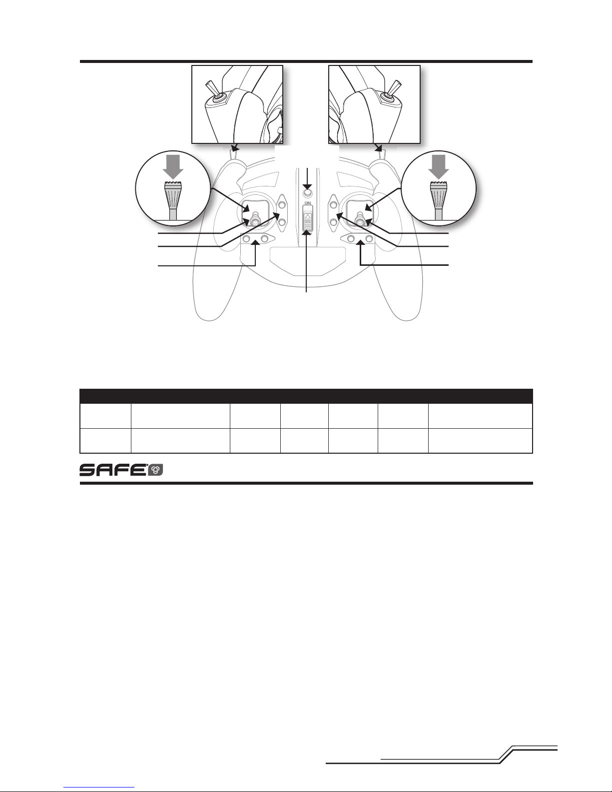
• Familiarize yourself with the controls
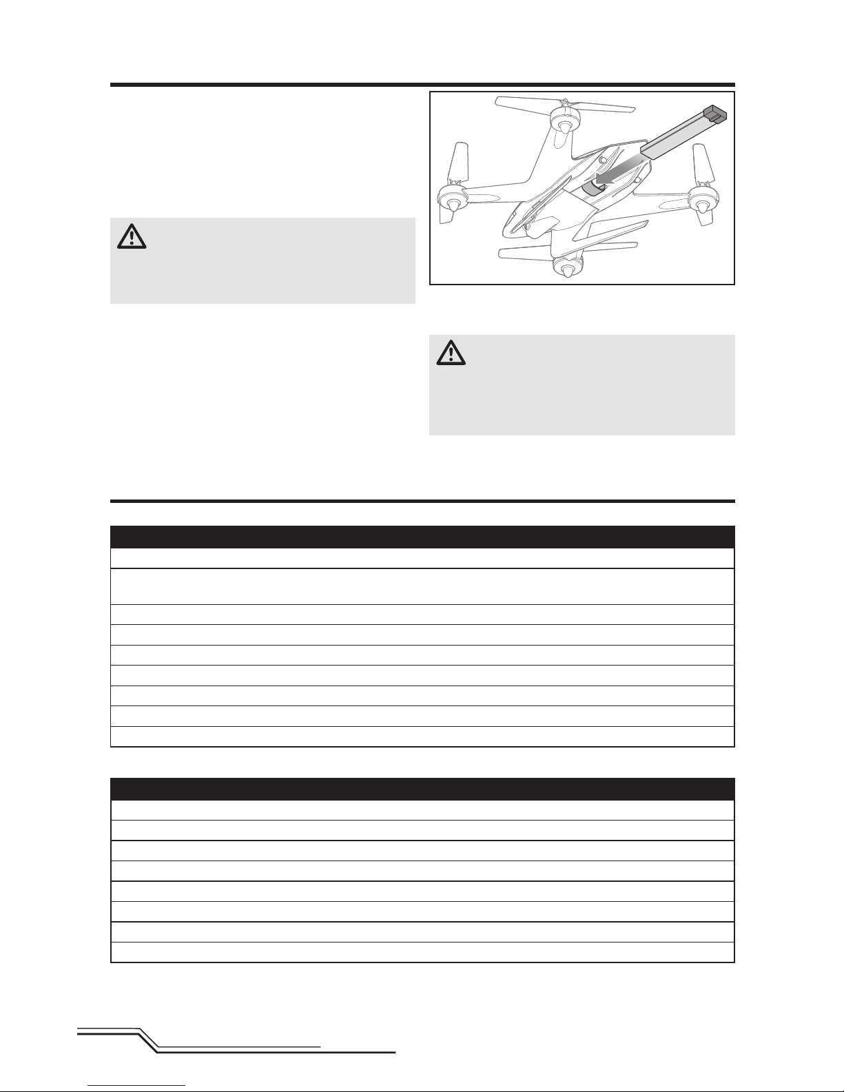
• Install the flight battery in the quadcopter
(once it has been fully charged)
• Bind your transmitter
• Find a suitable area for flying
Flying Checklist
❏Always turn the transmitter on first
❏Plug the flight battery into the lead from the 3-in-1 ESC
❏Allow the receiver and ESC to initialize and arm
❏Fly the model
❏Land the model
❏Unplug the flight battery from the 3-in-1 ESC
❏Always turn the transmitter off last
CAUTION: All instructions and warnings must
be followed exactly. Mishandling of Li-Po batter-
ies can result in a fire, personal injury and/or property
damage.
• NEVER LEAVE CHARGING BATTERIES UNATTENDED.
• NEVER CHARGE BATTERIES OVERNIGHT.
• By handling, charging or using the included Li-Po battery,
you assume all risks associated with lithium batteries.
• If at any time the battery begins to balloon or swell,
discontinue use immediately. If charging or discharging,
discontinue and disconnect. Continuing to use, charge
or discharge a battery that is ballooning or swelling can
result in fire.
• Always store the battery at room temperature in a dry
area for best results.
• Always transport or temporarily store the battery in a
temperature range of 40–120º F (5–49° C).
• Do not store battery or model in a car or direct sunlight.
If stored in a hot car, the battery can be damaged or
even catch fire.
• Always charge batteries away from flammable materials.
• Always inspect the battery before charging.
• Always disconnect the battery after charging, and
let the charger cool between charges.
• Always constantly monitor the temperature of the
battery pack while charging.
• ONLY USE A CHARGER SPECIFICALLY DESIGNED TO
CHARGE LI-PO BATTERIES. Failure to charge the battery
with a compatible charger may cause a fire resulting in
personal injury and/or property damage.
• Never discharge Li-Po cells to below 3V under load.
• Never cover warning labels with hook and loop strips.
• Never charge batteries outside recommended levels.
• Never charge damaged batteries.
• Never attempt to dismantle or alter the charger.
• Never allow minors to charge battery packs.
• Never charge batteries in extremely hot or cold places
(recommended between 40–120° F or
(5–49° C) or place in direct sunlight.
NOTICE: Charge only batteries that are cool to the touch
and are not damaged. Look at the battery to make
sure it is not damaged e.g., swollen, bent, broken or
punctured.
1. Insert the charger into a USB port.
2. Connect the battery to the charger lead, noting the
correct polarity.
3. Always disconnect the flight battery from the charger
immediately upon completion of charging.
CAUTION: Only use chargers specifically designed
to charge the included Li-Po battery. Failure to do so
could result in fire, causing injury or property damage.
CAUTION: Never exceed the recommended
charge rate.
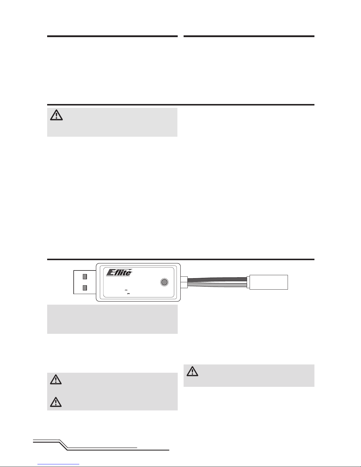
LED Indications
When you make the connection successfully, the LED on
the charger turns solid red, indicating charging has begun.
Charging a fully discharged (not over-discharged) 750mAh
battery takes approximately 60 minutes. The light goes off
when the charge is complete.
CHARGING (Solid Red)
MAX CHARGE (OFF)
CAUTION: Once charging is complete, immedi-
ately remove the battery. Never leave a battery
connected to the charger.
USB Li-Po
Charger
EFLC1014
SOLID RED LED
–Charging
DC Input:5.0V 750mA
DC Output:4.2V 700mA
LED OFF
–Charge
Complete


 user manual")


