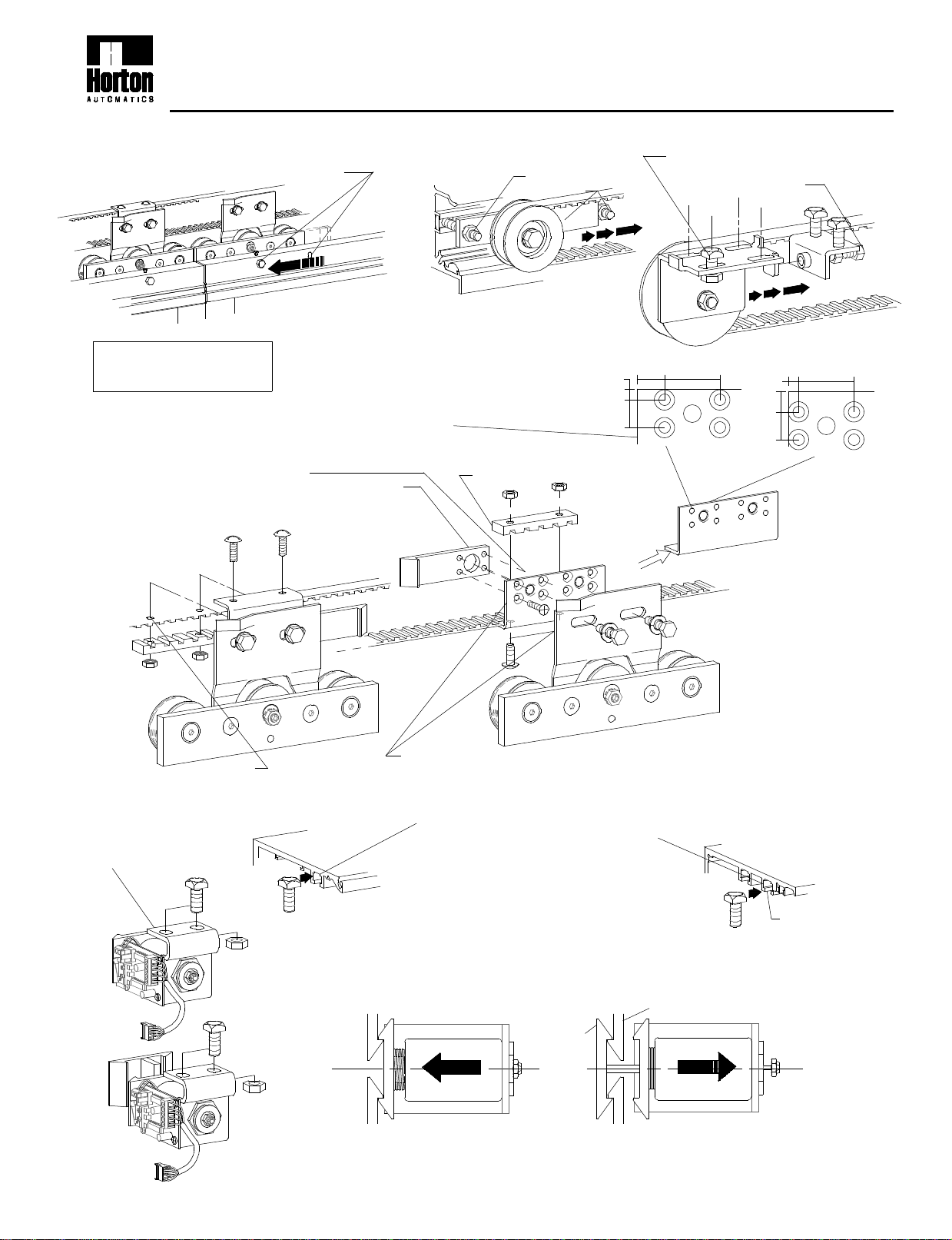
manuals.online logo
Brands
  1. Home
  2. •
  3. Brands
  4. •
  5. Horton
  6. •
  7. Industrial Equipment
  8. •
  9. Horton S200 User manual

Horton S200 User manual

Door panels and
header not shown
for clarity
Re-position the close monitor switch. Re-tighten the belt.
Slide 2 square head bolts into the "T"
slot in the top of the header.
Place the bolts in the center of the header.
Access is gained through relief holes
cut in the "T" slot.
(additional relief holes may be cut if required)
•Place the Autolock at the centerline of the header and mount
with 5/16" nuts and washers (do not tighten).
•Place the door in the fully closed position - the lock should
contact the keepers with out binding.Tighten the 5/16"(2003) or 3/8"(2001) nuts.
Install the brackets to the wheel
carriages as shown
7th Step
Fail secure
top view locked
SOLENOIDSOLENOID
5th Step
Fail
safe
2003
Fail
secure
2003
See page 4 for
Autolock setup
9th Step
Re-connect the belt through
the existing holes.
6th Step
2003 lock is shown
2001 lock is similar
8th Step
2003
Keepers
top view locked
SOLENOID
Fail safe
Lock hooks
L
C
2.205d
2001
First slot
Autolock Installation for 2001 & 2003 Bipart units
BELT DRIVE SUPPLEMENTAL INSTRUCTIONS
2nd Step
Loosen the belt.
Remove the belt connections
3rd Step
NOTE: If necessary the existing bracket
may be drilled and countersunk for #10
screws as shown.
CAUTION:
Disconnect power before
starting this procedure.
•Remove the old belt brackets
•Install the keepers on the new belt brackets
with countersunk holes using 4 #10 FHMS
4th Step
If the wheel carriages are located at the 9 1/2" position
they must be moved to the 4 7/16" position
1st Step
1-800-531-3111
1/2"
13/64" 1"
1/2"
2003 2001
3/16" 1"
3/8"
1/2"
2001
Loosen bolts (on the pully bracket)
and remove belt tension by backing
off the idler pully lock.
Loosen bolts and
slide idler
2003
S200
10/99
"SX" PANEL
"O" PANEL
See page 4 for
Autolock setup
•Install a new continuous belt
•Make splice connection at the drive assembly
•Tension the new belt
"O" PANEL
4th Step
2.206d
Mount the autolock and relocate the
closed monitor switch
(see steps 7,8 & 9 page 1)
"SX" PANEL
5th Step
Put the door at full open and mark this position.
The belt idler will have to be moved beyond this point.
Autolock Installation for 2001 & 2003 O-SX units
BELT DRIVE SUPPLEMENTAL INSTRUCTIONS
"SX" PANEL
Move the idler to the end of the header.
(allow space for tightening)
2nd Step
1-800-531-3111
1st Step
•Dismount the wheel carriages and move the
drive assembly to the back and the idler to the
front.
•Mount the keeper to the drive assembly.
(see steps 3 thru 6 page 1)
3rd Step
CAUTION:
Disconnect power before
starting this procedure.
S200.1
10/99
MOTOR
Mount the autolock and relocate the
closed monitor switch
(see steps 7,8 & 9 page 1)
"SX" PANEL
6th Step
•Install a new continuous belt
•Make splice connection at the drive assembly
NOTE:Connect to lower belt
•Tension the new belt
5th Step
"SX" PANEL
POWER
SUPPLY
See page 4 for
autolock setup
"O" PANEL
CONTROL
2.207d
MOTOR
•Move the power supply, control and motor
to the right end of the header as shown.
NOTE: Motor and gear drive should be
against the end cap for proper position.
4th Step
"O" PANEL
Disconnect and remove the belt.
A new belt will be installed later
BELT DRIVE SUPPLEMENTAL INSTRUCTIONS
Autolock Installation for 2001 & SX-O units
•Dismount the wheel carriages and move the
drive assembly to the back and the idler to the
front.
•Mount the keeper to the drive assembly.
(see steps 3 thru 6 page 1 )
NOTE:
Leave idler at the far end of
the header - run the belt full
length.
2nd Step
1-800-531-3111
"SX" PANEL
1st Step
•Dismount the power supply and re-position
left of the control.
NOTE:
Incoming 120VAC may need additional length added.
5 conductor lace may need additional length.
POWER
SUPPLY
CONTROL
3rd Step
CAUTION:
Disconnect power before
starting this procedure.
"O" PANEL
CONTROL POWER
SUPPLY
10/99
S200.2
Lock
monitor SW
Fail safe
Press SET and RESET simultaneously, release
RESET, wait 5 seconds,then release SET - version
number will displayed.
During initialization the control clears all ports and
the solenoid becomes inactive.
NOTE: See H202 Rev. 9/99 for further information and trouble shooting Autolocks.
AUTOLOCK SET UP AND INITIALIZATION
O
LOCK
LOCK
MON
Y
+100
LOCK
LOCK
MON
LOCK
LOCK
MON
eO
R
Y
O
+100
Y
If the yellow LED is off...
FAIL SECURE
s
SOLENOID
l
Rn
If there is no response it
knows there is no lock.
The control sends a pulse
to retract the solenoid... If the control gets a
response back, it
knows there is a fail
secure lock.
The C2150 looks to see if there is a contact at the
lock port CN4 and if the yellow lock monitor LED
is off.
R
+100
LOCK
MON
LOCK
Y
O
LOCK
LOCK
MON
LOCK
LOCK
MON
ln
Y
as
If the yellow LED is on...
SOLENOID
O
+100
R
O
Y
FAIL SAFE
The control sends a pulse
to retract solenoid...
If there is no response it
knows there is no lock.
The C2150 looks to see if there is a contact at the
lock port CN4 and if the yellow lock monitor LED
is on.
If the control gets a
response back, it
knows there is a
fail safe lock.
2.208d
Autolock Setup & Initilization for 2001 & 2003 units
BELT DRIVE SUPPLEMENTAL INSTRUCTIONS
Set jumpers as shown
for fail secure or fail safe
Fail secure
(Orange)
LOCK
UP DOWN SET
CN5
CN4
D1
RESET
1
1-800-531-3111
CODE
DISPLAY
FAIL SECURE
Remains lockedat power failure
TS 2
TS 1
Lock
monitor SW 5
1
Unlocks at power failure
FAIL SAFE
(Yellow)
TS 2
LOCK
MON
TS 1
Connect to CN 4
S200.3
10/99

Popular Industrial Equipment manuals by other brands

ABB SCK operating instructions

ABB

ABB SCK operating instructions

Tronair JP30 Operation & service manual

Tronair

Tronair JP30 Operation & service manual

ITW Gema EASY 1-L Operating instructions and spare parts list

ITW Gema

ITW Gema EASY 1-L Operating instructions and spare parts list

SENSY 5950 Series installation manual

SENSY

SENSY 5950 Series installation manual

Emerson Fisher DFA instruction manual

Emerson

Emerson Fisher DFA instruction manual

Sapcon VITAL-T instruction manual

Sapcon

Sapcon VITAL-T instruction manual

Eaton Cooper Power VFI SF6 Installation, operation and maintenance instructions

Eaton

Eaton Cooper Power VFI SF6 Installation, operation and maintenance instructions

ABB HT585050 Operation manual

ABB

ABB HT585050 Operation manual

ProMinent CHLORINSITU V operating instructions

ProMinent

ProMinent CHLORINSITU V operating instructions

ABB HT609075 Operation manual

ABB

ABB HT609075 Operation manual

SICK InspectorP62 Series operating instructions

SICK

SICK InspectorP62 Series operating instructions

Carlisle Ransburg RP-404 Service manual

Carlisle

Carlisle Ransburg RP-404 Service manual

Trane LonWorks TR200 instruction manual

Trane

Trane LonWorks TR200 instruction manual

ABB HT563146 Operation manual

ABB

ABB HT563146 Operation manual

Fike SRX Installation and maintenance instructions

Fike

Fike SRX Installation and maintenance instructions

JST MKS-L instruction manual

JST

JST MKS-L instruction manual

REMS Unimat 75 instruction manual

REMS

REMS Unimat 75 instruction manual

Keith CleenSweep Manual owner's manual

Keith

Keith CleenSweep Manual owner's manual

manuals.online logo
manuals.online logoBrands
  • About & Mission
  • Contact us
  • Privacy Policy
  • Terms and Conditions

Copyright 2025 Manuals.Online. All Rights Reserved.