Hosa Technology CBT-375 User guide

Hosa CBT-375 Cable Tester
Applications Guide
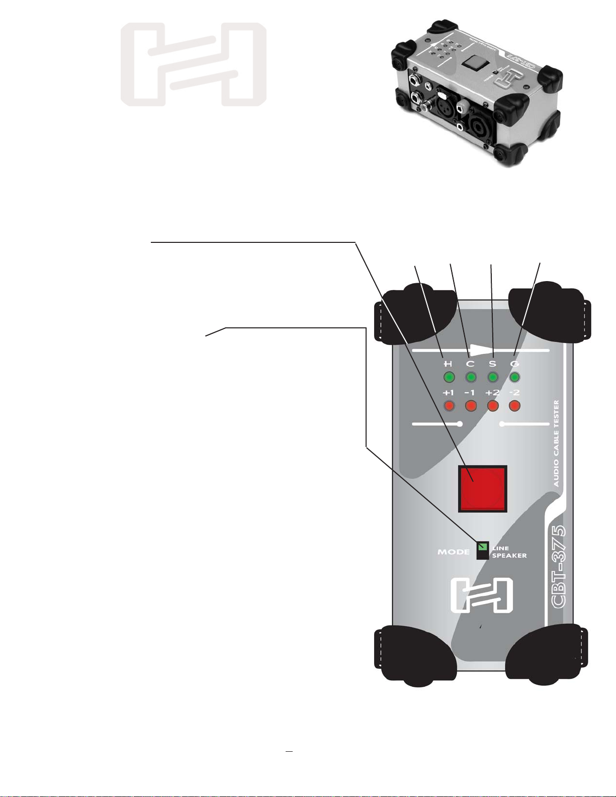
OVERVIEW: To test a cable, plug one end of the cable
into the right side of the tester, and the other end of the
cable into the left side of the tester, and then push the
square red button
in the center of the top panel. Lights on the top panel
will blink in sequence as the tester does its work. When
it is finished testing the cable, various combinations of
green and red lights will be illuminated for several sec-
onds to indicate the way the cable is wired.
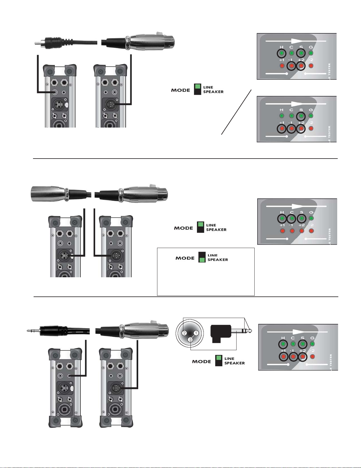
In general, when the MODE Switch is in the LINE posi-
tion, a green light indicates a proper “through connec-
tion”, no green light indicates “no connection”, and a red
light indicates a “bridged connection”. NOTE: A red light
does not necessarily indicate incorrect wiring. An XLR
to unbalanced 1/4” Phone cable, for example) requires
that the Cold and Shield be bridged at the XLR.
When the MODE Switch is in the SPEAKER position,
(for the testing of Speakon-to-Speakon, Speakon-to-
1/4”, Speakon-to-Banana, and 1/4” to Banana), green
lights indicate good through connections. Proper polari-
ty must be observed when testing banana-plug cables
to get a good test. (Make sure the “ground tab” of the
banana plug is in the lower position.) Improperly wired
banana cables (or banana cables plugged into the
tester upside-down) will light Red LEDs.
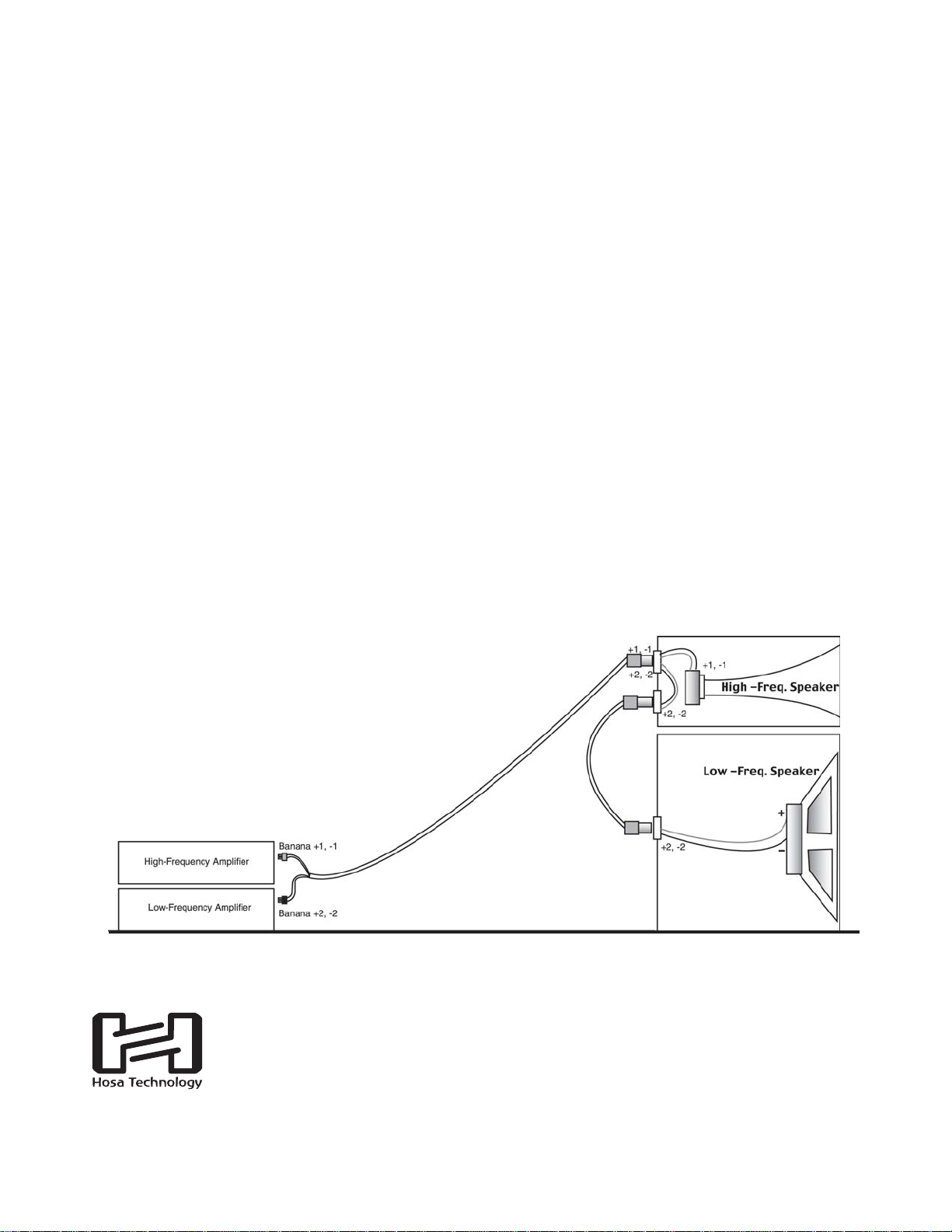
If you’re testing speaker cables that use Speakon
and/or dual banana connectors, and/or 1/4” phone,
make sure to first switch the MODE SWITCH
to “SPEAKER” before testing. Also, use the “SPEAK-
ER” MODE to check for chassis grounding* in an XLR
cable. Otherwise, leave the MODE switch in the “LINE”
position.
Hot Cold Shield
*The shell or “chassis” of an XLR connector is the part you hold when plugging it in. Some cable manufacturers connect Pin 1
(Shield) to the chassis. Most do not. (Hosa does not.) While neither way is right or wrong, it’s important to know if your cable has
chassis ground when you’re troubleshooting hums and buzzes in audio systems, since chassis ground can actually help propagate
noise due to ground “loops”. An illuminated red or green GLED indicates that one or both XLRs are grounded to chassis. THIS
TEST MUST BE RUN WITH THE MODE SWITCH IN THE “SPEAKER” POSITION, to activate the “G” LED lights.
Chassis
Ground *
NOTE: THIS UNIT INCLUDES A NEW 9-VOLT BATTERY. OPEN THE BATTERY
COMPARTMENT ON THE BOTTOM OF THE CASE, USING A SMALL PHILLIPS
SCREWDRIVER. UNWRAP THE BATTERY, CONNECT IT TO THE BATTERY
RECEPTACLE, AND REPLACE THE BATTERY & COMPARTMENT COVER. DIM
LEDs USUALLY INDICATE THAT IT’S TIME TO REPLACE THE BATTERY.
REMOVE THE BATTERY WHEN STORING UNIT FOR LONG PERIODS.

B
O
T
T
O
M
B
O
T
T
O
M
T
O
P
T
O
P
LEFT SIDE RIGHT SIDE
(BOTTOM)
1/4” TS
MONO
XLR MALE
SPEAKON
DUAL
BANANA
XLR FEMALE
(BOTTOM)
RCA (BOTTOM)
RCA
(BOTTOM)
1/4” TS
MONO
(TOP)
1/4” TRS
STEREO
(TOP)
3.5MM
STEREO
The diagram at the right shows the orientation
of the jack bays on the CBT-375. Notice that
the BOTTOM 1/4” Jacks are MONO TS
(tip/sleeve) jacks. The TOP 1/4” Jacks are
STEREO TRS (tip/ring/sleeve). Please notice also
that the XLR Female jack is on the LEFT SIDE,
and the XLR Male jack is on the RIGHT SIDE.
The LED lights on the top panel are referenced to
the jacks on the RIGHT SIDE of the tester (see dia-
gram above).This means that the “H C S and G”
LED green and red lights refer to “HOT, COLD,
SHIELD and GROUND” of the jack on the RIGHT
SIDE. (Or, when testing speaker cables that have
Speakon plugs, the LED lights refer to the “+1, -1,
+2, -2” contacts of the Speakon plug connected to
the RIGHT SIDE.) Why is this distinction important?
The reason is that many cable assemblies use
three-or-four-conductor plugs at one end (TRS 1/4”,
TRS 3.5mm, XLR or Speakon) and only two-con-
ductor plugs at the other end (TS 1/4”, RCA,
banana, etc.) It will be less confusing, therefore,
when connecting such cables, to always connect
the end of the cable with more than two contacts to
the jacks on the RIGHT-SIDE. The exception would
be a cable with a Male XLR plug, since the only
Female XLR jack on the CBT-375 is on the Left
Side. Diagrams that follow show which LEDs light-
up when the cable is wired correctly, for the various
cable configurations that the CBT-375 can test.
GOOD TEST
GOOD TEST
GOOD TEST
TS 1/4” (MONO or UNBALANCED)
TRS 1/4” (STEREO or BALANCED)
RCA
SIDE-PANEL JACK BAYS
top jacks
bottom jack bottom jack
Unlike the unbalanced 1/4” plugs, RCA’s are referenced to the
Hand S
SLEDs due to internal bussing requirements in the tester.

LEFT SIDE RIGHT SIDE
MONO 1/4” to RCA
GOOD TEST
top jack
WHY DOES THE RED SLIGHT UP?: Notice that for this test, we connect the unbalanced 1/4” plug to the TOP 1/4”
Jack. (This odd configuration is made necessary by the internal bussing of the CBT-375, which keeps the unbalanced
1/4” jack separate from the RCA, in order to facilitate a wider variety of tests.) In a “good test”, the green Hand S
LEDs will illuminate to indicate good through-connections. You may ignore the red S LED, which lights because we’ve
used the balanced jack for the unbalanced 1/4” plug in this test only. But if the red HLED illuminates, that would indi-
cate that cable repair is needed, due to a “bridged” (short) condition in the cable.
LEFT SIDE RIGHT SIDE
GOOD TEST for PIN 2 HOT
GOOD TEST for PIN 3 HOT
XLR (M) to TRS 1/4” (BALANCED)
TRS 1/4” (BALANCED) TO XLR (F)
Not all monufacturers of audio gear agree upon a standard for connecting 3-pin
XLR plugs to other kinds of plugs. Most manufacturers are specifying Pin 2 as the
“hot” pin and Pin 3 as the “cold” pin. The differences in good tests for Pin 2 Hot,
and Pin 3 Hot are shown at the right.
Exception: Use the top
1/4” Jack for this test.

GOOD TEST:
top jack
GOOD TEST for PIN 2 HOT
GOOD TEST for PIN 3 HOT
GOOD TEST for PIN 2 HOT
GOOD TEST for PIN 3 HOT
XLR (M) to TS 1/4” (UNBALANCED)
TS 1/4” (UNBALANCED) TO XLR (F)
XLR (M) to RCA (UNBALANCED)
In a properly wired unbalanced cable such as this one, Pin 1 and Pin 3 of the XLR (representing Shield and Cold,
respectively) are bridged. The red LEDs under “C” (Cold) and “S” (Shield) will illuminate to show this condition.
In a properly wired unbalanced cable such as this one, Pin 1 and Pin 3 of the XLR (representing Shield and Cold,
respectively) are bridged. The red LEDs under “C” (Cold) and “S” (Shield) will illuminate to show this condition.
In this tester, the RCA jacks are referenced to the H(Hot) and S(Shield) LEDs. In a properly wired, Pin 2 Hot unbal-
anced cable such as this one, Pin 1 and Pin 3 of the XLR (representing Shield and Cold, respectively) are bridged.
The red LED under “S” (Shield) illuminates to show this condition. Since the LEDs are referenced to the jacks on
the right, and since the RCA jack has only two contacts (Hot and Shield) the red C(Cold) LED does not illuminate.
top jack
Exception: Use the top
1/4” Jack for this test.
Exception: Use the top
1/4” Jack for this test.

GOOD TEST
GOOD TEST
GOOD TEST for PIN 2 HOT
GOOD TEST for PIN 3 HOT
RCA (UNBALANCED) to XLR (F)
XLR (M) to XLR (F)
XLR (F) to Stereo 3.5mm
For this cable, the LEDs (being referenced to the jacks on the right) are referenced to the XLR female
end. In a properly-wired Pin 2 Hot cable such as this, Pins 1 and 3 of the XLR (representing Shield and
Cold respectively) are bridged. The red LEDs under Cand S, will therefore illuminate. Only the H and S
green LEDs will light, showing good through connections to both contacts of the RCA.
This cable (Hosa’s model XVM-105) feeds a mono audio signal
equally to both Left and Right contacts in a personal portable device’s
stereo input. Pins 1 and 3 are bridged, and Hot and Cold of the
3.5mm plug are bridged to Pin 2.
To rule-out or confirm “chassis
ground” (headshells shorted to
shield), run test again in “Speaker”
Mode, which activates the GLEDs.

GOOD TEST,
4 Conductor Cable
GOOD TEST,
2 Conductor Cable
For Testing Speakon cables, be sure to first switch the MODE Switch
to the SPEAKER position.
LEFT SIDE RIGHT SIDE
3.5mm (STEREO)
3.5mm (STEREO) to 1/4” (STEREO)
Speakon™ to Speakon™
GOOD TEST
GOOD TEST
top jack
Speaker Cables

GOOD TEST:
GOOD TEST:
GOOD TEST:
GOOD TEST:
GOOD TEST:
Observe proper polarity when con-
necting Banana plugs. The Banana
plug should be oriented with the
“Ground Tab” in the lower position.
Otherwise your test will show two
Red LEDs!
Observe proper polarity when connecting Banana plugs. The Banana
plug should be oriented with the “Ground Tab” in the lower position.
Otherwise your test will show two Red LEDs!
Banana to Speakon™
1/4” to Speakon™
1/4” to Banana
bottom jack
bottom jack
ground tab For Speakon to one Banana, the test is
straightforward and yields results shown
above right.
For Speakon to TWO Bananas, test first
one banana as above, and then test again
using the second banana. Test results will
show which Banana is connected to Pins
+1, -1 or +2, -2 of the Speakon.
For Speakon to one 1/4” plug, the test is
straightforward and yields results shown
above right.
For Speakon to TWO 1/4”, test first one
1/4”, and then test again using the second
1/4”. Test results will show which 1/4” plug
is connected to Pins +1, -1 or +2, -2 of the
Speakon.
ground tab

NOTES:
Speakon™ is a trademark of Neutrik, and refers to their 4 and 8-pole connectors used on many brands of speak-
ers and audio amplifiers and the cables that connect them. The CBT-375 Cable Tester can test cables with
Speakon-to-Speakon, Speakon to 1/4”, and Speakon-to-Banana connections, but only for the 4-pole version of the
Speakon connector. (This tester cannot test cables equipped with Neutrik’s 8-pole Speakon.)
Not every cable made with a Speakon connector at each end will test the same. That’s because depending upon
the intended application, cable manufacturers will use 4-conductor cable, or they’ll use 2-conductor cable with a
choice of wiring schemes. Below, we show the most-often used Speakon cables, but there are others, too. (Again,
it depends upon the application.)
Biamping is the practice of using an electronic crossover to separate high frequencies from low frequencies before
they are amplified, and then amplifying them separately. Typically, then, one amplifier would handle the low fre-
quencies and another amplifier would handle the highs, and two sets of cables would be employed; one set for the
high-frequency system, and one for the low-frequency system.
The Speakon connector may be used for normal, full-range speaker applications as well as in applications where
biamping is employed. Its four inner contacts or “poles” allow it to be connected not only to a standard, two-con-
ductor full-range speaker cable, but also to a four-conductor cable, which can then be used to carry both the ampli-
fied high-frequency and low-frequency signals while maintaining their separation.
The Speakon’s 4 poles are called “+1”, “-1”, “+2” and “-2”. Typically, the +1 and -1 poles are paired to carry one
amplified audio signal, and +2 and -2 are paired to carry the other. Often, the high-frequency speaker enclosure
will have two female Speakon jacks wired in parallel, and only the +1 and -1 contacts are actually wired to the
high-frequency speaker element. The unused jack is for sending the low-frequencies on to the low-frequency
speaker enclosure, which has a female Speakon jack, Pins +2 and -2 of which are wired to the low-frequency
speaker element.
Rather than using separate speaker cable runs between the
two amplifiers and their respective speakers, we’ve used one
4-conductor cable (2 Bananas to one Speakon), and a short
Speakon-to-Speakon jumper cable, which really only needs to
be a 2-conductor cable wired for +2 and -2.
YOUR TALENT. OUR CONNECTIONS.
HOSA TECHNOLOGY, INC. 6650 CABALLERO BLVD., BUENA PARK, CA 90620
WEBSITE: www.hosatech.com
A color version of this Applications Guide is
available online at www.hosatech.com.
Table of contents