BC Biomedical ULT-2000 series User manual

ULTRASOUND TRANSDUCER
LEAKAGE TESTER
ULT-2000 SERIES
USER MANUAL


i
WARNINGS, CAUTIONS, NOTICES...............................................................................ii
DESCRIPTION ...............................................................................................................1
BACKGROUND ..............................................................................................................4
TEST PROCESS.............................................................................................................4
LAYOUT .........................................................................................................................4
KEYS............................................................................................................................... 4
SCREENS ......................................................................................................................4
SETUP............................................................................................................................ 4
PC SOFTWARE..............................................................................................................4
COMMUNICATION PROTOCOL....................................................................................4
MANUAL REVISIONS.....................................................................................................4
LIMITED WARRANTY..................................................................................................... 4
SPECIFICATIONS .......................................................................................................... 4
NOTES............................................................................................................................ 4
BC BIOMEDICAL
ULT-2000 SERIES
TABLE OF CONTENTS
CALIBRATION INTERVAL
To ensure the accuracy of the ULT-2000 Series,
BC Group International, Inc. recommends that it
be calibrated at least once every 12 months.
Calibration must be done by qualified personnel.
Contact BC Group International, Inc. for
calibration.

ii
WARNING - USERS
The ULT-2000 is for use by
skilled technical personnel only.
WARNING - USE
The ULT-2000 is intended for testing only and
should never be used in diagnostics, treatment
or any other capacity where it would come in
contact with a patient.
WARNING - CONNECTIONS
All connections to patients must be removed
before connecting the DUT to the ULT-2000. A
serious hazard may occur if the patient is
connected when testing with the ULT-2000.
Do not connect any leads from the patient
directly to the ULT-2000 or DUT.
WARNING –POWER ADAPTER
Remove power before
cleaning the surface of the ULT-2000.
WARNING - LIQUIDS
Do not submerge or spill liquids on the ULT-
2000.
Do not operate the ULT-2000 if internal
components may have been exposed to fluid.
WARNING - MODIFICATIONS
The ULT-2000 is intended for use within the
published specifications. Any application
beyond these specifications or any unauthorized
user modifications may result in hazards or
improper operation.

iii
WARNING - VOLTAGE
High Voltages are generated by the ULT-2000
when running tests. Do not touch any surface
that is in contact with or connected to the ULT-
2000, including the ultrasound transducer,
adapter, conductivity probe, basin or liquid
medium contained in the basin, as it might be at
an electrical potential of 90 to 275 VAC.
CAUTION - SERVICE
The ULT-2000 is intended to be serviced only by
authorized service personnel. Troubleshooting
and service procedures should only be
performed by qualified technical personnel.
CAUTION - ENVIRONMENT
Exposure to environmental conditions outside
the specifications can adversely affect the
performance of the ULT-2000. Allow ULT-2000 to
acclimate to specified conditions for at least 30
minutes before attempting to operate it.
CAUTION - CLEANING
Do not immerse. The ULT-2000 should be
cleaned by wiping gently with a damp, lint-free
cloth. A mild detergent can be used if desired.
CAUTION - INSPECTION
The ULT-2000 should be inspected before each
use for obvious signs of abuse or wear. The
ULT-2000 should not be used and should be
serviced if any parts are in question.

iv

v
NOTICE –ABBREVIATIONS
ANSI
American National Standards Institute
C
Celsius
°
degree(s)
DC
Direct Current
DUT
Device Under Test
Euro
European
FS
Full Scale
Hz
Hertz
kg
kilogram(s)
µA
microampere(s)
mA
milliampere(s)
mm
millimeter(s)
NEDA
National Electronic Distributors Association
Ω
ohm(s)
PC
Personal Computer
Lbs
pounds
sec
second(s)
TEE
Transesophageal Echocardiography
ULT
Ultrasound (Transducer) Leakage Tester
USA
United States of America
V
Volt(s)
VAC
Volts Alternating Current
VDC
Volts Direct Current
NOTICE –SYMBOLS
Symbol
Description
Caution
(Consult Manual for Further Information)
Electrical Caution
(Consult Manual for Further Information)
Center Negative
(Refers to Battery Eliminator Connector)
Per European Council Directive 2002/95/EC, do
not dispose of this product as unsorted municipal
waste.

vi
ULT-2000 Series User Manual Copyright © 2017
www.bcgroupintl.com Made in the USA
7/17 Rev 16
NOTICE –DISCLAIMER
BC GROUP INTERNATIONAL, INC. RESERVES THE RIGHT TO
MAKE CHANGES TO ITS PRODUCTS OR SPECIFICATIONS AT
ANY TIME, WITHOUT NOTICE, IN ORDER TO IMPROVE THE
DESIGN OR PERFORMANCE AND TO SUPPLY THE BEST
POSSIBLE PRODUCT. THE INFORMATION IN THIS MANUAL
HAS BEEN CAREFULLY CHECKED AND IS BELIEVED TO BE
ACCURATE. HOWEVER, NO RESPONSIBILITY IS ASSUMED
FOR INACCURACIES.
NOTICE –CONTACT INFORMATION
BC BIOMEDICAL
BC GROUP INTERNATIONAL, INC.
3081 ELM POINT INDUSTRIAL DRIVE
ST. CHARLES, MO 63301
USA
1-800-242-8428
1-314-638-3800
www.bcgroupintl.com
sales@bcgroupintl.com
NOTICE –DISCLAIMER
BC GROUP INTERNATIONAL, INC. WILL NOT BE
RESPONSIBLE FOR ANY INJURIES SUSTAINED DUE TO
UNAUTHORIZED EQUIPMENT MODIFICATIONS OR
APPLICATION OF EQUIPMENT OUTSIDE OF THE PUBLISHED
INTENDED USE AND SPECIFICATIONS.

1
The Model ULT-2000 Series is a family of Microprocessor based, Ultrasound Transducer
Leakage Testers. The ULT-2010 measures both the conductivity of the cleaning medium
and the leakage current of the ultrasound transducer. The ULT-2020 offers the same
features of the ULT-2010, plus a Meter mode and Data Logging.
The following are highlights of some of the main features:
ULT-2010 (BASIC FEATURES):
•GRAPHICAL LCD DISPLAY WITH CURSOR SELECTION OF OPTIONS
AND SETUP OF PARAMETERS
•USER SELECTABLE SOURCE (CHALLENGE) VOLTAGE
(90 TO 275 VAC) & FREQUENCY (50 OR 60 Hz)
•USER SELECTABLE TEST LIMITS BY ULTRASOUND
TRANSDUCER MANUFACTURER AND MODEL
•AUTO RANGING WITH 10, 250, OR 500 A FS RANGES
•AUTOMATIC INTERNAL SELF TEST
•SINGLE BUTTON PRESS FOR FULL SYSTEM TEST
•SIMPLE PASS / FAIL MODE –FOR NON-TECHNICAL USERS
•ANALYTICAL MODE –FOR TECHNICAL USERS
•DIGITAL CALIBRATION –NO POTS TO TURN
•USER SELECTABLE DISPLAY OPTIONS
•BATTERY LIFE DISPLAY (0 to 100%)
•PROGRAMMABLE BACKLIGHT TIMER
•CONTRAST IS SOFTWARE ADJUSTABLE
•FLASH UPGRADEABLE FIRMWARE
•RS232 INTERFACE
•PC SOFTWARE (LIMIT CONFIGURATION TOOL)
•SERIAL PRINTER OUTPUT WITH PROGRAMMABLE USER HEADER
•REAL TIME CLOCK ALLOWING TEST RECORDS TO HAVE A TIMESTAMP
•COMPATIBLE WITH DALE®TECHNOLOGY DALE800®AND FLUKE®
BIOMEDICAL ULT-800®ULTRASOUND TRANSDUCER ADAPTERS AND
DUAL CONDUCTIVITY PROBES
BC BIOMEDICAL
ULT-2000 SERIES
ULTRASOUND TRANSDUCER LEAKAGE TESTER

2
ULT-2020 (METER, DATALOG)
HAS ALL THE BASIC MODEL FEATURES PLUS:
•METER MODE FOR EXTENDED MEASUREMENT PERIODS
•PROGRAMMABLE METER SOURCE (CHALLENGE) VOLTAGE AND
FREQUENCY
•PROGRAMMABLE METER TIMER
•DATALOG WITH STORAGE OF 99 TEST RECORDS
STANDARD ACCESSORIES:
BC20-21111 UNIVERSAL BATTERY ELIMINATOR
BC20-41357 PC SOFTWARE (LIMIT CONFIGURATION TOOL)
OPTIONAL ACCESSORIES:
BC20-30106 CASE, SMALL SOFT SIDED CARRYING(Instrument only)
BC20-30107 CASE, MEDIUM SOFT SIDED CARRYING(Instrument and printer)
BC20-41361 COMMUNICATION CABLE - (USB TO MINI DIN M)
BC20-42200 CIDEX® COMPATIBLE TEST BASIN
BC20-42310 PACKAGE OF 5 ROLLS OF PAPER FOR PRINTER
BC20-42322 CABLE, CONDUCTIVITY TEST FIXTURE
(For use with ULT-TF-T2)
BC20-42324 CABLE, BATH TEST FIXTURE (For use with ULT-TF-T2)
BC20-42325 PRINTER CABLE FOR PRN-1130
BC20-42332 ULT Kit - Includes 1: MEDIUM CARRY CASE
(BC20-30107), PRINTER (PRN-1130), POWER SUPPPLY
FOR PRN-1130 PRINTER (BC20-21118), CABLE FOR
PRN-1130 PRINTER (BC20-42325), COMMUNICATION
ADAPTER CABLE (BC20-41361), FIVE ROLLS PAPER
(BC20-42310),
ULT-TF-T2 ULT Test Box (Simulates conductivity and leakage current)

3
CONDUCTIVITY PROBES: (not included, order separately)
ULT-PC-10 DUAL CONDUCTIVITY PROBE (Short)
ULT-PC-15 DUAL CONDUCTIVITY PROBE (Medium)
ULT-PC-20 DUAL CONDUCTIVITY PROBE (Short & Long)
ULT-PC-25 FOR USE WITH GUS CLEANING SYSTEM
ULT-PC-30 DUAL CONDUCTIVITY PROBE (Flexible)
ULTRASOUND TRANSDUCER ADAPTERS: (not included, order separately)
TRANSDUCER
MANUFACTURER
MODEL
ADAPTER
PART NUMBER
Acuson / Siemens
V5M (TEE), V7M (TEE), EV8-C4, etc For Acuson
Sequoia Ultrasound Systems
ULT-PA-10
Acuson / Siemens
ALL 260-pin Transducers
ULT-PA-12
Acuson / Siemens /
Ultrasonix
ALL 156-pin Transducers
ULT-PA-13
Aloka
UST-934N/945BP, ASU-32-3-M,
ASU-32-WSJ, UST-556/5512,
UST-5514DTU
ULT-PA-22
ATL / Philips
HP/Agilent/Philips 21311A, 21369A, 21378A,
21381A. For HP Sonos 4500, 5500, 7500, and
Imagepoint. For ATL HDI 1500,3000,3500, and
5000
ULT-PA-14
ATL / Philips
T6210, L7-4 and similar 260-pin transducers with
bellhousing
ULT-PA-24
GE
GE LogiQ 3, 5, 7, 9 and GE Vivid 3, 5, 7, 6T, 9T
ULT-PA-16
GE
LogiqBook Probes - GE VIVID I 6T, 9T, etc.
ULT-PA-25
GE
YMS/RT
ULT-PA-27
GE / Samsung
GE: 4C-D, 6VT-D, Voluson E8, Vivid E9
Samsung: RS80A, HS70A
ULT-PA-30
Hitachi
HI VISION 900, 5500, 6500, 8500
EUB-2000, EUB-525, EUB-405 Plus
ULT-PA-21
Philips / ATL / Mindray
Philips iE33 and iU22 diagnostic TEE - S7-2
(TEE), S7-3t (TEE), S3-1, C8-4v, C9-5, et all with
bellhousing, Mindray DC8
ULT-PA-17
Philips / HP
HP/Agilent/Philips 21202A, 21364A, 21365A,
21366A, 21367A
ULT-PA-18
Philips / Mindray /
Samsung / Koelis SAS
Mindray M9, M7, TE7; Philips Sparq, CX50, Affiniti
50, Affiniti 70, Epiq 5, Epiq 7; Samsung Medison
HM70A; Koelis - All Transducers
ULT-PA-19
Sonosite
ICT7-4, ITC8-5, C60, L38/10-5, TEEx For
Sonosite Titan and Micromaxx Ultrasound
Systems
ULT-PA-11
Toshiba
Acuson/Toshiba for use with Acuson/Siemens XP,
Aspen, Capasee, 3-needle guide C3 Transducers;
ATL 3.5 DFT Transducers; Toshiba PSF-37HT
and F series Transducers For Toshiba SSH-140A,
SSA-270A, and 340A systems
ULT-PA-20
Zonare
E9-4
ULT-PA-29
Sonosite
X-Porte
ULT-PA-32
All Manufacturers
Universal Pen Style
(For small surface area testing)
ULT-PA-23
For compatibility with specific manufacturer and model ultrasound transducers, please visit our
website at www.bcgroupintl.com . There may be additional adapters available that are not
listed above.

4
The following is the minimal equipment needed to test the electrical safety of ultrasound
transducers:
1) ULT-2000 Series Ultrasound Transducer Electrical Leakage Tester
2) Dual Conductivity Probe (See list on page 3)
3) Ultrasound Transducer Adapter (See list on page 3)
4) Test Basin (BC20-42200)
The ULT-2000 is designed to test the electrical safety of all types of diagnostic ultrasound
transducers, independent of the ultrasound machines on which they are typically used.
Although the ULT-2000 can be used on virtually any type of ultrasound transducer, it is
especially recommended in the testing of TEE (Transesophageal Echocardiography)
transducers prior to each use, as recommended by many TEE ultrasound manufacturers.
The ULT-2000 tests the integrity of the outer insulation barrier of the transducer and
transducer cable as well as the existing capacitive leakage currents. Due to the proximity
of the TEE transducer to the human heart during a normal procedure, abnormally
elevated electrical leakage currents can be hazardous to the patient. Excessive electrical
leakage could induce microshock, resulting in cardiac fibrillation. It is therefore vital to
routinely test TEE (and other types of) ultrasound transducers prior to their use.
All ultrasound transducers have inherent electrical leakage characteristics, and the
manufacturers of these transducers have carefully tested and documented these
characteristic leakages. These transducers each have characteristic minimum and
maximum leakage currents and associated PASS / FAIL limits as prescribed by the
manufacturer. These are different than the acceptable electrical leakage current limits
BACKGROUND

5
for the actual ultrasound machines. The ULT-2000 is the only battery-operated handheld
tester on the market todaythat tests according to these established protocols, which have
been adopted by diagnostic ultrasound manufacturers. It tests both the upper and lower
limit thresholds for electrical leakage currents.
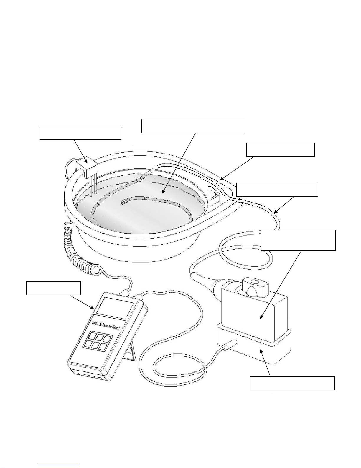
Typical electrical safety (leakage) testing of the diagnostic ultrasound transducer should
occur as part of the routine cleaning and disinfecting activity that is performed between
patient ultrasound procedures. The ultrasound transducer (see Item 5 in Figure 1) is
immersed in a basin (see Item 4 in Figure 1) containing conductive liquid (see Item 7 in
Figure 1) suitable for performing electrical safety tests. This liquid can be the routine
cleaning and disinfecting agent used, as long as it is suitably conductive to electrical
current flow. Cidexis an example of a widely used disinfecting agent used for cleaning
ultrasound transducers, and is suitably conductive for performing electrical safety tests
on transducers.
The ultrasound transducer is immersed in this conductive liquid and the electrical
connector of the transducer (see Item 6 in Figure 1) is attached to a suitable adapter (see
Item 3 in Figure 1) for that particular manufacturer and model transducer. This creates
one electrical “pole” for the test. The transducer adapter is then attached to the ULT-
2000 as shown in Figure 1. A special conductive probe (see Item 2 in Figure 1) is then
attached to the ULT-2000. This conductive probe is also immersed in the basin of
conductive liquid, creating the second electrical pole. The setup is now complete for the
testing of the connected transducer.
6
During testing, the transducer is subjected to a user selectable source voltage. This
voltage is typically set to the normal operating voltage of the transducer’s ultrasound
machine. In North America, the source voltage is typically set to 120 VAC @ 60 Hz. For
countries where the normal operating voltage is 230 VAC, the source voltage can be set
to this level, at either 50 or 60 Hz, as appropriate.
Figure 1
Typical Test Setup for ULT-2000
5 –Transducer (DUT)
4 –Test Basin
2 –Conductivity Probe
1 –ULT-2000
3 –Transducer Adapter
6 –Transducer
Electrical Connector
7-Conductive Liquid Medium

7
NOTICE –TESTING
CONDUCTIVE SURFACES SUCH AS METAL CARTS OR
TABLETOPS CAN CAUSE ERRONEOUS READINGS DUE TO
ALTERNATE LEAKAGE PATHS FROM TRANSDUCER
ADAPTERS, CABLES, ETC. ENSURE TEST IS DONE ON ANON-
CONDUCTIVE SURFACE FOR BEST RESULTS.

8
The ULT-2000 series completes four intermediate tests as part of the Full Test to fully
evaluate the integrity of an ultrasound probe. The following is the details of each test
step:
Source Voltage Test - The first step is to read the actual source (challenge) voltage that
will be applied during the testing to ensure that it is within range. If it is not, an alarm is
activated and the test is halted.
Self Test - The second step checks the Leakage Measuring Circuitry. A relay switches
to a dummy internal load. The source (challenge) voltage is then applied to this load. The
unit must correctly read the known leakage current. If it is not read correctly, an alarm is
activated and the test is halted.
Bath Conductivity Test –The third step tests the conductivity of the liquid in the test
basin. The ULT-2000 accomplishes this task quite easily and reports a simple PASS /
FAIL, or the actual numerical conductivity of the liquid (depending on the system
configuration). If the conductivity of the liquid is insufficient to perform a valid electrical
leakage current test, the ULT-2000 will report this and will not allow the probe test to be
performed.
Probe Leakage Test –The fourth step tests the electrical leakage of the ultrasound
transducer. The measured leakage current is compared to the selected upper and lower
limits. Again, the results of the test will be reported as a simple PASS / FAIL, or the actual
leakage current values. This step is only included when the user performs a Full Test.
TEST PROCESS
9
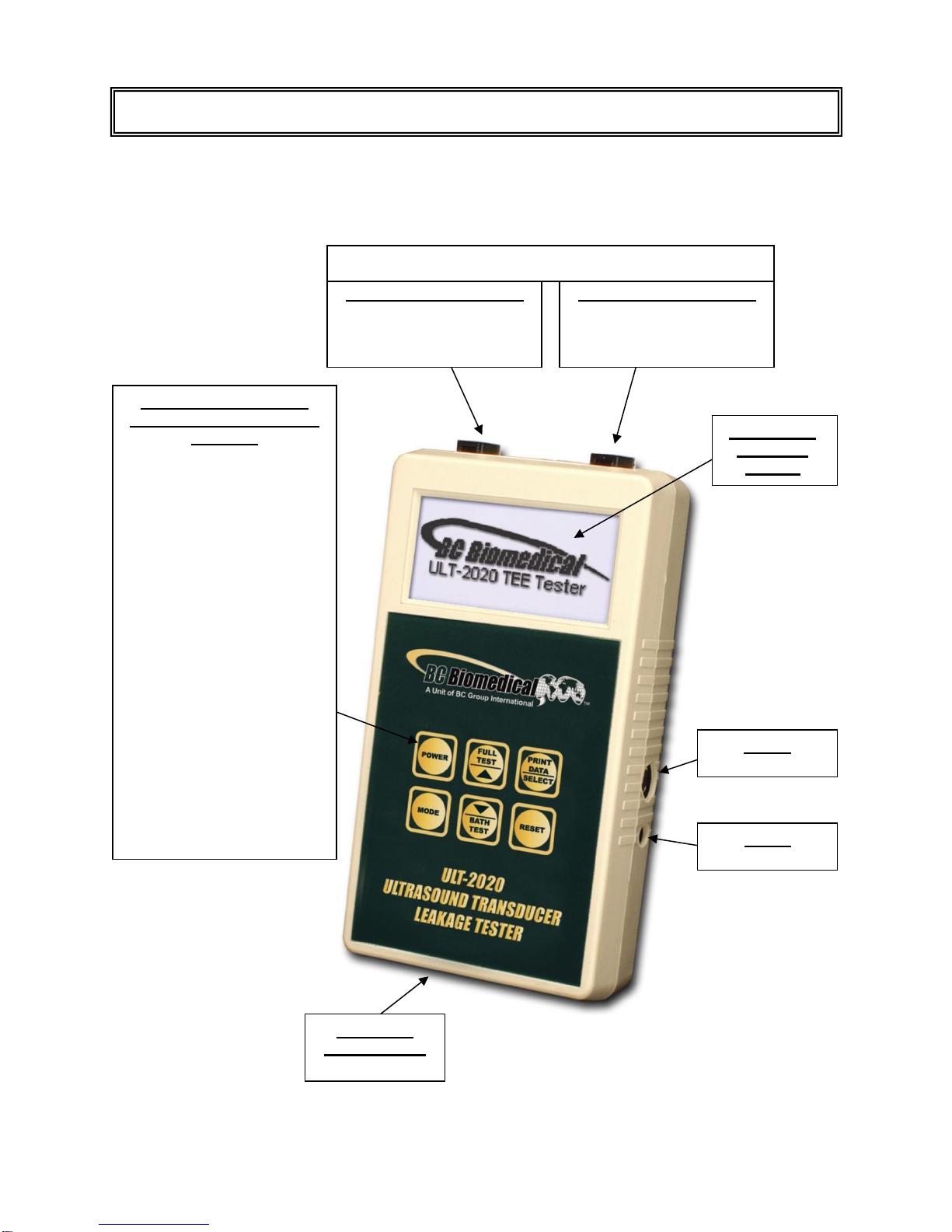
This section looks at the physical layout of the ULT-2000 Series and gives descriptions
of the elements.
Locking DUT Connector
–To ultrasound transducer
via Transducer Adapter
RS232
7 PIN Mini-Din
Power
2.1 mm Jack
6 Light Touch Keys for
Selecting Parameters and
Settings:
POWER
- Turns Unit On and Off
FULL TEST / UP
- Tests Conductivity and
Leakage
- Scrolls Through Selected
Parameter Options
SELECT / PRINT DATA
- Selects Next Available
Parameter
- Prints Data
MODE
- Changes Operating Mode
- Enters / Exits Setup Mode
BATH TEST / DOWN
- Tests Conductivity Only
- Scrolls Through Selected
Parameter Options
RESET
- Aborts Any Test
- Returns to Main Screen
9V Battery
Compartment
(Back)
Backlit LCD
Graphical
Display
Locking DUT Connector
–To conductive bath via
Dual Conductivity Probe
LAYOUT
The Locking DUT Connections are Interchangeable
–To conductive bath via Dual Conductivity Probe
10
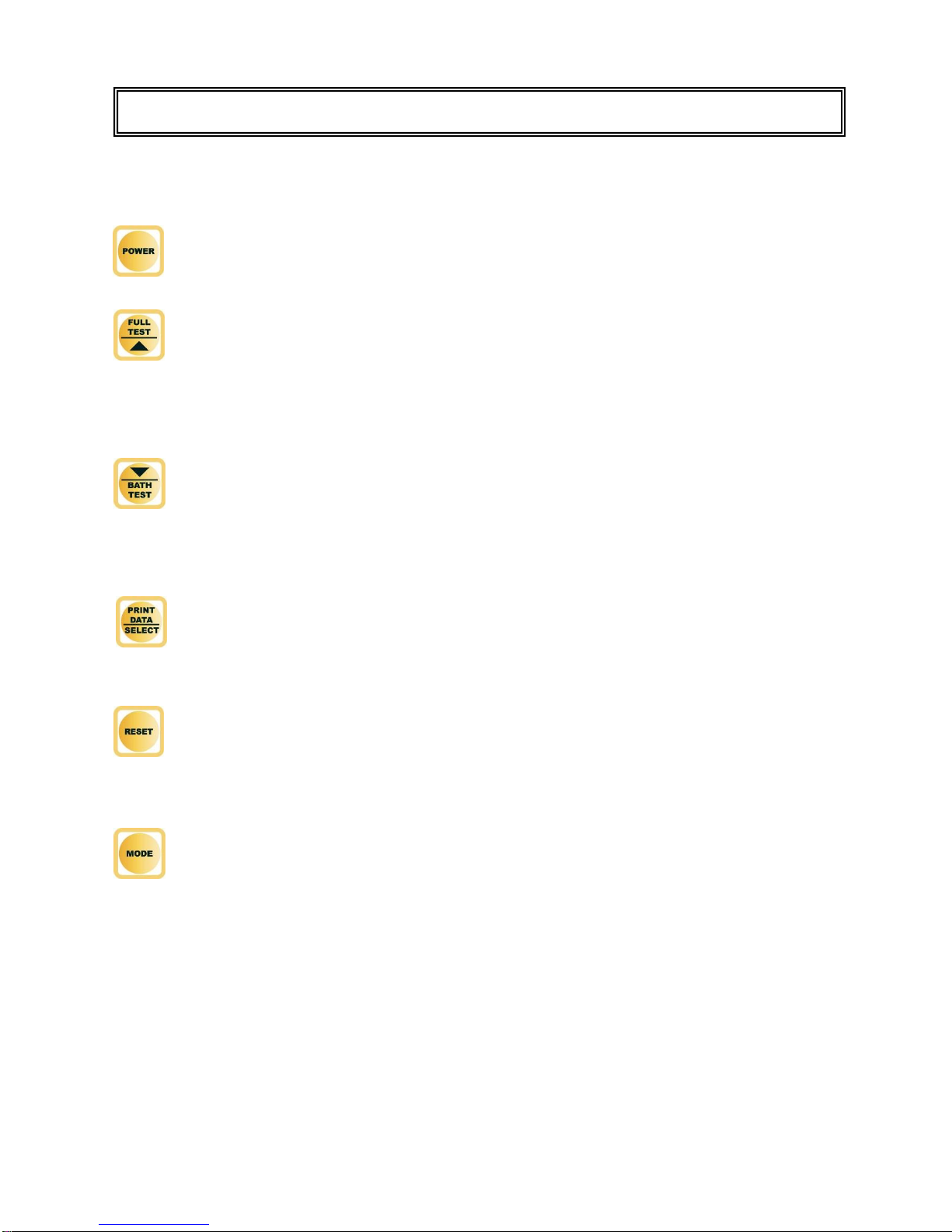
Six tactile-touch keys with audio feedback are provided for system operation:
–This key turns the unit on and off. The unit will initiate with the Main Screen.
–At the Main Screen, this key initiates the Full Test, which includes a Source
Voltage Test, a Self Test, a Bath Test, and a transducer Probe Test.
–All other screens, this key scrolls up through the selected
parameter options.
–At the Main Screen, this key initiates a conductivity test of the
conductive liquid medium in the bath.
–All other screens, this key scrolls down through the selected parameter options.
–At the Datalog Screen, this key prints the latest test results to the serial port.
–All other screens, this key selects the next available parameter.
–When not in a SETUP menu, this key resets the system to the main
screen.
–When in a SETUP menu, this key has no function.
–This key toggles the unit through operating modes. Pressing this key toggles
from the Main Screen, to the Meter Screen (ULT-2020 Only), to the Datalog
Screen (ULT-2020 only), and then to the Device Configuration Screen.
–Pressing and holding this key allows entry to the SETUP menus where system
configurations can be viewed and adjusted. When in a SETUP menu, this key
exits the SETUP menu and returns to the previously viewed screen. This also
saves the system settings to the internal EEPROM memory so they are
retained with the power turned off or battery removed.
KEYS
11
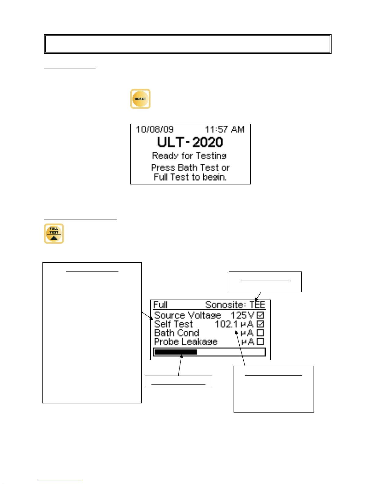
MAIN SCREEN –The main screen indicates that the ULT-2000 Series unit is initialized
and ready for testing. This screen displays after power-up initialization, and can be
accessed by pressing the key at any time other than during setup mode.
FULL TEST SCREEN –This screen is accessed from the Main Screen by pressing the
button. It displays Full Test information, measurements, and progress.
DUT Information
Manufacturer: Model
Progress Indicator
Full Test Process:
SOURCE VOLTAGE TEST
- verifies the voltage circuit to be
used during testing.
SELF TEST
- verifies that the ULT-2000
Series unit is working properly
before checking the DUT
BATH CONDUCTIVITY TEST
- ensures that the test fluid has
the proper level of electrical
conductivity needed for a valid
electrical leakage test.
PROBE LEAKAGE TEST
- measures the leakage current
of the DUT (changes to peak
current at the end of this test).
SCREENS
Test Measurements
Numerical values will not
appear if Test Mode is set
to “Pass/Fail”. See
System Configuration in
SETUP.

12
BATH TEST SCREEN –This screen is accessed from the Main Screen by pressing the
button. It displays Bath Test information, measurements, and progress.
TEST MESSAGES –Messages appear after each FULL or BATH test is completed.
TEST PASSED –This message indicates a successful test within the selected limits.
TEST FAILED –This message indicates a test failure, and provides failure details. The
example shown below indicates that the probe leakage current is above the selected
upper limit.
Bath Test Process:
SOURCE VOLTAGE TEST
- verifies the voltage circuit to be
used during testing.
SELF TEST
- verifies that the ULT-2000
Series unit is working properly
before checking the DUT
BATH CONDUCTIVITY TEST
- ensures that the test fluid has
the proper level of electrical
conductivity needed for a valid
electrical leakage test.
DUT Information
Manufacturer: Model
Progress Indicator
Test Measurements
Numerical values will not
appear if Test Mode is set
to “Pass/Fail”. See
System Configuration in
SETUP.
Other manuals for ULT-2000 series
2
Table of contents
Other BC Biomedical Test Equipment manuals


