Bosch BAT 125 User manual

BAT 125
en
Original instructions
Battery Tester
es
Manual original
Comprobadores de batarías
pt
Manual original
Aparelho de teste para baterias
ja
取扱説明書の原本
スターター バッテリー用テスター
zh
原始的指南
用于 起动蓄电池的测试仪


1 689 989 125 2013-09-09| Robert Bosch GmbH
4 | BAT 125 | Symbols useden
Contents English
1. Symbols used 4
1.1 In the documentation 4
1.1.1 Warning notices -
Structure and meaning 4
1.1.2 Symbols in this documentation 4
1.2 On the product 4
2. User information 5
2.1 Important notes 5
2.2 Safety instructions 5
2.3 Intended use 5
3. User Interface 5
3.1 Scope of delivery 5
3.2 Product description 5
3.3 Function of the keys 5
3.4 Switch on 5
3.5 Switch off 5
3.6 Menu 6
3.7 Special accessory 6
4. Perform Test 6
4.1 Test Preparations 6
4.2 Connecting BAT 125 6
4.2.1 Directly on battery posts (TOP POST) 6
4.2.2 On side battery posts via lead post
adapter (SIDE POST) 6
4.2.3 On jump-start posts
(JUMP START POST) 7
4.3 Battery Test 7
4.4 Battery Test Results 7
4.5 Starter System Test 8
4.6 Starter System Test Results 8
4.7 Charging System Test 8
4.8 Charging System Test Results 9
4.9 Additional Test Messages 9
5. Maintenance & Troubleshooting 10
5.1 Cleaning 10
5.2 Service Parts / Parts Subject to Wear 10
5.3 Changing the Printer Paper 10
5.4 Changing The Cable Assembly 11
5.5 Replacing the Battery 11
5.6 Troubleshooting the Display 11
5.7 Troubleshooting the Printer 12
5.8 Disposal 12
6. Technical data 12
6.1 Battery-Test and Voltmeter 12
6.2 Printer Paper 12
1. Symbols used
1.1 In the documentation
1.1.1 Warning notices - Structure and meaning
Warning notices warn of dangers to the user or people in
the vicinity. Warning notices also indicate the consequenc-
es of the hazard as well as preventive action. Warning no-
tices have the following structure:
Warning
symbol
KEY WORD – Nature and source of hazard!
Consequences of hazard in the event of fail-
ure to observe action and information given.
¶Hazard prevention action and information.
The key word indicates the likelihood of occurrence and
the severity of the hazard in the event of non-observance:
Key word Probability of
occurrence
Severity of danger if in-
structions not observed
DANGER Immediate impend-
ing danger
Death or severe injury
WARNING Possible impending
danger
Death or severe injury
CAUTION Possible dangerous
situation
Minor injury
1.1.2 Symbols in this documentation
Symbol Designation Explanation
!Attention Warns about possible property damage.
iInformation Practical hints and other
useful information.
1.
2.
Multi-step
operation
Instruction consisting of several steps.
eOne-step
operation
Instruction consisting of one step.
Intermediate
result
An instruction produces a visible inter-
mediate result.
"Final result There is a visible final result on com-
pletion of the instruction.
1.2 On the product
!Observe all warning notices on products and ensure
they remain legible.

1 689 989 125 2013-09-09|Robert Bosch GmbH
User information | BAT 125 | 5 en
2. User information
2.1 Important notes
Important information on copyright, liability and warran-
ty provisions, as well as on equipment users and com-
pany obligations, can be found in the separate manual
"Important notes on and safety instructions for Bosch
Battery Test Equipment". These instructions must be
carefully studied prior to start-up, connection and opera-
tion of the BAT 125 and must always be heeded.
2.2 Safety instructions
All the pertinent safety instructions can be found in
the separate manual "Important notes on and safety
instructions for Bosch Battery Test Equipment". These
instructions must be carefully studied prior to start-up,
connection and operation of the BAT 125 and must al-
ways be heeded.
2.3 Intended use
The portable and network-independent
BAT 125
was
developed for mobile use. It is used for testing of 6 volt
and 12 volt starter batteries (lead-acid batteries, AGM
flat plate batteries, AGM spiral batteries, gel batteries)
and inspection of 12 volt and 24 volt starting systems
and charging systems for cars, water crafts, motor-
cycles and light commercial vehicles. You can check the
batteries either in the vehicle while installed or when
removed. It displays the test results and is equipped
with a printer via which the customer is provided with a
printout of the results.
Additional features include the ability to:
RTesting of batteries at a rated cold start current
(CCA) of 100 A to 2000 A
Rdetect bad cells
Rprotect against reverse polarity
Rtest discharged batteries
Rtest multiple rating systems
(EN, EN2, DIN, SAE, IEC, JIS)
Ra multi-lingual user interface
iFor battery assessment, the
BAT 125
must be provid-
ed with the cold start current (CCA) in amperes and
the battery standard (EN, EN2, DIN, SAE, IEC, JIS)
as reference values. Correct entry of these reference
values is a prerequisite for accurate battery testing.
3. User Interface
3.1 Scope of delivery
Designation Item number
BAT 125 –
Paper –
Connecting cable 1,2 m 1 684 465 624
Operating Instructions 1 689 989 125
3.2 Product description
Fig. 1: BAT 125
1 Printer
2 Display
3 POWER to switch BAT 125 on/off and function key MENU
4 Cover for current probe connection socket
5 Connecting cable with terminals for the battery
6 USB interface (customer service only)
3.3 Function of the keys
Symbol Name Function
ARROWS Scroll to menu options and print the
test results.
ARROWS Choose test parameters
EENTER Make selections or save changes
MENU Access the Main Menu options
3.4 Switch on
¶Press .
iIf the display does not turn on please see chap. 6.6
3.5 Switch off
1. Go to Main Menu.
2. Disconnect BAT 125 from the battery.
3. Press .
iIf BAT 125 is connected to the battery, you can not
switch off.

1 689 989 125 2013-09-09| Robert Bosch GmbH
6 | BAT 125 | Perform Testen
3.6 Menu
1. Press Qto access the Menu.
2. Use the or to highlight the line you want to
edit.
3. Press Eto edit the line or save your changes.
4. Use
or
to select the function to use or edit.
5. Press Eto move to the next location.
6. Press Qto return to the Menu.
Option Description
Perform Test Begin the Battery and System Test pro-
cedure.
Voltmeter Start the test battery voltage.
View / Print Display the previous test result. Press
the button to print the results.
Counter Clear or display battery and system test
by results.
Settings Customize tool options to fit your needs.
Language Select a language for the tester.
Default: English
Set Address Create a header for your printed test re-
sults with your business location infor-
mation.
Set Time Select 24-hour or AM/PM and set the
time.
Default: AM/PM
Set Date Select the date format and date.
Default: MM/DD/YYYY
Contrast Adjust the contrast setting of the tes-
ter display.
Default: 23
Temperature Units Select the temperature units Degrees °F
or Degrees °C.
Default: Degrees F
Amp Clamp Prompt for Amp Clamp availability.
Version Info Lists the software version, software ver-
sion date, and serial number.
Update Update the tester's internal operating
software.
3.7 Special accessory
Designation Item number
Current probe 1 681 354 034
4. Perform Test
4.1 Test Preparations
!If performing the battery test in a vehicle, ensure
that
$all additional loads are deactivated,
$the key is not in the ignition,
$all doors are closed,
$measuring is not carried out by or with steel
bolts.
iBefore connecting the tester, clean the battery posts
or side terminals with a wire brush and a mixture of
baking soda and water.
4.2 Connecting BAT 125
!For a proper connection, rock the clamps back and
forth. The tester requires that both sides of each
clamp be firmly connected before testing. A poor
connection will produce a CHECK CONNECTION or
WIGGLE CLAMPS message. If the message appears,
clean the terminals and reconnect the clamps.
iThe preferred test position is at the battery termi-
nals. If the battery is not accessible, you may test at
the jumper post; however, the available power mea-
surement may be lower than the actual value.
4.2.1 Directly on battery posts (TOP POST)
1. Connect the red clamp directly to the positive post
(+).
2. Connect the black clamp directly to the negative
post (–).
4.2.2 On side battery posts via lead post adapter
(SIDE POST)
!Test results will be inaccurate, if there is no
$lead post adapter or
$worn or dirty lead post adapters are used.
!Tighten the lead post adapter with an adjustable
wrench by a max. of ¼ turn.
1. Connect the red clamp via the lead post adapter
(available from specialist stores) on the side positive
post (+).
2. Connect the black clamp via the lead post adapter
(available from specialist stores) on the side nega-
tive post (–).

1 689 989 125 2013-09-09|Robert Bosch GmbH
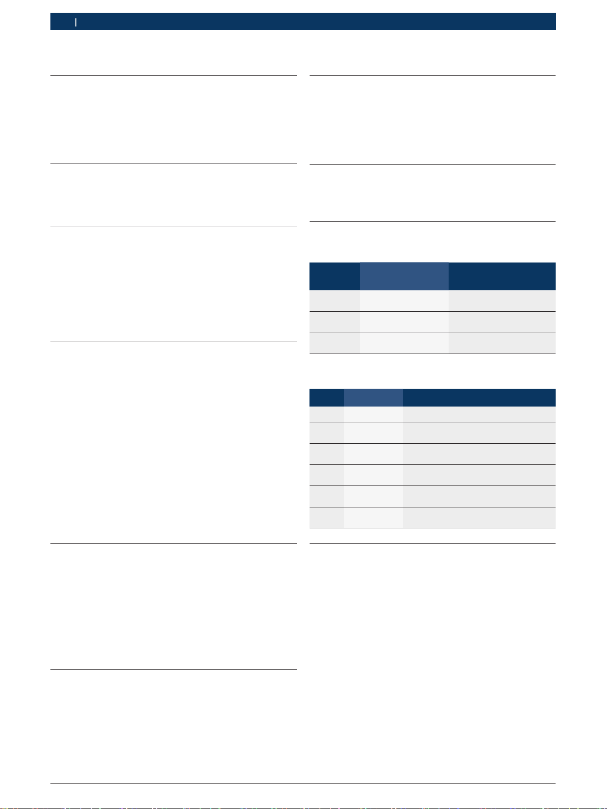
Perform Test | BAT 125 | 7 en
4.2.3 On jump-start posts (JUMP START POST)
1. Connect the red clamp to the positive jump-start
post (+).
2. Connect the black clamp to the negative jump-start
post (–).
4.3 Battery Test
1. BAT. LOCATION
Scroll to and select IN VEHICLE or OUT OF VEHICLE
for a battery not connected to a vehicle.
iFollowing an "IN VEHICLE" test you will be prompted
to test the starting and charging systems.
!The performance of the starting and charging sys-
tems depends on the battery’s condition. It is impor-
tant that the battery is good and fully charged before
any further system testing.
2. POST TYPE (In-Vehicle only)
Scroll to TOP POST, SIDE POST or JUMP START
POST where applicable.
iBattery assessment (refer to Section 4.4) is only
performed if the "BATTERY POST AT TOP" option is
selected.
3. APPLICATION
Scroll to and select AUTOMOTIVE or MOTORCYCLE.
iFor MOTORCYCLE select "BEFORE DELIVERY" or
"IN SERVICE" and scroll to the correct BATTERY
NUMBER and press Eto begin the testing process.
4. BATTERY STANDARD
Scroll to and select STANDARD, AGM FLAT PLATE,
AGM SPIRAL, or GEL where applicable.
5. BATTERY’S RATING SYSTEM
Select the battery standard to be applied.
Standard
Description Range
CA Cranking Amps 100-1200
CCA Cold Cranking Amps 100-1200
MCA Marine Cranking Amps 100-1200
EN Europa-Norm 100-2000
EN2 Europa-Norm 2 100-2000
DIN Deutsche Industrie-Norm,
German industry norm
100-1200
SAE Society of Automotive Engineers, the
European labeling of CCA
100-2000
IEC International Electrotechnical
Commission
100-1200
JIS
Japanese Industrial Standard, shown on
a battery as a combination of numbers
and letters.
26A17 thru
245H52
iFor JIS scroll to the correct BATTERY NUMBER and
press Eto begin the testing process.
6. BATTERY RATING
Scroll to and select the numeric rating units (cold start
current in passenger cars and water crafts). Hold down
the
or
to increase the scrolling speed.
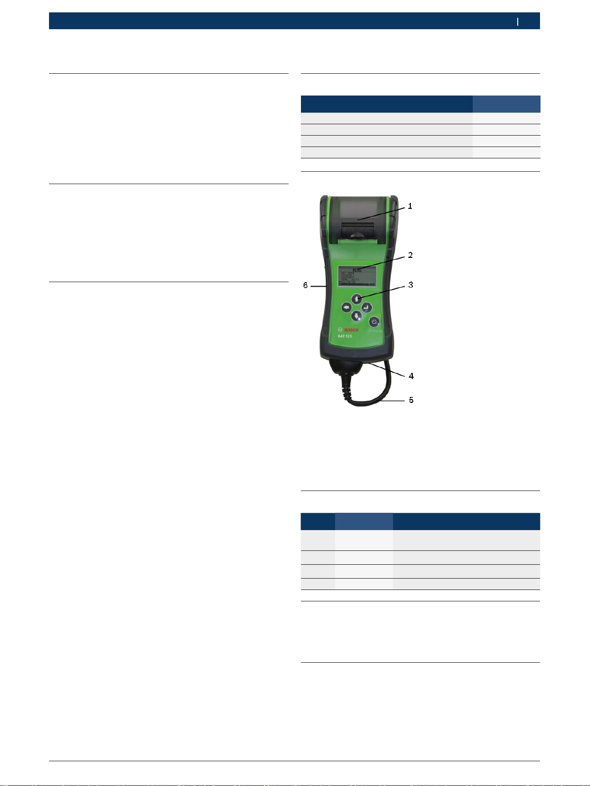
7. Press Eto start test.
"After several seconds the tester displays the decision
on the battery’s condition and the measured voltage.
The tester also displays your selected battery rating
and the rating units.
iTo view the State of Health of the battery, press to
print out the test results including the State of Health
graph.
4.4 Battery Test Results
!The
BAT 125
retains the results of the last test only. When
you start a new test, the last results are overwritten.
iPress Eto proceed with the starter test, to print
the test results or MENU to return to the Menu.
Message Action to be taken
GOOD BATTERY 1) Return the battery to service.
GOOD-RECHARGE 1) Fully charge the battery and return it to
service.
CHARGE & RETEST 1)
Fully charge the battery and retest. Failure
to fully charge the battery before retesting
may cause inaccurate results. If CHARGE
& RETEST appears again after you fully
charge the battery, replace the battery.
REPLACE BATTERY. 1) Replace the battery and retest. A RE-
PLACE BATTERY result may also mean
a poor connection between the battery
cables and the battery. After discon-
necting the battery cables, retest the
battery using the out-of-vehicle test be-
fore replacing it.
BAD CELL-REPLACE Replace the battery and retest.
24 VOLT SYSTEM 24-volt system detected. Disconnect
batteries and test individually.
READY TO INSTALL Battery has just been activated and is
ready to install in vehicle
NEEDS CHARGE 1)
Fully charge battery and retest using BE-
FORE DELIVERY.
Failure to fully charge the battery be-
fore retesting may cause false readings.
SIDE POST Test data was inconclusive using the
side post. Retest using side post adapt-
ers.
JUMP START POST Data was inconclusive using the Remote
post. Retest at the battery terminals.
1) The battery is only assessed if the "BATTERY POST AT TOP"
option is selected.

1 689 989 125 2013-09-09| Robert Bosch GmbH
8 | BAT 125 | Perform Testen
iFor an in-vehicle test, the display alternates between
the test results and the message “PRESS EFOR
STARTER TEST".
4.5 Starter System Test
!Before starting the test, inspect the alternator drive
belt. A belt that is glazed or worn, or lacks the
proper tension, will prevent the engine from achiev-
ing the rpm levels needed for the test.
iOnce you have completed an in-vehicle test, the dis-
play alternates between the battery test results and
the message PRESS EFOR STARTER TEST.
1. Press the Ebutton to proceed with the starter test.
iIf an Amp Clamp is being used, follow the on screen
procedure to zero it out before proceeding with the
test.
2. Start the engine when prompted.
3. The tester displays the Starter System cranking volt-
age and cranking time in milliseconds.
4.6 Starter System Test Results
iPress
E
to proceed with the charging system test,
press
to print the test results, press
MENU
to
return to the Menu.
Message Action to be taken
CRANKING NORMAL The starter voltage is normal and the
battery is fully charged.
LOW VOLTAGE The starter voltage is low and the bat-
tery is fully charged.
CHARGE BATTERY The starter voltage is low and the bat-
tery is discharged. Fully charge the bat-
tery and repeat the starter system test.
REPLACE BATTERY Battery must be replaced before the
starting system can be tested.
NO START No vehicle start detected.
CRANKING SKIPPED A start was not detected.
SIDE POST Test data was inconclusive using the
side post. Retest using side post adapt-
ers.
JUMP START POST Data was inconclusive using the Re-
mote post. Retest at the battery termi-
nals.
iFor an in-vehicle test, the display alternates between
the test results and the message PRESS EFOR
CHARGING TEST.
4.7 Charging System Test
iOnce you have completed an in-vehicle test and the
starteter test, the display alternates between the
battery test results and the message PRESS E
FOR CHARGING TEST. Press the Ebutton to pro-
ceed with the charging test.
Following the on-screen prompts:
1. Rev the engine.
2. Turn on high beams headlights and the blower fan.
3. Rev engine with loads on.
4. Idle engine and turn off loads.
5. The Charging System decision is displayed at the
end of the procedure.
6. Press to print the test results or Qto return to the
Menu.

1 689 989 125 2013-09-09|Robert Bosch GmbH
Perform Test | BAT 125 | 9 en
4.8 Charging System Test Results
iPress the to print the test results or MENU/POWER to return to the Options 1Menu.
Message Interpretation Action to be taken
NO PROBLEMS System is showing normal
output from the alternator.
–
NO OUTPUT No alternator output de-
tected.
RCheck all connections to and from the alternator, especially the connection to
the battery. If the connection is loose or heavily corroded, clean or replace the
cable and retest.
RIf the belts and connections are in good working condition, replace the alterna-
tor. (Older vehicles use external voltage regulators, which may require only re-
placement of the voltage regulator.)
LOW OUTPUT Alternator not providing
sufficient current to pow-
er the system's electrical
loads and to charge the
battery.
RCheck the belts to ensure the alternator is rotating with the engine running. Re-
place broken or slipping belts and retest.
RCheck the connections from the alternator to the battery. If the connection is
loose or heavily corroded, clean or replace the cable and retest.
HIGH OUTPUT Alternator voltage output
exceeds the normal limits.
RMake sure there are no loose connections and the ground connection is normal.
If there are no connection problems, replace the regulator. Most alternators
have a built-in regulator that requires replacing the alternator. In older vehicles
that use external voltage regulators, you may need to replace only the voltage
regulator.
EXCESSIVE RIPPLE Excessive AC ripple de-
tected.
One or more diodes in the alternator is not functioning or there is stator damage.
CHARGE BATTERY The starter voltage is low
and the battery is dis-
charged.
Fully charge the battery and repeat the starter system test.
REPLACE BATTERY If the battery test result
was REPLACE or BAD
CELL.
The battery must be replaced before testing the starter.
SIDE POST Test data was inconclusive
using the side post.
Retest using side post adapters.
REMOTE POST Data was inconclusive us-
ing the Remote post.
Retest at the battery terminals.
iSee “Maintenance & Troubleshooting” in this manual for more information about the printer.
4.9 Additional Test Messages
For a more decisive result, the tester may prompt you for additional information. The messages in the following table
may appear before the tester can display a result.
Test Message Action to be taken
BAT. TEMPERATURE Select ambient temperature above or below 0˚C (32˚F).
CHARGE STATE Select before or after battery has been charged.
SURFACE CHARGE DETECTED Remove the surface charge before it begins testing. Testing will resume after charge has been re-
moved.
CHECK CONNECTION One or both clamps are not making proper contact with the battery terminals.
ENGINE REV NOT
DETECTED PRESS
WHILE REVVING
Tester has not detected an increase in engine rpm
REVERSE CONNECTION Clamps are connected in the wrong polarity: positive to negative or negative to positive.
SYSTEM NOISE CHECK LOADS Only with BATT. LOCATION INSIDE VEHICLE. BAT 125 has recognized active loads in the vehicle. En-
sure that all loads in the vehicle are deactivated, including opened doors and the ignition switch.
UNSTABLE BATTERY Out-of-vehicle. Weak battery, should be charged and retested.
WIGGLE CLAMPS Clamps are not making good contact with battery terminals

1 689 989 125 2013-09-09| Robert Bosch GmbH
10 | BAT 125 | Maintenance & Troubleshootingen
5. Maintenance & Trouble-
shooting
5.1 Cleaning
The housing and the display of the BAT 125 may only be
cleaned using soft cloths and neutral cleaning agents.
Do not use any abrasive cleaners or coarse workshop
cleaning rags.
5.2 Service Parts / Parts Subject to Wear
Designation Ordering number
Connecting cable with terminals for the
battery <)
1 684 465 624
Printer paper <) (1 roll)
(Minimum order 5 rolls)
1 681 420 028
<) wearing part
5.3 Changing the Printer Paper
iThe integrated printer only uses thermal paper in a
roll with the dimensions 57 mm x 25.9 mm.
1. Unlock the printer door gently but firmly lifting up on
the release lever.
2. Remove the empty paper roll hub.
Fig. 2: Printer view
1 Paper Compartment
2 Paper Sensor
3 Release Lever
3. Place a new roll of paper in the compartment.
4. Pull the paper forward so that it extends past the
serrated edge of the paper slot.
Fig. 3: Paper feeds from underneath the roll
5. Close the door and make sure the lever locks securely.

1 689 989 125 2013-09-09|Robert Bosch GmbH
Maintenance & Troubleshooting | BAT 125 | 11 en
5.4 Changing The Cable Assembly
1. Identify the circled screw on the back of the tester.
2. Remove the screw.
3. Grasp the housing and firmly pull the cable assembly
from housing.
4. To attach a new cable, align the cable and tester
housings and push together.
5. Insert the screw and tighten.
5.5 Replacing the Battery
This BAT 125 is subject to European guide-
lines 2002/96/EG (WEEE).
Old electrical and electronic devices, includ-
ing cables and accessories or batteries must
be disposed of separate to household waste.
¶Please use the return and collection sys-
tems in place for disposal in your area.
¶Damage to the environment and hazards
to personal health are prevented by prop-
erly disposing of BAT 125.
The BAT 125 can test down to 5.5 volts when the unit’s
internal batteries are not functioning. The tester dis-
plays LOW INTERNAL AA BATTERIES, REPLACE
AA BATTERIES SOON! when the internal AA batteries
need to be replaced.
iSetup information will be retained while you change
the internal batteries.
Use the following procedure to remove and replace the
internal AA batteries:
1. Turn BAT 125 face down.
2. Remove the screw securing the battery compartment
cover using a small Phillips screwdriver.
3. Lift the door off and remove the discharged battery.
4. Insert fresh AA batteries making sure the positive
and negative terminals are positioned correctly.
5. Reposition the cover and tighten the screw.
5.6 Troubleshooting the Display
If the display does not turn on:
1. Press and hold MENU for minimum 2 seconds.
2. Check the connection to the vehicle battery.
3. The vehicle battery may be too low (below 1 volt) to
power the analyzer. Fully charge the battery and retest.
4. The analyzer’s AA batteries may need to be replaced.
(alkaline recommended).
5. If the analyzer does not power on when you press
and hold Q, replace the AA batteries.

1 689 989 125 2013-09-09| Robert Bosch GmbH
12 | BAT 125 | Maintenance & Troubleshootingen
5.8 Disposal
This BAT 125 is subject to European guide-
lines 2002/96/EG (WEEE).
Old electrical and electronic devices, includ-
ingcables and accessories or batteries must
be disposed of separate to household waste.
¶Please use the return and collection sys-
tems in place for disposal in your area.
¶Damage to the environment and hazards
to personal health are prevented by prop-
erly disposing of BAT 125.
6. Technical data
Function / Range Value
Function range 0 °C – 50 °C
32 °F – 122 °F
Accuracy range 0 °C – 40 °C
32 °F – 104 °F
Workplace-related
noise-emission value (Lpa)
< 70 dB(A)
6.1 Battery-Test and Voltmeter
Function / Range Value
Operating voltage 8 V – 16 V
Operating current without printer 0,4 A
Entry range of Cold Start Current 50 A - 1550 A
Battery standards CA, CCA, MCA,
DIN, EN, EN2,
IEC, JIS, SAE
6.2 Printer Paper
Function / Range Value
Maximum storage period by storage in
the dark in years
< 5
Maximum storage temperature 30 °C
86 °F
Maximum storage humidity <60 %
5.7 Troubleshooting the Printer
!If the BAT 125 is not connected to a 12-volt battery
with at least 11.5 volts of
power or the paper sensor
does not detect paper in the compartment during the
print process
Message Action to be taken
BATTERY POWER TOO
LOW TO USE PRINT-
ER. CONNECT TO FULLY
CHARGED BATTERY
11.50 TO 16.00V
To print, the tester must be properly
connected to a vehicle battery hav-
ing at least 9 volts.
RConnect to a vehicle battery with
enough voltage to enable printing.
RMake sure that the clamps are
connected properly: red clamp to
the positive (+) terminal and the
black clamp to the negative (-) ter-
minal.
RCheck that both sides of the
clamps are making contact with
the terminals.
CONNECT TO
12V BATTERY
Tester is not connected to the bat-
tery
LOW INTERNAL AA BAT-
TERIES. REPLACE AA
BATTERIES SOON!
Internal AA batteries are low and
need to be replaced. See "Mainte-
nance & Troubleshooting" section.
NON 12 VOLT SYSTEM
DETECTED
System being tested is not 12-volts.
PRINTER DOOR OPEN.
CLOSE DOOR AND TRY
TO PRINT AGAIN
Check that the door covering the
printer paper is properly closed and
latched.
PRINTER OUT OF PAPER
REPLACE WITH THERMAL
PRINTER PAPER.
2.5 IN. DIA. MAX
2.25 IN. WIDE MAX
Printer is out of thermal paper.
RVerify that the paper is inserted
correctly.
RInsert a new roll of paper.
RVerify that the paper sensor is
clean and undamaged
QC DATA MEMORY FULL
PRINT RESULTS OR
CLEAR MEMORY.
QC mode memory is full. Select
QC mode from the Options Menu to
clear the memory.

1 689 989 125 2013-09-09|Robert Bosch GmbH
Símbolos empleados | BAT 125 | 13 es
Índice español
1. Símbolos empleados 13
1.1 En la documentación 13
1.1.1 Advertencias: estructura y significado 13
1.1.2 Símbolos en esta documentación 13
1.2 En el producto 13
2. Indicaciones para el usuario 14
2.1 Indicaciones importantes 14
2.2 Indicaciones de seguridad 14
2.3 Uso previsto 14
3. Interfaz de usuario 14
3.1 Volumen de suministro 14
3.2 Descripción del producto 14
3.3 Función de las teclas 14
3.4 Encender 14
3.5 Apagar 15
3.6 Menú 15
3.7 Accesorios especiales 15
4. Ejecución de la prueba 15
4.1 Preparación de la prueba 15
4.2 Conexión del BAT 125 15
4.2.1 Directamente en los polos de
la batería (BORNE SUPERIOR) 15
4.2.2 En los polos de la batería laterales
mediante adaptadores de polo
de plomo (BORNE LATERAL) 15
4.2.3 En polos para arranque mediante
cables de puente (BORNE ARRANQUE) 16
4.3 Prueba de batería 16
4.4 Resultados de la prueba de batería 16
4.5 Prueba del sistema de arranque 17
4.6 Resultados de la prueba
del sistema de arranque 17
4.7 Prueba del sistema de carga 17
4.8 Resultados de la prueba del sistema de carga 18
4.9 Mensajes de prueba adicionales 18
5. Mantenimiento y solución de problemas 19
5.1 Limpieza 19
5.2 Piezas de mantenimiento/piezas sujetas
a desgaste 19
5.3 Cambio del papel de la impresora 19
5.4 Cambio del conjunto del cable 19
5.5 Cambio de batería 20
5.6 Solución de problemas de la pantalla 20
5.7 Solución de problemas de la impresora 21
5.8 Eliminación 21
6. Datos técnicos 21
6.1 Prueba de batería y voltímetro 21
6.2 Papel de impresora 21
1. Símbolos empleados
1.1 En la documentación
1.1.1 Advertencias: estructura y significado
Las indicaciones de advertencia advierten de peligros
para el usuario o las personas circundantes. Adicional-
mente, las indicaciones de advertencia describen las
consecuencias del peligro y las medidas para evitarlo. Las
indicaciones de advertencia tienen la siguiente estructura:
Símbolo de
advertencia
PALABRA CLAVE – Tipo y fuente del peligro!
Consecuencias del peligro si no se tienen
en cuenta las medidas e indicaciones
mostradas.
¶Medidas e indicaciones de prevención
del peligro.
La palabra clave indica la probabilidad de ocurrencia
del peligro, así como la gravedad del mismo en caso de
inobservancia:
Palabra clave Probabilidad de
ocurrencia
Peligro grave en caso de
pasarse por alto
PELIGRO Peligro inmediato Muerte o lesiones físicas
graves
ADVERTENCIA Peligro amena-
zante
Muerte o lesiones físicas
graves
ATENCIÓN Posible situación
peligrosa
Lesiones físicas leves
1.1.2 Símbolos en esta documentación
Sím-
bolo
Denominación Significado
!Atención Advierte de posibles daños materiales.
iInformación Indicaciones de la aplicación y otras
informaciones útiles
1.
2.
Acción de
varios pasos
Solicitud de acción compuesta
de varios pasos
eAcción de un
solo paso
Solicitud de acción compuesta de
un solo paso
Resultado
intermedio
Dentro de una solicitud de acción se
puede ver un resultado intermedio.
"Resultado final Al final de una solicitud de acción se
puede ver el resultado final.
1.2 En el producto
!Tenga en cuenta todas las indicaciones de adverten-
cia en los productos y manténgalas bien legibles.

1 689 989 125 2013-09-09| Robert Bosch GmbH
14 | BAT 125 | Indicaciones para el usuarioes
2. Indicaciones para el usuario
2.1 Indicaciones importantes
Encontrará indicaciones importantes relativas al acuer-
do sobre los derechos de autor, la responsabilidad, la
garantía, el grupo de usuarios y las obligaciones de la
empresa, en las instrucciones separadas "Indicaciones
importantes e indicaciones de seguridad para Bosch
Battery Test Equipment". Es obligatorio prestarles aten-
ción y leerlas cuidadosamente antes de la puesta en
funcionamiento, la conexión y el manejo del BAT 125.
2.2 Indicaciones de seguridad
Encontrará todas las indicaciones de seguridad
en las instrucciones separadas "Indicaciones im-
portantes e indicaciones de seguridad para Bosch
Battery Test Equipment". Es obligatorio prestarles aten-
ción y leerlas cuidadosamente antes de la puesta en
funcionamiento, la conexión y el manejo del BAT 125.
2.3 Uso previsto
El BAT 125 portátil y autónomo, desarrollado para
aplicaciones móviles, se utiliza para probar baterías de
arranque de 6 V y 12 V (baterías con ácido, baterías
AGM de placas planas, baterías AGM espiral, baterías
de gel), así como para examinar sistemas de arranque
de 12 V y 24 V y sistemas de carga en turismos, embar-
caciones, motocicletas y vehículos industriales ligeros.
Las baterías se pueden comprobar tanto montadas en
el vehículo como también desmontadas. Muestra los re-
sultados de la prueba y está provisto de una impresora
que proporciona al cliente una copia de los resultados.
Entre las funciones adicionales se incluyen la capacidad
para:
RComprobación de las baterías con una corriente de
arranque en frío nominal (CCA) de 100 A hasta 2000A
Rdetectar pilas malas
Rproteger contra polaridad inversa
Rprobar baterías descargadas
Rprobar múltiples normas
(EN, EN2, DIN, SAE, IEC, JIS)
Rvisualizar la interfaz de usuario en múltiples idiomas
incluyendo:
iPara la evaluación del estado de una batería, el
BAT 125 necesita conocer la corriente de arranque en
frío (CCA) en amperios y la norma de baterías (EN,
EN2, DIN, SAE, IEC, JIS) como valores de referencia.
La introducción correcta de estos valores de referen-
cia es la condición imprescindible para una compro-
bación de la batería con resultados relevantes.
3. Interfaz de usuario
3.1 Volumen de suministro
Denominación Número de pedido
BAT 125 –
Papel –
Cable de conexión de 1,2 m 1 684 465 624
Instrucciones de servicio 1 689 989 125
3.2 Descripción del producto
Fig. 1: BAT 125
1 Impresora
2 Pantalla
3 INTERRUPTOR para encender/apagar el BAT 125
y tecla de función MENÚ
4 Cubierta casquillo de empalme de las pinzas de corriente
5 Cable de conexión con terminales para la batería
6 Puerto USB (sólo para el servicio postventa)
3.3 Función de las teclas
Símbo-
lo
Nombre Función
FLECHAS Desplazarse por las opciones de menú
e imprimir los resultados de la prueba
FLECHAS Eligir los parámetros de la prueba
EINTRO Hacer selecciones o guardar
los cambios
MENÚ Acceder a las opciones del menú
principal
3.4 Encender
¶Pulse .
iSi la pantalla no se enciende, véase cap. 6.6.

1 689 989 125 2013-09-09|Robert Bosch GmbH
Interfaz de usuario | BAT 125 | 15 es
4. Ejecución de la prueba
4.1 Preparación de la prueba
!Si se efectúa la prueba de batería en el vehículo,
asegurarse de que
$todos los accesorios estén apagados,
$la llave de contacto no esté insertada,
$todas las puertas estén cerradas y
$la medición no se lleve a cabo en o con tornillos
de acero.
iAntes de conectar el probador, limpiar los bornes de
la batería o terminales laterales con un cepillo metá-
lico y una mezcla de bicarbonato de sodio y agua.
4.2 Conexión del BAT 125
!Para verificar una correcta conexión, mover las
pinzas de un lado a otro. Ambos lados de cada pinza
deben estar conectados de manera firme antes de
ejecutar la prueba. Una conexión incorrecta produ-
cirá el mensaje VERIFICAR CONEXIÓN u HOLGU-
RA DE PINZAS. Si aparece el mensaje, limpie los
terminales y reconecte las pinzas.
iLa posición de comprobación preferida es en los ter-
minales de la batería. Si la batería no es accesible,
se puede probar en el borne arranque a puente; sin
embargo, la medición de potencias disponible puede
ser inferior al valor actual.
4.2.1 Directamente en los polos de la batería
(BORNE SUPERIOR)
1. Conectar la abrazadera roja directamente en el polo
positivo (+).
2. Conectar la abrazadera negra directamente en el
polo negativo (–).
4.2.2 En los polos de la batería laterales median-
te adaptadores de polo de plomo (BORNE
LATERAL)
!Se obtienen resultados imprecisos de la prueba si
$no se utilizan adaptadores de polo de plomo o si
$éstos están desgastados o sucios.
!Apretar con una llave el adaptador de polo de plomo
¼ de vuelta como máximo.
1. Conectar la abrazadera roja a través del adaptador
de polo de plomo (se puede adquirir en el comercio
especializado) en el polo positivo lateral (+).
2. Conectar la abrazadera negra a través del adaptador
de polo de plomo (se puede adquirir en el comercio
especializado) en el polo negativo lateral (–).
3.5 Apagar
1. Vaya al menú principal.
2. Desconecte el BAT 125 de la batería.
3. Pulse Q.
iSi el BAT 125 está conectado a la batería, no se
puede apagar.
3.6 Menú
4. Pulse para acceder al menú.
5. Use o para resaltar la línea que desea
editar.
6. Pulse Epara editar la línea o guardar los cambios.
7. Use
o
para seleccionar la función a usar
o editar.
8. Pulse Epara pasar a la siguiente ubicación.
9. Pulse para volver al menú.
Opción Descripción
Hacer prueba Comienza el procedimiento de prueba
de la batería y del sistema.
Voltímetro Inicia la prueba de voltaje de la batería.
Ver/Imprimir Muestra el resultado de la prueba
anterior. Pulse la tecla para imprimir
los resultados.
Contador Borra o muestra la prueba de la batería
y del sistema por resultados.
Preferencias Personaliza las opciones de la herramienta
para corresponder a sus necesidades.
Idioma Selecciona un idioma para el probador.
Predeterminado: Inglés
Poner dirección Crea un encabezado con la información
de su lugar de negocios para los
resultados impresos de la prueba.
Ajustar hora Selecciona el formato de 24 horas o de
12 horas (AM/PM) y ajusta la hora.
Predeterminado: AM/PM
Ajustar fecha Selecciona el formato de fecha y la
fecha.
Predeterminado: MM/DD/AAAA
Contraste Ajusta los valores de configuración del
contraste de la pantalla del probador.
Predeterminado: 23
Unidades temp. Selecciona las unidades de temperatura
en grados °F o en grados ºC.
Predeterminado: Grados ºF
Abraz. amp Pregunta por la disponibilidad de abraz.
amp.
Infor. versión Lista la versión del software, la fecha
de la versión del software y el número
de serie.
Actualizar Actualiza el software operativo del
probador.
3.7 Accesorios especiales
Denominación Número de pedido
Pinzas de corriente 1 681 354 034

1 689 989 125 2013-09-09| Robert Bosch GmbH
16 | BAT 125 | Ejecución de la pruebaes
4.2.3 En polos para arranque mediante cables de
puente (BORNE ARRANQUE)
1. Conectar la abrazadera roja en el polo positivo (+)
para arranque mediante cables de puente.
2. Conectar la abrazadera negra en el polo negativo (–)
para arranque mediante cables de puente.
4.3 Prueba de batería
1. UBICACIÓN BAT.
Desplácese para seleccionar DENTRO DEL VEH. o FUE-
RA DE VEHÍC. para una batería no conectada al vehículo.
iSi selecciona la prueba "DENTRO DEL VEH." se
le solicitará la comprobación de los sistemas de
arranque y de carga.
!El rendimiento de los sistemas de arranque y de
carga depende del estado de la batería. Es importan-
te que la batería esté cargada totalmente antes de
probar cualquier otro sistema.
2. TIPO DE BORNE (sólo dentro del veh.)
Desplácese a BORNE SUPERIOR, BORNE LATERAL
o BORNE ARR. A PUENTE, donde corresponda.
iSólo se efectúa una valoración de la batería (véase
cap. 4.4) cuando se selecciona "POLO DE LA BATE-
RÍA ARRIBA".
3. APLICACIÓN
Desplácese para seleccionar AUTOMOCIÓN o MOTO-
CICLETA.
iPara MOTOCICLETA seleccione "ANTES DE
LA ENTREGA" o "EN SERVICIO" y desplácese
al NÚMERO BATERÍA correcto y pulse Epara
comenzar el proceso de prueba.
4. TIPO DE UNIDAD
Desplácese para seleccionar NORMAL/AUTO, AGM,
AGM/ESPIRAL o GEL, donde corresponda.
5. NORMAS DE BATERÍAS
Seleccionar la norma de baterías a utilizar.
Normal/
Auto
Descripción Ámbito
CA Cranking Amps 100-1200
CCA Cold Cranking Amps 100-1200
MCA Marine Cranking Amps 100-1200
EN Norma europea 100-2000
EN2 Norma europea 2 100-2000
DIN Norma de la industria alemana 100-1200
SAE Sociedad de Ingenieros Automotrices,
la etiqueta europea de CCA
100-2000
IEC Comisión Electrotécnica Internacional 100-1200
JIS
Norma Industrial Japonesa, mostrada
en una batería como una combinación
de números y letras.
26A17 -
245H52
iPara JIS desplácese al NÚMERO BATERÍA correcto
y pulse Epara comenzar el proceso de prueba.
6. PONER NORMA
Desplácese para seleccionar las unidades numéricas
de norma (corriente de arranque en frío en turismos
y embarcaciones). Mantenga presionado
o
para
incrementar la velocidad de desplazamiento.
7. Pulse Epara iniciar la prueba.
"Después de varios segundos, el probador muestra la
decisión en función del estado de la batería y del vol-
taje medido. El probador muestra también la norma de
batería seleccionada y las unidades de norma.
iPara ver el estado de salud de la batería, pulse
para imprimir los resultados de la prueba, incluido el
gráfico del estado de salud.
4.4 Resultados de la prueba de batería
!El
BAT 125
sólo retiene los resultados de la última
prueba. Al iniciar una nueva prueba se sobrescriben
los últimos resultados.
iPulse Epara continuar con la prueba del sistema
de arranque, para imprimir los resultados de la
prueba o MENÚ para volver al menú.
Mensaje Medidas a adoptarse
BATERÍA BUENA 1) Devolver la batería para reparar.
BUENA-CARGAR 1) Cargar la batería totalmente y devolverla
para reparar.
CARGAR Y PRO-
BAR 1)
Cargar totalmente la batería y probar. Si no
se carga totalmente la batería antes de ser
probada esto puede conducir a resultados
erróneos. Si aparece de nuevo CARGAR Y
PROBAR después de cargar totalmente la
batería, cambiar la batería.
CAMBIAR BATE-
RÍA 1)
Cambiar la batería y probar. El resultado
de CAMBIAR BATERÍA puede significar
también una mala conexión entre los
cables de batería y la batería. Después
de desconectar los cables de la batería,
probar de nuevo la batería utilizando
la prueba fuera de vehículo antes de
cambiarla.
ELEMENTO MALO Cambiar la batería y probar.
SISTEMA DE 24 V Se detectó sistema de 24 V. Desconectar
baterías y probar individualmente.
LISTO PARA INST. La batería acaba de ser activada y está
lista para ser instalada en el vehículo
NECESITA CARGA 1)
Cargar totalmente la batería y probar de
nuevo utilizando ANTES DE LA ENTREGA.
Si no se carga totalmente la batería antes
de ser probada esto puede causar lecturas
erróneas.

1 689 989 125 2013-09-09|Robert Bosch GmbH
Ejecución de la prueba | BAT 125 | 17 es
Mensaje Medidas a adoptarse
BORNE LATERAL Los datos de la prueba son
inconcluyentes usando el borne lateral.
Probar de nuevo usando adaptadores
para el borne lateral.
BORNE ALEJADO Los datos de la prueba son
inconcluyentes usando el borne remoto.
Probar de nuevo en los terminales de la
batería.
1) Sólo se efectúa una valoración de la batería cuando se selecciona
"POLO DE LA BATERÍA ARRIBA".
iPara una prueba dentro del vehículo, la pantalla al-
terna entre los resultados de la prueba y el mensaje
"PULSE EPARA PRUEBA DE ARRANQ.".
4.5 Prueba del sistema de arranque
!Antes de iniciar la prueba, examine la correa dentada
del alternador. Una correa abrillantada, desgastada
o que carece de la tensión correcta, impedirá que el
motor alcance los niveles de rpm necesarios para la
prueba.
iUna vez que se ha completado una prueba dentro
del vehículo, la pantalla alterna entre los resultados
de la prueba de batería y el mensaje PULSE E
PARA PRUEBA DE ARRANQ.
1. Pulse Epara continuar con la prueba de arranque.
iSi está siendo usada una abrazadera amp, siga el
procedimiento mostrado en la pantalla para ponerla
en cero antes de continuar con la prueba.
2. Arranque el motor cuando se le solicite.
3. El probador muestra el voltaje y el tiempo de arran-
que en milisegundos.
4.6 Resultados de la prueba del sistema
de arranque
iPulse
E
para continuar con la prueba del sistema
de carga,
pulse
para imprimir los resultados de la
prueba, pulse
MENÚ
para volver al menú.
Mensaje Medidas a adoptarse
ARRANQUE NORMAL El voltaje de arranque es normal
y la batería está cargada totalmente.
BAJO VOLTAGE El voltaje de arranque es bajo y la
batería está cargada totalmente.
CARGAR BATERÍA El voltaje de arranque es bajo y la
batería está descargada. Cargar
totalmente la batería y repetir la prueba
del sistema de arranque.
CAMBIE BATERÍA Se debe cambiar la batería antes
de probar el sistema de arranque.
NO ARRANCA No se detectó arranque de vehículo.
SE SALTÓ ARRANQ No se detectó arranque.
BORNE LATERAL Los datos de la prueba son
inconcluyentes usando el borne lateral.
Probar de nuevo usando adaptadores
para el borne lateral.
BORNE ARR.
A PUENTE
Los datos de la prueba son
inconcluyentes usando el borne remoto.
Probar de nuevo en los terminales de
la batería.
iPara una prueba dentro del vehículo, la pantalla al-
terna entre los resultados de la prueba y el mensaje
PULSE EPARA PRUEBA DE CARGA.
4.7 Prueba del sistema de carga
iUna vez que ha completado una prueba dentro del
vehículo y la prueba de arranque, la pantalla alter-
na entre los resultados de la prueba y el mensaje
PULSE EPARA PRUEBA DE CARGA.
Pulse Epara continuar con la prueba de carga.
Siga las indicaciones de la pantalla:
1. Acelere el motor.
2. Encienda las luces largas y el ventilador.
3. Acelere el motor con cargas encendidas.
4. Ponga el motor a ralentí y apague las cargas.
5. La decisión del sistema de carga se muestra
al final del procedimiento.
6. Pulse para imprimir los resultados de la prueba
o Qpara volver al menú.

1 689 989 125 2013-09-09| Robert Bosch GmbH
18 | BAT 125 | Ejecución de la pruebaes
4.8 Resultados de la prueba del sistema de carga
iPulse para imprimir los resultados de la prueba o MENÚ/CARGA para volver al menú de opciones.
Mensaje Interpretación Medidas a adoptarse
NO HAY
PROBLEMAS
El sistema está mostrando
un voltaje normal del
alternador.
–
NO HAY VOLTAJE No se detectó voltaje del
alternador.
RVerifique todas las conexiones hacia y desde el alternador, especialmente la
conexión con la batería. Si la conexión está floja o altamente corroída, limpie la
conexión o cambie el cable y pruebe de nuevo.
RSi las correas y conexiones están en buen estado, cambie el alternador. (Los
vehículos más viejos usan reguladores de voltaje externos, por lo que sólo
puede ser necesario cambiar el regulador de voltaje.)
VOLTAJE BAJO El alternador no está
suministrando suficiente
corriente para alimentar
las cargas del sistema
eléctrico y para cargar
labatería.
RVerifique las correas para asegurar que el alternador está girando con la marcha
del motor. Remplace las correas averiadas o resbaladizas y pruebe de nuevo.
RVerifique las conexiones del alternador a la batería. Si la conexión está floja o
altamente corroída, limpie la conexión o cambie el cable y pruebe de nuevo.
VOLTAJE ALTO La salida de voltaje del
alternador excede los
límites normales.
RAsegúrese de que no hay conexiones flojas y que la conexión a tierra es normal.
Si no existen problemas de conexión, cambie el regulador. La mayoría de
los alternadores tiene un regulador integrado que hace necesario cambiar
el alternador. En los vehículos más viejos que usen reguladores de voltaje
externos, sólo puede ser necesario cambiar el regulador de voltaje.
ONDULAC. EXCES Se detectó ondulación
excesiva de CA.
Uno o más diodos en el alternador no están funcionando o hay daños en
el estator.
CARGAR BATERÍA El voltaje de arranque
es bajo y la batería está
descargada.
Cargar totalmente la batería y repetir la prueba del sistema de arranque.
REMPLACE
BATERÍA
Si el resultado de la
prueba de batería fue
CAMBIAR o ELEMENTO
MALO.
Se debe cambiar la batería antes de probar el arranque.
BORNE LATERAL Los datos de la prueba son
inconcluyentes usando el
borne lateral.
Probar de nuevo usando adaptadores para el borne lateral.
BORNE REMOTO Los datos de la prueba son
inconcluyentes usando el
borne remoto.
Probar de nuevo en los terminales de la batería.
iVéase "Mantenimiento y solución de problemas" en este manual para obtener mayor información sobre
la impresora.
4.9 Mensajes de prueba adicionales
Para un resultado más preciso, el probador le puede solicitar información adicional. Los mensajes de la siguiente
tabla pueden aparecer antes de que el probador pueda mostrar un resultado.
Mensaje de prueba Medidas a adoptarse
TEMP. BATERÍA Seleccione una temperatura ambiente sobre o bajo 0˚C (32˚F).
ESTADO DE CARGA Seleccione antes o después de haber cargado la batería.
SE DETECTÓ CARGA SUPER-
FIC.
Elimine la carga superficial antes de comenzar la prueba. La prueba se reanudará después
de haber eliminado la carga.
VERIFICAR CONEXIÓN Una o ambas pinzas no están haciendo el contacto adecuado con los terminales de la batería.
ACELERACIÓN MOTOR NO
DETECTADA PULSE
AL ACELERAR
El probador no ha detectado un aumento de las rpm del motor.
INVERTIR CONEXIÓN Las pinzas están conectadas con la polaridad invertida: la positiva en la negativa o la negativa
en la positiva.
INTERFERENCIAS VERIFICAR
CARGAS
Sólo con LOCALIZACIÓN DE LA BATERÍA DENTRO DEL VEH.. El BAT 125 ha detectado consumido-
res activos en el vehículo. Cuidar de que todos los consumidores en el vehículo estén apagados,
las puertas cerradas y el interruptor de encendido apagado.
BATERÍA INESTABLE Fuera del vehículo. Batería poco cargada, debe ser cargada y probada.
HOLGURA DE PINZAS Las pinzas no están haciendo buen contacto con los terminales de la batería.

1 689 989 125 2013-09-09|Robert Bosch GmbH
Mantenimiento y solución de problemas | BAT 125 | 19 es
5. Mantenimiento y solución
de problemas
5.1 Limpieza
La carcasa y la pantalla del BAT 125 sólo se puede
limpiar con un paño suave y detergentes neutrales.
No use agentes abrasivos o trapos ásperos de limpieza
del taller.
5.2 Piezas de mantenimiento/piezas
sujetas a desgaste
Denominación Número de pedido
Cable de conexión con terminales para la
batería <)
1 684 465 624
Papel de impresora <) (1 rollo)
(pedido mínimo: 5 rollos)
1 681 420 028
<) pieza sujeta a desgaste
5.3 Cambio del papel de la impresora
iLa impresora integrada sólo usa rollos de papel
térmico de 57 mm x 25,9 mm.
1. Abra la puerta de la impresora levantando, suave-
mente pero con firmeza, la palanca de desbloqueo.
2. Quite el cilindro del papel usado.
Fig. 2: Vista de la impresora
1 Compartimiento del papel
2 Sensor del papel
3 Palanca de desbloqueo
3. Coloque un nuevo rollo de papel en el
compartimiento.
4. Tire del papel hacia adelante hasta pasarlo por el
borde dentado de la ranura del papel.
Fig. 3: El suministro de papel se efectúa desde abajo.
5. Cierre la puerta y asegúrese de que la palanca queda
bloqueda correctamente.
5.4 Cambio del conjunto del cable
1. Identifique el tornillo encerrado en el círculo en la
parte posterior del probador.
2. Quite el tornillo.
3. Agarre la carcasa y tire firmemente del conjunto del
cable de la carcasa.

1 689 989 125 2013-09-09| Robert Bosch GmbH
20 | BAT 125 | Mantenimiento y solución de problemases
4. Para conectar un nuevo cable, alinee el cable con la
carcasa del probador y júntelos mediante presión.
5. Inserte el tornillo y apriételo.
5.5 Cambio de batería
El BAT 125 está sujeto a las directrices
europeas 2002/96/CE (WEEE).
Todos los dispositivos eléctricos y electróni-
cos, incluyendo cables y accesorios o bate-
rías deben desecharse por separado de los
residuos domésticos.
¶Use los sistemas de retorno y recogida
existentes en su área para el desecho.
¶El daño al medio ambiente y los riesgos
para la salud se previenen al desechar
adecuadamente el BAT 125.
El BAT 125 puede probar hasta 5,5 voltios cuando las
baterías internas de la unidad no están funcionando.
El probador muestra BATERÍA INTERNA BAJA.
SUSTITUYA LAS BATERÍAS EN BREVE cuando las
baterías internas AA necesitan ser sustituidas.
iLa información de configuración se retiene mientras
se cambian las baterías internas.
Siga el procedimiento siguiente para quitar y sustituir
las baterías internas AA:
1. Ponga boca abajo el BAT 125.
2. Quite el tornillo de seguridad de la cubierta del com-
partimiento de la batería utilizando un destornillador
pequeño Phillips.
3. Retire la cubierta y quite las baterías descargadas.
4. Inserte baterías AA nuevas asegurándose de que los
terminales positivos y negativos estén colocados
correctamente.
5. Vuelva a colocar la cubierta y apriete el tornillo.
5.6 Solución de problemas de la pantalla
Si la pantalla no se enciende:
1. Pulse y mantenga presionado MENÚ durante al
menos 2 segundos.
2. Verifique la conexión con la batería del vehículo.
3. La batería del vehículo puede estar demasiado baja
(menos de 1 voltio) para alimentar al probador.
Cargue totalmente la batería y pruebe de nuevo.
4. Puede ser necesario cambiar las baterías AA del
probador. (Se recomienda usar baterías alcalinas).
5. Si el probador no se enciende cuando pulsa y
mantiene presionado Q, cambie las baterías AA.
Table of contents
Languages:
Other Bosch Test Equipment manuals

Bosch
Bosch EFEP 60H User manual

Bosch
Bosch EPS 118 User manual

Bosch
Bosch Randox Vivalytic VRI Test User manual

Bosch
Bosch FSA 500 User manual

Bosch
Bosch SMT 300 User manual

Bosch
Bosch HTD 6 Series User manual

Bosch
Bosch REXROTH VT-HDT Series User manual

Bosch
Bosch SDL 43 Series Technical specifications

Bosch
Bosch EMMIT User manual

Bosch
Bosch EFEP 375A User manual

Bosch
Bosch MTS 6513 User manual

Bosch
Bosch CAM 847 Technical specifications

Bosch
Bosch KTS 3a Series User manual

Bosch
Bosch EPS 807 User manual

Bosch
Bosch EPS 100 User manual

Bosch
Bosch HTD 8 Series User manual

Bosch
Bosch KTS 200 User manual

Bosch
Bosch CH-47976 User manual

Bosch
Bosch SCT 815 User manual

Bosch
Bosch CRS 845 User manual