Hosola Bright series User manual

Hosola New Energy Co., Ltd.
Add: NO.328 Xinghu Road,Suzhou Industrial Park,China,215123
Tel:+86 512 6281 5763
Fax:+86 512 6281 5763-1888
E-mail:[email protected]
All rights reserved by Hosola

Copyright Declaration
The copyright of this manual belongs to Hosola New Energy Co., Ltd. Any corporation or
individual should not plagiarize, partially copy or fully copy it (including software, etc.). And
no reproduced or distributed of it in any form or by any means. All rights reserved.
Hosola reserves the right of final interpretation. This information is subject to changes
without notice.

1NOTES ON THIS MANUAL………………………………………………………………………5
1.1SCOPE OF VALIDITY…………………………………………………………………………5
1.2TARGET GROUP………………………………………………………………………………5
1.3 SYMBOLS USED………………………………………………………………………………5
2SAFETY……………………………………………………………………………………………5
2.1APPROPRIATE USAGE………………………………………………………………………5
2.2 IMPORTANT SAFETY INSTRUCTIONS……………………………………………………6
2.3EXPLANATION OF SYMBOLS………………………………………………………………7
3 INTRODUCTION…………………………………………………………………………………8
3.1 BASIC FEATURES……………………………………………………………………………8
3.2 ELECTRICAL BLOCK DIAGRAM……………………………………………………………9
3.3 DIMENSION AND WEIGHT…………………………………………………………………10
4 SPECIFICATIONS………………………………………………………………………………11
4 .1 SPECIFICATIONS
(4200TL/ 5000TL)
…………………………………………………………11
5 FUNCTION………………………………………………………………………………………13
6 INSTALLATION…………………………………………………………………………………15
6.1 INSTALLATION………………………………………………………………………………15
6.2 PREPARATION………………………………………………………………………………17
6.3 INSTALLATION STEPS………………………………………………………………………17
6.4 CONNECTIONS OF THE PV POWER SYSTE……………………………………………20
6.5 RUN THE INVERTER………………………………………………………………………24
7 OPERATION METHOD………………………………………………………………………25
7.1 CONTROL PANEL……………………………………………………………………………25
Contents

7.2 LCD FUNCTION………………………………………………………………………………26
7.3 LCD INFORMATION…………………………………………………………………………28
8. COMMUNICATION AND MONITORING……………………………………………………30
8.1 COMMUNICATION INTERFACE……………………………………………………………30
8.2 COMMUNICATION…………………………………………………………………………30
9 TROUBLESHOOTING…………………………………………………………………………30
10 DECOMMISSIONING…………………………………………………………………………34
10.1DISMANTLING THE INVERTER……………………………………………………………34
10.2 PACKAGING…………………………………………………………………………………34
10.3 STORAGE……………………………………………………………………………………34
10.4DISPOSAL…………………………………………………………………………34
1 Notes on this Manual
1.1 Scope of Validity
This installation guide de Cscribes the assembly, installation, commissioning, mainte-
nance and failure search of the following Hosola inverters:
Hosola Bright Series:4200TL 5000TL
Store this manual where it will be accessible at all times.
1.2 Target Group
This manual is for qualified personnel. The tasks described in this manual may only be
performed by qualified personnel.
1.3 Symbols Used
The following types of safety instructions and general information appear in this docu-
ment as described below:
2 Safety
2.1 Appropriate Usage
The Hosola Series is a PV inverter which converts the DC current of a PV generator
Danger:
Danger indicates a hazardous situation which, if not avoided, will result in death or
serious injury.
Warning:
Warning indicates a hazardous situation which, if not avoided, could result in
death or serious injury.
Caution:
Caution indicates a hazardous situation which, if not avoided, could result in minor
or moderate injury.
Note:
Note provides tips that are valuable for the optimal operation of your product.
5

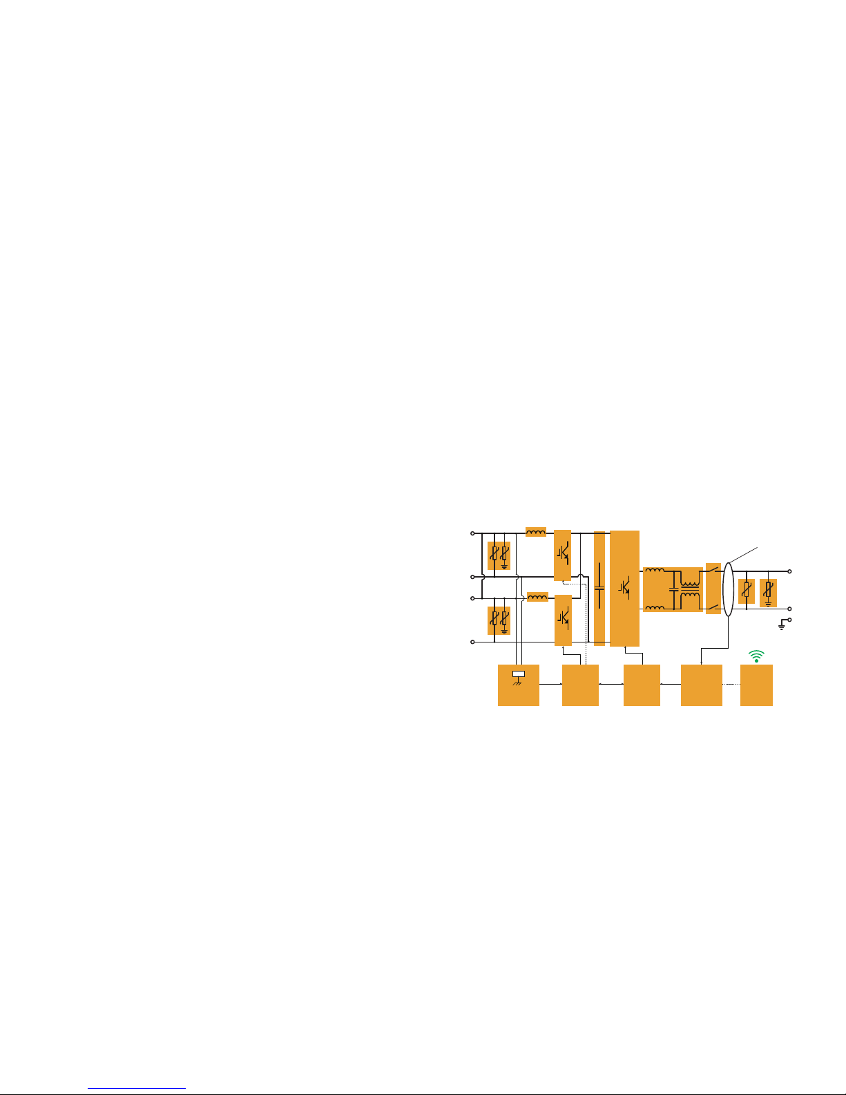
into AC current and feeds it into the public grid.
Principle of a PV plant
Figure 1 PV Grid-tied System
2.2 Important Safety Instructions
2.3 Explanation of Symbols
This section gives an explanation of all the symbols shown on the inverter and on the
type label.
2.3.1 Symbols on the Inverter
2.3.2 Symbols on the Type Label
2.3.1 Important Safety Instructions
When using the product, please do remember the below information to avoid the fire,
lightning or other personal injury:
1. Before using the Hosola inverter, read all instructions and cautionary markings on the
Hosola inverter, and all appropriate sections of this guide.
2. Use only attachments recommended or sold by Hosola. Doing otherwise may result in
a risk of fire, electric shock, or injury to persons.
Warning:
Ensure input DC voltage ≤625V. Over voltage may cause
permanent damage to inverter or other losses, which will not be included
in warranty! This chapter contains important safety and operating
instructions. Read and keep this Operation Guide for future reference.
Warning:
Authorized service personnel must disconnect both AC and DC
power from the Hosola inverter before attempting any maintenance or cleaning or
working on any circuits connected to the Hosola inverter.
Danger:
Danger to life due to high voltages in the inverter!
• All work on the inverter may be carried out by qualified personnel only.
• The appliance is not to be used by children or persons with reduced physical,
sensory or mental capabilities, or lack of experience and knowledge, unless they
have been given supervision or instruction.
• Children should be supervised to ensure that they do not play with the appliance.
Caution:
Danger of burn injuries due to hot enclosure parts!
During operation, the upper lid of the enclosure and the enclosure body may
become hot.
• Only touch the lower enclosure lid during operation.
Caution:
Possible damage to health as a result of the effects of radiation!
• Do not stay closer than 20 cm to the inverter for any length of time.
Note:
Grounding the PV generator
Comply with the local requirements for grounding the PV modules and the PV
generator. Hosola recommends connecting the generator frame and other
electrically conductive surfaces in a manner which ensures continuous conduction
and ground these in order to have optimal protection of the system and personnel.
Symbol Explanation
Danger to life due to high voltages in the inverter!
There is residual voltage in the inverter. The inverter requires 5
minutes to discharge.
Wait 5 minutes before you open the upper lid or the DC lid.
Symbol Explanation
CE mark.
The inverter complies with the requirements of the applicable
CE guidelines.
Beware of hot surface.
The inverter can become hot during operation. Avoid contact
during operation.
6 7

3. To avoid a risk of fire and electric shock, make sure that existing wiring is in good
condition and that wire is not undersized. Do not operate the Hosola inverter with
damaged or substandard wiring.
4. Do not disassemble the Hosola inverter. It contains no user-serviceable parts. See
Warranty for instructions on obtaining service. Attempting to service the Hosola inverter
yourself may result in a risk of electrical shock or fire and will void your warranty.
5. To reduce the risk of electrical shock, authorized service personnel must disconnect both
AC and DC power from the Hosola inverter before attempting any maintenance or
cleaning or working on any circuits connected to the Hosola inverter. Turning off controls
will not reduce this risk.
6. Keep away from flammable, explosive materials to avoid fire disaster.
7. The installation place should be away from humid or corrosive substance.
8. To avoid electric shock accident, please do not disassemble the inverter because inside
of inverter there are high-voltage capacitances installed. Fatal High-voltage will remain in
the inverter after its disconnection with grid after 5-10 minutes.
9. To reduce the chance of short-circuits, authorized service personnel must use insulated
tools when installing or working with this equipment.
3 Introduction
3.1 Basic Features
Congratulations on your purchase of a Hosola smart series inverter. The Hosola smart
inverter is one of the finest inverter on the market today, incorporating state-of-the-art
technology, high reliability, and convenient control features.
● Advanced MCU control technology;
● Utilize the latest high-efficiency power component from IR Company;
● Optimal MPPT technology;
● Advanced Anti-islanding solutions;
● IP65 protection level;
● Efficiency up to 97.1%;
● THD<3%;
● Safe & Reliable: transformerless design with software and hardware protection;
● Friendly HMI.
☆ LED status indications;
☆ LCD display technical data, Human-Machine interaction through press key;
☆ RS485/WIFI communication interface;
☆ PC remote control.
3.2 Electrical block diagram
3.2.1 Electrical block diagram, please see figure 2.
(4200TL /5000TL)
Figure 2
electrical block diagram
8 9
(DC/AC)
(DC/DC)
(CAP)
PV2+
PV2-
(DC/DC)
PV1+
PV1-
AC Leakage
Current
Detection
Ground Fault
Monitoring
DSP
Controller A
DSP
Controller B Wi-fi
(Line Filter)
(Grid Parallel
Relay)
L
N
PE
GFCI

Model
Weight
Hosola Bright 4200TL
18.9Kg
Hosola Bright 5000TL
18.9Kg
Table 1 Weight
4 Specifications
4 .1Specifications
(
4200TL/5000TL
)
4.2.1 DC Input
10 11
3.3.2 Terminals of PV inverter
Figure 4 Terminal of PV inverters(4200TL/5000TL)
3.3 Dimension and Weight
3.3.1 Dimension
Figure 6 4200TL/5000TL
3.3.2 Weight
Model
4300Wp 5200Wp
625Vdc
300-500
Vdc
200 - 625 Vdc
300-500
Vdc
Max.DC power for each
MPPT [W]
Max. DC Voltage
MPPT voltage range [V]
Max. DC Current [A]
Numbers of MPPT
1
2
1
2
14.5 17.5
Strings per MPPT
Turn off DC Voltage [V]
Operating Voltage
Range [V]
Hosola Bright 4200TL Hosola Bright 5000TL
4300Wp 5200Wp
Max. DC Input Power
30 Vdc

4.2.2 AC Output
4.2.3 Efficiency, Safety and Protection
4.2.4 General Specification
12 13
Model
4200W 5000W
230 / 180~270
21A
>0.99
24A
<3%(Rated power)
Single phase
On-grid Connection
Max. Output Power
Rated AC Voltage/ Range [V]
50 / 47~52
Rated AC Frequency/
Range [Hz]
Max. Output Current
0 W
THD
Power Factor
Hosola Bright 4200TL Hosola Bright 5000TL
4200W 5000W
Rated Output Power
Night Consumption
<10 W
Operation Power
Consumption
Model
Euro Efficiency
MPPT efficiency
Hosola Bright 4200TL Hosola Bright 5000TL
97.4%
99.5%
96.7%
97.4%
99.5%
96.7%
Max. Efficiency
Model
348*506*148 mm
Hosola Bright 4200TL Hosola Bright 5000TL
Dimension (W/H/D)
Wall-mounted
Installation
-20 °C ~+60 °C
Operating Temperature
Range
0% ~95%, no condensation
Relative Humidity
<2000 m
Altitude
IP 65
Protection Level
Transformerless
Isolation Type
RS232/Wifi(optional)
Communication
Interface
5 years
Standard Warranty
18.9 Kg 18.9 Kg
Weight
Convection Convection
Cooling
< 35 dBA < 35 dBA
Noise Level
AS4777,G83,G59,EN61000-3-2,EN61000-6-1/2/3/4,IEC-62109-1,
IEC-62109-2,VDE0126-1-1,EN50438
Certificates
MPPT efficiency
Yes
Overvoltage Protection
Yes
Yes
Ground Fault Protection
Yes
Grid Monitoring
Yes
Ground Fault Current
monitoring
Yes
DC Injection Monitoring
Yes
DC isolation Impedance
Monitoring

5 Function
Operation Mode
【Stand-by Mode】
The stand-by mode means that the inverter is ready to but still not connect to the grid.
Under this mode, it will continue check if PV array has enough power to feedback into
grid. When the inverter passes dump load test after startup, it will change from stand-by
mode to Checking mode.
【Checking Mode】
If inverter passed dump load test and no error/fault occurs, starts checking to deliver
power.
【On-Grid Mode】
Under this mode, inverters convert PV array’s DC into AC and feedback into grid.
CAUTION:
The inverter decreases the output power is normal in the condition of thermal protection,
but if this phenomenon often occurred, you need to check the heatsink, or considering
put the inverter in the place where have better air flow. If output power decreases
caused by electrical, please ask for professional supports.
【MPPT Mode】
The default setting is MPPT mode, the operation mode will return to MPPT after DC&AC
restart. The MPPT voltage range is 300~500V.
【Fault Mode】
If any fault/error occurred, inverter stopped delivering power until the fault/error is clear.
Some fault/error will auto recover, and some need manually restart.
【Setting Mode】
The user can get into the setting mode by press “Function” key for 6 seconds if DC is
exist. The detail information please refers to operation method in chapter 7.
6 Installation
6.1 Installation
Attention:
Checking environment where system is installed.
Check whether the installation site does not fall into none of the following conditions:
1. The ambient temperature is outside the range of tolerable ambient temperature (
-20°C to +60°C, -4°F to +140°F,).
2. Higher than the altitude of about 2,000 m above sea level.
3. Prone to damage by sea water.
4. Close to corrosive gas or liquid (for example, locations where chemicals are
processed, feed lots or poultry).
5. Exposed to direct sunlight.
6. Prone to flooding or high levels of snow pack.
7. Minimal or no air flow and high humidity.
8. Condensations.
9. Exposure to steam, vapor, or water.
10. Exposure to direct cool air.
11. Near television antenna or antenna cable.
12. Ventilation is not enough to cool the inverter, that is to say, outdoors, the inverter
requires. At least 30 cm (see table 2) of clearance between the button of the unit
and the ground, indoors, it is recommended that the same clearance between the
button of the unit and the floor be used. Installing the inverter in the place
mentioned above may cause the malfunction of the system caused by water or
high temperature inside the inverter. Please let users know that Hosola will not
compen sate the fault caused by the above situation.
14 15

Note(for Hosola Bright series):
1. The PV modules should have an IEC61730 Class A rating or equivalent. The
resistance between PV positive or negative and ground must be more than 600kohm.
2. This product can cause a dc current in the external protective earthing conductor.
Where a residual current-operated protective (RCD) or monitoring (RCM) device is
used for protection in a case of direct or indirect contact, only an RCD or RCM of Type
B is allowed on the supply side of this product.
3. The installation place should be away from humid or corrosive substance.
4. The Hosola inverters can be used outdoor.
5. Users can check the firmware version via LCD function as shown below.
6. The Isc PV is can be referred as Max. DC Current.
7. The AC output inrush current is 20A with duration time 2us.
8. The maximum output fault current of AC output is below 15mA RMS.
9. The maximum output overcurrent protection can be referred as Max. Output Current.
Table 2
Available Space Size
6.2 Preparation
Below tools are needed before installation
6.3 Installation Steps
1.Drill holes on the wall with ф 6 driller according to the size of bracket. Keep drilling
vertical to the wall, and don’t shake when drilling to avoid damage to the wall. The depth
of the holes should be about 30mm should be the same. After removing the dust in the
holes, measure the net depth of the holes. If the depth is deeper than 33mm
Warning:
A warning that when the photovoltaic array is exposed to light, it supplies a dc.
voltage to the PCE.
Warning:
The open voltage of the PV array must be less than 625V.
Over voltage may cause permanent damage to inverter
Warning:
Before installation and maintenance, AC and DC side doesn’t carry electricity, but if
DC side is just disconnected, capacitance still
contains electricity, so please wait for at least 10 minutes to ensure
capacitor completely release the energy and inverter is not electrified.
Note:
Inverter should be installed by technician.
Side
Top
Bottom
Front
Min. Size
30cm
30cm
30cm
30cm
16 17
Residual current protection:
Residual current detection and monitoring unit integrated inside,an external
residual current breaker is not required.
If an external RCD or residual current breaker is strctly required,you must use a
switch that triggers at a failure current of 100mA or higher.
Caution!
Installtion shall comply with local regulations and technical rules.
Installtion shall comply with the relevant instructions of EN62109-1/2

or less than 27mm, the expansion tubes wouldn’t be installed and tightened.
Figure 7 Installation of Expansion Pipe
2.Clean all dust outside/inside the hole and measure pitch-row before installation. It
need repositioning and drilling holes if the hole with much error. Then put expansion pipe
into the hole vertically, use rubber hammer tap pipe into the wall completely. After that,
twist 5 screws into corresponding pipes.
Figure 8 Bracket&Inverter Installation
3.Use the bracket to install the inverter onto the narrow vertical panel (or wall). Put
upper-part holes of the inverter onto the bracket. (See figure 8).
Figure 9 Fix the inverter
4.Use M4 screw to fix the bottom of the inverter. (See figure 9).
5.Complete the installation process.
18 19

6.4 Connections of the PV power system
(1)PV String Hosola Bright series inverters (4200TL/5000TL) can be connected in series
into 2-strings PV modules. Please select PV modules with excellent function and reliable
quality. Open-circuit voltage of module arrays connected in series should be <Max. DC
(Table 3) input voltage; operating voltage should be conformed to MPPT voltage range.
Table 3 DC Voltage Limitation
Please use PV cable to connect modules to inverter. From junction box to inverter,
voltage drop is about 1-2%. So we suggest the inverter install near PV module, in order
to save cable and reduce DC loss.
Note: Check polarity of module array, Max. Voltage connected in series is 625V
(DC)
Figure 10 Use multimeter to measure module array voltage
(2) AC Output
Hosola Bright series inverters (
4200TL/5000TL
) are designed for single phase grid.
Voltage range is from 180V to 260V (200V-270V for Australia), frequency is 47~51.5Hz/57
~61.5Hz. Other technical requests should comply with the requirement of local public grid.
Table 4
Cable Requirement
Breaker should be installed between inverter and grid; any load should not connect with
inverter directly.
Figure 11
Incorrect Connections between Load and Inverter
Model Hosola Bright 4200TL
4mm
2
25A
Hosola Bright 5000TL
6mm
2
32A
Cable Requirement
Breaker
20 21
Warning:
PV module voltage is very high which belongs to dangerous voltage range, please
comply with electric safety rules when connecting.
Warning:
When there is something wrong with module arrays, modules can be connected
with PV grid-tied inverter only after eliminating these problems.
Max. DC Voltage 625V(DC)

Impedance of Hosola inverter AC connecting dot should be less than 2Ω. To ensure reliable
anti-islanding function , PV cable should be used to ensure wire loss <1% than normal
power. Moreover, length between AC side and grid connecting dot should be less than
150m. Below chart is cable length, section area and wire loss:
Figure
12 AC Cable Loss
This product has AC waterproof connector parts. You have to wire AC by yourself. Please
see figure 13 and 15 for AC connector assembling guide:
Figure 13
Disassembling AC Connector parts from Inverter
Figure 14
Connected wires
Peel off about 8mm wire(L/N/E) skin.
Connected wires.
•Connected the green-yellow wire to E(Earth) in the AC Connector
•Connected the blue wire to the N(Neutral) in the AC Connector.
•Connected the brown wire to the L(Line) in the AC Connector.
Figure 15
Fixed the AC connector parts
Phillips screwdriver
22 23

Normal:
Inverter begins to operate normally with green light on. Meanwhile, feedback
energy to grid, LCD displays present output power.
Inverters will work in MPPT mode when PV voltage range is 300 ~500V, inverter will stop
feedbacks power to grid when PV power is not enough
7 Operation Method
7.1 Control Panel
Figure 17
Control Panel
Normal (green):The inverter is working in normal state;
Fault (red):The system is in fault state;
Function key:To check the operating data, detailed usage see section 7.2.
Complete AC connector parts to the inverter’s installation process. ( Figure 16)
Figure 16
6.5 Run the inverter
6.5.1 Start inverter after checking all below steps:
a. Make sure all the DC breaker and AC breaker are disconnect
b. AC cable is connected to grid correctly;
c. All PV panels are connected to inverter correctly; DC connectors which not used should
sealed by cover.
6.5.2 Start inverter:
a. Turn on DC and AC side switches;
b. Inverter will start up automatically when PV panels generate enough energy. Below is
three different states when operating, which means inverter starting up successfully.
Waiting:
Inverter is waiting to checking when output DC voltage from PV panels is greater
than 80V (lowest start-up voltage) but less than 250V(lowest operating voltage).
Checking:
Inverter will check output environment automatically when DC output voltage of
PV panels exceeds 250V and PV panels have enough energy to start inverter.
24 25
Note:
If inverter shows
“Fault”
status, please refer to Part 9
Normal (green)
Fault (red)
Function key
LCD

7.2 LCD Function
The function key is used to set the LCD. It can alternate among different parameters.
26 27
Use Function Key to
check and set inverter
Waiting
Pac=x.xW
Checking 30s
Pac=x.xW
Normal State
Pac=x.xW
HosolaBright xxxKW
Pac=x.xW
Display on LCD at first
Inverter will change into standby mode
when the dc input >80V.
when the PV voltage>250V,Inveter will
change into “Normal State” mode after
30s checking.
Normal State
Pac=xxxx.xW
Etotal=xx.xkwh
Pac=xxxx.xW
Etoday=.xxxx.xkwh
Pac=xxxx.xW
Vpv1=xx.xV
Pac=xxxx.xW
Ipv1=xx.xA
Pac=xxxx.xW
Vpv2=xx.xV
Pac=xxxx.xW
Ipv2=xx.xA
Pac=xxxx.xW
PvMode=xxxx
Pac=xxxx.xW
Initial State
LCD will light on
It display the total Energy
It display the today’s energy.
It display the PV1 voltage.
It display PV1 current.
It display PV2 voltage.
It display PV2 current.
It display PV current.
Vac=xx.xV
Pac=xxxx.xW
Iac=xx.xA
Pac=xxxx.xW
Freq.=xxxHz
Pac=xxxx.xW
HosolaBright xxxkW
Pac=xxxx.xW
Ver.V1.00
Pac=xxxx.xW
It display AC current.
It display AC voltage.
It display AC frequency.
It display inverter’s model
It display the version of
the software.
Select Language
Pac=xxxx.xW
Reset Etoday
Pac=xxxx.xW
Normal State
Pac=xxxx.xW
Language setting.
Energy today reset
It display the initial state.

28 29
Reversion informationVer xx.xxInverter’s reversion
AC Under frequency ratingFault UFR
No UtilityNo utility
PV voltage ≥625VPV over voltage
Fault Information
Other
No Utility
PV Over Voltage
Consistent Fault
Over Temperature Over temperature The inner temperature is higher
than the set value
Relay Failure Relay Failure Relay is failure between grid
and inverters
DC INJ High DC INJ High DC components over rating
in AC output
Consistent fault CPU or other circuitry failure
EEPROM Failure EEPROM Failure EEPROM’s failure
SCI Failure SCI Failure MCU internal communication
failure
High DC Bus High DC Bus
DC bus voltage is higher
than the set value
Low DC Bus Low DC Bus
DC bus voltage is lower than the
set value
2.5V Reference
Voltage Issues
Ref 2.5V Fault 2.5V reference voltage failure
DC Sensor Fault DC Sensor Fault Input DC detector failure
GFCI Failure GFCI Failure
Lock Lock Froze the information
Reconnect Reconnect Reconnect to grid after relay
disconnect
Leakage current detecting
circuit failure
7.3 LCD Information
Table 5
LCD Information
Operating State
Power Off
Initialization& Waiting
Checking
Normal State
Flash
Real-time Power Pac=xxxxW
Etotal=xxxxkwh
Vac=xxx.xV
Freq.=xx.xHz
Iac=xx.xA
Vpv= xxxV
Idc= xxx A
Real-time output power
Total energy feedback to grid
Output voltage
Output frequency
Output Current
PV input voltage
PV input current
Calculate Energy
Information
Output Frequency
Output Current
PV Input Voltage
Output Voltage
PV Input Current
Leakage Detecting
Isolation Fault Isolation fault
Ground I fault
Fault OVR AC Over voltage rating
AC Under voltage rating
AC Over frequency rating
Fault UVR
Fault OFR
Grounding fault or surge
voltage protection failure
Leakage current over rating
Fault Warning
No display DC input voltage<80V,
80V< DC Input voltage≤250V
is standby mode
Inverter is working in
grid-tied mode
Input voltage >250V is grid
checking mode
Waiting
Checking
Normal State
Flash Upgrading software
Information Display Description
Working Condition
Checking Parameters
Fault Alarm

One inverter can only be communicated with one PC at the same time through RS232
port. Thus this method is generally used for single inverter’s communication, for exam-
ples: software updating and serviceman’s testing.
9 Troubleshooting
This section contains information and procedures for solving possible problems with the
Hosola inverters, and provides you with trouble shooting tips to identify and solve most
problem that can occur with the Hosola inverters.
This section will help you narrow down the source of any problem you may encounter.
Please read the following troubleshooting steps:
1.Check for a Warning or Fault message on the System Control Panel or a Fault code
on the inverter information panel. If a message is displayed, record it before doing
anything further.
2.Attempt the solution indicated in Table 8
3. If your inverter information panel is not displaying a Fault light, check the following list
to make sure that the present state of the installation allows proper operation of the unit:
(1) Is the inverter located in a clean, dry, adequately ventilated place?
(2) Have the DC input breakers opened?
(3) Are the cables adequately sized and short enough?
(4) Are the input and output connections and wiring in good condition?
(5) Are the configurations settings correct for your particular installation?
(6) Are the display panel and the communications cable properly connected and
undamaged?
Contact Hosola Customer Service for further assistance. Please be prepared to describe
details of your system installation and provide the model and serial number of the unit.
8. Communication and Monitoring
8.1 Communication Interface
This product has an communication interface RS232. Operating information like output
voltage, current, frequency, fault information, etc., can be delivered to PC or other
monitoring equipment via RS232.
8.2 Communication
When user want to know the information of the power station and manage the entire
power system. We offer below two types communications.
RS232 Communication
RS232 is one standard communication interface. It transmits the data between PC and
one single inverter (Figure 20).
Figure 20 RS232 Communication Diagram
Figure 21 RS232 Communication Cable and Interface
30 31

Table 8
Troubleshooting list
32
Faults Diagnosis and Solutions
1 Waiting for one minute, grid will go back to normal working state
2 Making sure that grid voltage and frequency complies
with standards
3 Or, please seek for help from us
Grid Faults
1 off to grid
2 Please check grid-connection, like wire, interface, etc.
3 Checking grid usability
4 Or seek for help from us
No Utility
1 Checking the battery panel’s open-circuit voltage whether the
value is similar or already >625Vdc
2 Please seek help from us when voltage ≤625Vdc
Over PV Voltage
1 Inner temperature is higher than the set value
2 Lower the surrounding temperature by proper methods
3 Or move the equipment to a cooler location.
4 Or seek for help from us
Over Temperature
1 Output DC current is higher than the set value
2 Wait for one minute
3 Please seek for help from us if it does not go back to normal stae
Over Percentage of DC
1 Disconnect PV (+) , PV (-) with DC, and re-connect them
2 Please seek for help from us if it can not go back to normal state
String Array
Communication Fault
1 Check the impedance among PV (+)、PV (-) and ground.
Impedance should be >2Mohm
2 Please seek for help from us if it can not be detected or the
impedance is <2Mohm
Isolation Fault
33
1 Disconnect the PV (+), PV (-) with DC input, then re-connect them
2 Check L line and N line to see whether it has connection faults
3 Please seek for help from us when this fault happens
Power Pressure on the
Bus is too high
1 Disconnect the PV (+), PV (-) with DC input, then re-connect them
2 Please seek for help from us if it can not go back to normal state
Refer to 2.5V Voltage Fault
GFCI Failure
Under Voltage on the Bus
1 Disconnect the PV (+), PV (-) with DC input, then reconnect them
2 Please seek for help from us if it can not go back to normal state
Consistent Fault
1 Disconnect the PV (+), PV (-) with DC input, then reconnect them
2 Please seek for help from us if it can not go back to normal state
1 Disconnect the PV (+), PV (-) with DC input, then reconnect them
2 Please seek for help from us if it can not go back to normal state
Relay Fault
☆ Leakage current is too high
☆ Disconnect DC and AC connector, check the surrounding
equipment on the AC side
☆ Reconnect the input connector and check the state of inverter
after troubleshooting.
☆ Please seek for help from us if it can not go back to normal state
Leakage Current Fault
Invalid EEPROM
33

10 Decommissioning
10.1 Dismantling the Inverter
1. Disconnect the inverter from DC Input and AC output;
2. Remove all connection cables from the inverter.
3. Remove the inverter from the bracket.
10.2 Packaging
If possible, please pack the inverter in the original packaging.
If this is no longer available, you can also use an equivalent carton that fulfills the
following requirements:
• Suitable for loads of at least 25 kg
• With handle system
• Can be closed fully
10.3 Storage
Store the inverter in a dry place where ambient temperatures are always between -20 °C
and +60 °C.
10.4 Disposal
Please be sure to deliver waste inverters and packing materials to certain site, which
could assist relevant department to dispose and recycle.
34 35
Warranty and Return Information
Warranty
What does this warranty cover? This Limited Warranty is provided by Hosola and
covers defects in workmanship and materials in your Hosola PV inverter. This warranty
period lasts for five years from the date of purchase at the point of sale to you, the
original end user customer. You will be required to demonstrate proof of purchase to
make warranty claims.
This Limited Warranty is transferable to subsequent owners but only for the unexpired
portion of the Warranty Period. Subsequent owners also require original proof of
purchase as described in “What proof of purchase is required?”
What will Hosola do? Hosola will, at its option, repair or replace the defective product
free of charge, provided that you notify Hosola of the product defect within the Warranty
Period, and provided that Hosola through inspection establishes the existence of such a
defect and that it is covered by this Limited Warranty.
Hosola will, at its option, use new and/or reconditioned parts in performing warranty
repair and building replacement products. Hosola reserves the right to use parts or
products of original or improved design in the repair or replacement. If Hosola repairs or
replaces a product, its warranty continues for the remaining portion of the original
Warranty Period or 90 days from the date of the return shipment to the customer,
whichever is greater. All replaced products and all parts removed from repaired products
become the property of Hosola.
How do you get service? If your product requires troubleshooting or warranty service,
contact your merchant. If you are unable to contact your merchant, or the merchant is
unable to provide service, contact Hosola directly at:
Telephone: 0086 512 6281 5763
Fax: 0086 512 6281 5763-1888
E-mail: [email protected]
Direct returns may be performed according to the Hosola Return Material

Authorization Policy described in your product manual. For some products, Hosola
maintains a network of regional Authorized Service Centers. Call Hosola or check our
website to see if your product can be repaired at one of these facilities.
What proof of purchase is required?
In any warranty claim, dated proof of purchase
must accompany the product and the product must not have been disassembled or
modified without prior written authorization by Hosola. Proof of purchase may be in any one
of the following forms:
• The dated purchase receipt from the original purchase of the product at point of sale to the
end user, or
• The dated dealer invoice or purchase receipt showing original equipment manufacturer
(OEM) status, or
• The dated invoice or purchase receipt showing the product exchanged under warranty
What does this warranty not cover?
This Limited Warranty does not cover normal wear
and tear of the product or costs related to the removal, installation, or troubleshooting of the
customer's electrical systems. This warranty does not apply to and Hosola will not be
responsible for any defect in or damage to:
a) the product if it has been misused, neglected, improperly installed, physically damaged
or altered, either internally or externally, or damaged from improper use or use in an
unsuitable environment;
b) the product if it has been subjected to fire, generalized corrosion, biological infestations,
or input voltage that creates operating conditions beyond the maximum or minimum limits
listed in the Hosola product specifications including high input voltage from lightning strikes;
c) the product if repairs have been done to it other than by Hosola or its authorized service
centers;
d) the product if it is used as a component part of a product expressly warranted by another
manufacturer;
e) the product if its original identification (trade-mark, serial number) markings have been
defaced, altered, or removed.
Return Material Authorization Policy
Before returning a product directly to Hosola you must obtain a Return Material Authoriza-
tion (RMA) number and the correct factory "Ship To" address. Products must also be
shipped prepaid. Product shipments will be refused and returned at your expense if they
are unauthorized, returned without an RMA number clearly marked on the outside of the
shipping box, if they are shipped collect, or if they are shipped to the wrong location.
When you contact Hosola to obtain service, please have your instruction manual ready for
reference and be prepared to supply:
• The serial number of your product
• Information about the installation and use of the unit
• Information about the failure and/or reason for the return
• A copy of your dated proof of purchase
Return Procedure
1. Package the unit safely, preferably using the original box and packing materials. Please
ensure that your product is shipped fully insured in the original packaging or equivalent.
This warranty will not apply where the product is damaged due to improper packaging.
2. Include the following:
• The RMA number supplied by Hosola. clearly marked on the outside of the box.
• A return address where the unit can be shipped. Post office boxes are not acceptable.
• A contact telephone number where you can be reached during work hours.
• A brief description of the problem.
3. Ship the unit prepaid to the address provided by your Hosola customer service represen-
tative.
In addition to the above, you MUST include return freight funds and are fully responsible for
all documents, duties, tariffs, and deposits.
If you are returning a product to a Hosola Authorized Service Center (ASC) A Hosola return
material authorization (RMA) number is not required. However, you must contact the ASC
prior to returning the product or presenting the unit to verify any
36 37
Table of contents
Other Hosola Inverter manuals