Fujitsu Waterstage WOYG160LJL User manual

U0651595_2011_EN_2
10/09/2019
INSTALLATION
Air to Water Heat Pump Split single service
For professionals. To be kept by the user for future reference
EN
Outdoor unit
WOYG160LJL
WOYK150LJL
WOYK170LJL
Hydraulic unit
WSYG160DJ6
WSYK170DJ9

■Installation and maintenance rules
The appliance must be installed and maintained
by an approved professional in accordance with
current regulations and codes of practice.
• Warning, hydraulic unit should not be installed
in an air current.
■Handling
The outdoor unit must not be placed in a horizontal
position during transport.
If not kept upright during transport, the appliance
could be damaged through displacement of
the refrigerant and damage to the compressor
suspension.
Any damage caused by transportation in a horizontal
position is not covered by the warranty.
If necessary, the outdoor unit may be tilted only
during manual handling (to go through a door or up
a staircase). This operation must be conducted very
carefully and the appliance must be immediately
restored to the upright position.
■Containment of refrigeration circuits
All refrigeration circuits are sensitive to contamination
from dust and moisture. If such pollutants penetrate
the refrigeration circuit, they can aect the reliability
of the heat pump.
Make sure that the connections and refrigeration
circuits (hydraulic unit, outdoor unit) are
protected correctly.
In the event of a subsequent failure and following
an inspection, the presence of moisture or
foreign bodies in the compressor oil would
automatically void the warranty.
- Check upon receipt that the ttings and refrigeration
circuit caps mounted on hydraulic unit and outdoor
unit are properly seated and secured (cannot be
loosened with bare hands). If this is not the case,
tighten them using a C spanner.
- Check also that the refrigeration connections are
sealed (plastic caps or tubes crimped at the ends
and brazed). If the caps must be removed during
the installation (tubes to be re-cut for example),
put them back as soon as possible.
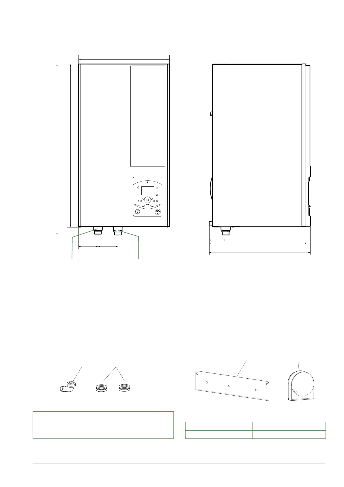
■Hydraulic connections
The connection must comply with industry standard
practice according to current regulations.
Remember: Seal everything when tting in
accordance with industry standard practice for
plumbing work:
- Use suitable seals (bre gasket, O-ring).
- Use Teon or hemp tape.
- Use sealing paste (synthetic depending on the
case).
Use glycol/water mix if the minimum ow
temperature is set below 10°C. If you are using a
glycol/water mix, arrange for an annual check on the
quality of the glycol. Use monopropylene glycol only.
The recommended concentration is 30% minimum.
Never use monoethylene glycol.
• In some installations, the presence of dierent
metals can cause corrosion problems; the
formation of metal particles and sludge can
appear in the hydraulic circuit.
• In this case, it is advisable to use a corrosion
inhibitor in the proportions indicated by the
manufacturer.
• You must also ensure that treated water does
not become corrosive.

■Electrical connections
• Before any maintenance operation, ensure
that the general power supply is switched o.
• Specications of electricity supply
The electrical installation must be carried out in
accordance with prevailing rules.
Electrical connections will only be made once all
other installation operations (fastening, assembly,
etc.) have been completed.
Warning!
The contract signed with the energy provider must
be sucient not only to cover the heat pump's power
requirements but also the combined sum of all the
appliances likely to be operating at the same time. If
the power is too low, check the power rating stated
in your contract with your energy provider.
Never use a power socket for the power supply.
The heat pump must be supplied directly with power
(without external switch) by special protected leads
from the electric panel via dedicated bipolar circuit
breakers, C curve for the outdoor unit, C curve for
the electrical heating and domestic water backups
(see tables page 35).
The electrical installation must be tted with a 30mA
RCD.
This appliance is designed to operate using a
nominal voltage of 230 V or 400 V, +/- 10%, 50 Hz
(depending on model).
• General remarks on electrical connections
It is essential to maintain neutral-phase polarity
when making electrical connections.
Rigid wires are preferable for xed installations,
particularly in a building.
Tighten the cables using the cable glands to prevent
the feed wires from being accidentally disconnected.
The earth connection and its continuity must be
ensured.
• Cable glands
To ensure the stability of power (Low Voltage) and
sensor (Extra-Low Voltage) cables, it is essential
that the cable glands are tightened according to the
following recommendations:
Size of cable
gland (PE)
(mm)
Diameter of
cable
(mm)
Cable gland
tightening
torque
(check-nut)
(N.m)
Coupling net
tightening
torque
(N.m)
PG7 1 to 5 1.3 1
PG9 1.5 to 6 3.3 2.6
PG16 5 to 12 4.3 2.6
• Connecting to screw terminals
The use of ring, spade or blade terminals or
caps is prohibited.
- Always select wire that complies with current
standards.
- Bare the end of the wire to around 25 mm.
- With round end pliers, form a loop with a diameter
which matches the tightening screws on the
terminal.
- Tighten the terminal screw rmly onto the
loop created. Insucient tightening can cause
overheating, leading to breakdown or even re.
Rigid wires Loop
25 mm Lug on
exible wires
prohibited
Screw and special
washer
Terminal
• Connecting to controller boards
- Remove the corresponding connector and make
the connection.
Pre-cabled bundle connector and/or screw connector
• Connecting to spring terminals
- Bare the end of the wire to around 12 mm.
- Push the spring with a screwdriver so that the wire
enters the cage.
- Slide the wire into the opening provided for this
purpose.
- Remove the screwdriver and then check that the
wire stays gripped by the cage by pulling on it.
2
1
3

- 4 -
Contents
Packing .................................6
Unpacking and supplies ....................6
Denitions ...............................6
Optional equipment ........................6
Operating Range ..........................6
General characteristics .....................7
Description .............................12
Operating principle .......................14
Hydraulic connections 30
Connecting the hydraulic unit to the heating circuit..30
Filling and bleeding the installation ...........31
Heating circulation pump speed settings.......32
Electrical connections 34
Cable dimensions and protection rating .......35
Electrical connections on the outdoor unit side ..36
Electrical connections on the hydraulic unit side ..38
Outside sensor ..........................42
Room sensor (optional) ....................42
Commissioning 44
Controller Interface 46
User Interface ...........................46
Display Description .......................47
Installer Menu ...........................48
Navigating the Menus .....................48
Modifying Settings ........................49
Temperature control ......................50
Description of the equipment 6
Installation 16
Installation of refrigeration connections........16 Installation of the outdoor unit ...............18
Installation of the hydraulic unit ..............20
Refrigeration connections 22
Rules and precautions.....................22
Shaping the refrigeration pipes ..............22
Checks and connection ....................25
Filling the installation with gas...............26
Waterstage / Installation / 2011 - EN
This appliance must be installed by qualied personnel holding a certicate of competence in the
handling of refrigerants.

- 5 -
Controller Menu 52
Basic Hydraulic Layout 70
Electrical Cabling Plans 72
Fault Diagnosis 76
Faults in the Hydraulic Unit .................76 Faults in the Outdoor Unit ..................77
Maintenance of the installation 78
Hydraulic checks .........................78
Checking the outdoor unit ..................78
Electrical checks .........................78
Other maintenance 79
Emptying the hydraulic unit .................79 Distribution valve .........................79
Quick-start procedure 80
Menu Structure ..........................52
Installed options .........................53
Hydraulic conguration ....................53
Heat Pump Conguration ..................58
System status ...........................60
Auxiliary functions ........................62
Settings ................................64
Easy Start ..............................68
Start-up check-list ........................80 Commissioning technical datasheet ..........82
Instructions for the end user 83
Waterstage / Installation / 2011 - EN
Other manuals for Waterstage WOYG160LJL
1
This manual suits for next models
4
Table of contents
Other Fujitsu Inverter manuals
Popular Inverter manuals by other brands

BARRON
BARRON EXITRONIX Tucson Micro Series installation instructions

Baumer
Baumer HUBNER TDP 0,2 Series Mounting and operating instructions

electroil
electroil ITTPD11W-RS-BC Operation and Maintenance Handbook

Silicon Solar
Silicon Solar TPS555-1230 instruction manual

Mission Critical
Mission Critical Xantrex Freedom SW-RVC owner's guide

HP
HP 3312A Operating and service manual