manuals.online logo
Brands
  1. Home
  2. •
  3. Brands
  4. •
  5. Hotline
  6. •
  7. Power Supply
  8. •
  9. Hotline HLS200 User manual

Hotline HLS200 User manual

1
55
11 12
910
6
7
8
2
3
1. Fold out solar panel array
2. Switch with pulse/low battery indicator
3. Ground connection terminal
4. Fence connection terminal
5. Battery access twist knobs
6. Mounting slot
7. Battery box
8. Battery charge socket
9. Ground connection lead
10. Fence connection lead
11. Battery charger
12. Wall/post mounting bracket
Key
Getting to know your energiser.
Please read through before installation. Please read safety guidelines leaet.
Installation guide - Type: HLS200
4
Connecting it all together
HLS energisers include internal 12v batteries and are ready to operate out of the packaging
although we do recommend charging the energiser for 12 hours prior to use. Please see
section on charging the battery.
Unscrew the terminals and slide on the ring terminals on the earth and fence leads.
Securely tighten.
Fold out the two side panels fully
prior to use.
Lead connection
Panels
Fence connection
Connect the lead with the red croc
clip to the fence (from red terminal)
& the green croc clip (from the green
terminal) to the ground rod. We
recommend a minimum of one ground
rod driven approx. one metre into
the ground. If possible, position the
energiser with the panel facing south
and with a clear line of sight avoiding
obstructions such as tree cover.
910
10
9
Mounting
Battery access
Switching on and off Charging the battery
Energisers can be mounted on
the wall/post bracket provided or
alternatively on 47ES3 and 47EST1
earth stakes (purchased separately).
If sitting on the ground, ensure the
panel is not obstructed by vegetation.
Connection to the fence
From time to time the bat-
tery may need recharging.
It is especially important to
keep the battery charged
when the energiser is not
in use and stored away
from direct sunlight. Insert
the male jack plug on the
charger into the socket on
the side of the energiser,
and plug the head into the
wall socket.
The charger must not
be used to operate the
energiser from mains
supply.
Press the switch on the front of the
energiser. There will be a short delay before
the switch will begin to ash green in time
with the pulse. The switch will ash blue
when battery power is getting low and red
when charging is needed.
If access to the battery is required for
replacement or checking, rotate the red
twist knobs outwards 90 degrees and hinge
the panel section forward. The battery can
be removed by unscrewing the battery
retaining strap.
Trouble shooting
You should have a minimum of 3kv on your fence line to be e󰀨ective. In principle, electric
fencing is a simple concept. If your energiser is working then there can only be two other
places to look - your fence line or ground system.
Sound and sight - Most energisers emit an audible tick caused by the ring of the output
transformer. This is a good indication that the energiser working. The indicator light or fence
monitor should be pulsing or ashing. The energiser has a pulse indicator, and this should
be operating at all times. If the light is ashing green it usually means that the energiser is
working correctly. This indicates that the problem is somewhere on the fence system. If red
then your battery needs charging*. Flash test - disconnect the croc clips from the fence
and ground stake. Clip the croc clips together making sure the metal jaws contact each
other. Slowly draw them apart - you should get a short (1-2mm)spark jumping from one to
the other. Use a Tester - disconnect completely from the ground stake and fence and take
a reading across the terminals. Depending on the model of energiser you should have a
reading between 7 and 10kv.
Low voltage - If there is high voltage on your ground stake it is missing from your fence line.
The greater the depth and surface area under the ground the more e󰀩ciently your ground
stake will collect the pulse as it returns through the earth. If you get a shock from your ground
stake, or your tester shows voltage when touched to the ground stake, you can improve
your whole system by adding further ground stakes. Link additional ground stakes with wire,
spacing them about a metre apart.
Clear lines - An electric fence operates as an open circuit. The fence is positive and the
ground itself is negative. By touching both fence and ground the animal completes the circuit
and get the shock. If anything touches both ground and fence, other than the animal, it
reduces the e󰀨ective voltage on the fence line. The fence line must not touch anything that is
not insulated from the ground. Check the fence line is clear from all vegetation and wooden
posts, metal posts and gates are not touching the line. Check all insulators. The fence line
can occasionally come unhooked from insulators and touch the posts and broken insulators
can cause leaking of power into the post and ground. Line problems - If you are joining
two sections of tape or wire, try to use correct connectors to ensure the conductors in both
sections are connected. Check the condition of the line, if the metal conductors within the
line are broken it will e󰀨ect the e󰀩ciency of the fence. Greater metal content means greater
e󰀩ciency. Netting - Netting is closer to the ground than other forms of fence so requires
more maintenance to keep clear from vegetation. All horizontal lines, apart from the bottom,
must be kept clear from the ground. If your net is sagging and touching the ground, add
in extra posts. The net must also be clear of contact from other forms of fencing, arks and
chicken wire runs. Check the metal spikes on the posts, occasionally wires can get caught
up or slip down to the metal spike and take power to ground. Remember- if your energiser
and ground system is ne, the problem will be somewhere on your fence line!
If in doubt, Call - We are always happy to help. +44(0)1626 33 11 88
Checking the energiser
Checking the ground system
Checking the fence line

This manual suits for next models

1

Other Hotline Power Supply manuals

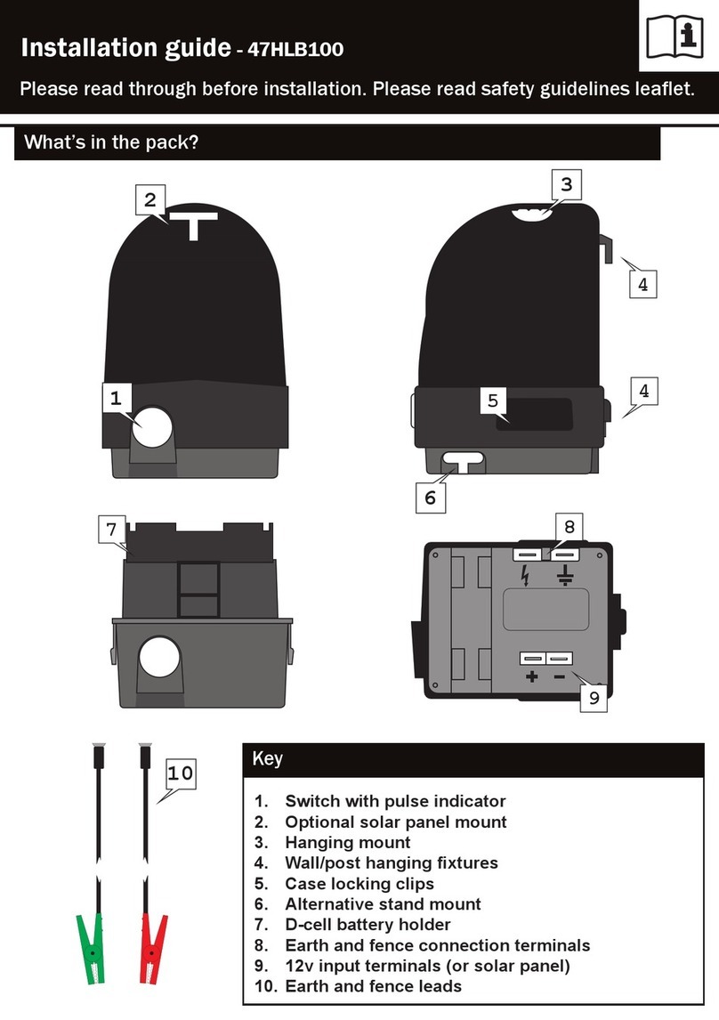
Hotline 47HLB100 User manual

Hotline

Hotline 47HLB100 User manual

Hotline 85892F User manual

Hotline

Hotline 85892F User manual

Popular Power Supply manuals by other brands

Riello STEEL PRO POWER INSTALLATION, TECHNICAL ASSISTANCE SERVICE AND SYSTEM MANAGEMENT MANUAL

Riello

Riello STEEL PRO POWER INSTALLATION, TECHNICAL ASSISTANCE SERVICE AND SYSTEM MANAGEMENT MANUAL

Emerson Universal-R Installing and operating instructions

Emerson

Emerson Universal-R Installing and operating instructions

Pulsar HPSB 11A12E manual

Pulsar

Pulsar HPSB 11A12E manual

RCS EP-352 manual

RCS

RCS EP-352 manual

CAMBRIONIX PD-Sync4 user manual

CAMBRIONIX

CAMBRIONIX PD-Sync4 user manual

TEXIO PDS20-10A instruction manual

TEXIO

TEXIO PDS20-10A instruction manual

Rocket Fish RF-700WPS2 user guide

Rocket Fish

Rocket Fish RF-700WPS2 user guide

Automationdirect.com Productivity 2000 P2-01DCAC manual

Automationdirect.com

Automationdirect.com Productivity 2000 P2-01DCAC manual

InkMachines RPS-600 manual

InkMachines

InkMachines RPS-600 manual

HP UPS user guide

HP

HP UPS user guide

Monacor PSS-1500SV quick guide

Monacor

Monacor PSS-1500SV quick guide

Rigol DP800A Series quick guide

Rigol

Rigol DP800A Series quick guide

Meridian Prime user guide

Meridian

Meridian Prime user guide

Bticino E56 manual

Bticino

Bticino E56 manual

RPC 50P00P user manual

RPC

RPC 50P00P user manual

Branson DCX A Series Original instructions

Branson

Branson DCX A Series Original instructions

BEHLMAN P1350 User's guide and technical reference manual

BEHLMAN

BEHLMAN P1350 User's guide and technical reference manual

Matsusada Precision CO Series instruction manual

Matsusada Precision

Matsusada Precision CO Series instruction manual

manuals.online logo
manuals.online logoBrands
  • About & Mission
  • Contact us
  • Privacy Policy
  • Terms and Conditions

Copyright 2025 Manuals.Online. All Rights Reserved.