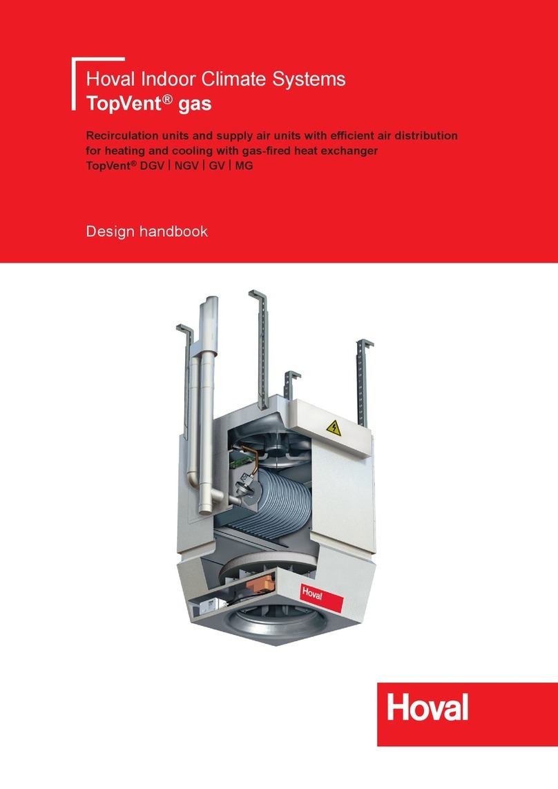
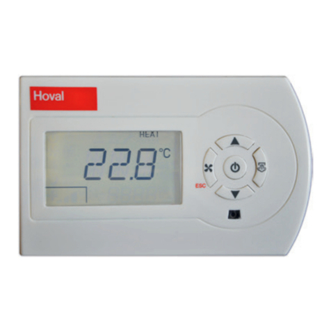
Hoval TempTronic MTC User manual

TempTronic MTC
Operating Instructions
TempTronic MTC
Room temperature controller
for TopVent®GV units
4 220 655-en-00

1 Use 3
1.1 Intended use .................................................................. 3
1.2 User group..................................................................... 3
2 Basic principles 4
2.1 Operating elements........................................................ 4
2.2 Language....................................................................... 5
2.3 Time and date ................................................................ 5
2.4 Display........................................................................... 5
2.5 Keyboard locking ........................................................... 6
2.6 Reset ............................................................................. 6
3 Programming 7
3.1 Temperature setpoints.................................................... 7
3.2 Clock program................................................................ 7
3.3 Heating program ............................................................ 8
3.4 Destratication ............................................................... 8
3.5 Optimisation................................................................... 9
4 Manual operation 9
4.1 Overtime program .......................................................... 9
4.2 Summer ventilation ........................................................ 9
5 Calibration 10
6 External sensor 10
7 External switching 11
8 Alarms 12
9 Information menu 13
10 Installer menu 14
11 Internal battery 15
2
TempTronic MTC
4 220 655-en-00 4 220 655-en-00
Content

1 Use
1.1 Intended use
The TempTronic MTC is a programmable room temperature controller for up to
8 TopVent® GV units. It fulls the following functions:
■Regulation of the room temperature with setting option for 3 temperature
setpoints (0…30 °C)
■Clock programme with 10 programmable time blocks
■Summer ventilation (in 3 speeds)
■Destratication mode
■Recording the room temperature with the integrated temperature sensor
■Connection option for external temperature sensor (instead of the integrated
sensor or for averaging)
■Alarm display and reset
■External switching (o/clock program)
■Keypad lock
■Password protection
Communication is via a 2-wire low-voltage bus system. The TempTronic MTC
cannot be used for 24 V, 230 V or other signals. It may only be used in dry,
dust-free rooms (protection rating IP 30).
Intended use also includes compliance with the operating instructions. Any usage
over and above this use is considered to be not as intended. The manufacturer
can accept no liability for damage resulting from improper use.
1.2 User group
There are 2 user levels:
User level User group Access rights Access
User Trained users ■Setting of temperature
setpoints
■Setting of operating
modes
■Programming
■Alarm processing
free
Installer Experts In addition:
■Setting of control
parameters
Protected by a password
Factory setting
password:
0543
2 3
TempTronic MTC Use
4 220 655-en-00

2 Basic principles
2.1 Operating elements
The device is operated via a 4-line display and 4 keys:
14:08
20°C
Fig. 1: TempTronic MTC
Key Function
■View information
■Access and exit menu
■Conrm values and settings
■Increase values
■Navigation upwards
■Decrease values
■Navigation downwards
Table 1: Key assignment
4
TempTronic MTC Basic principles
4 220 655-en-00 4 220 655-en-00

2.2 Language
Menu → Settings → Language
Language
Nederlands
→Deutsch
English
Select the desired language:
■Nederlands
■Deutsch
■English
■Francais
■Italiano
■Polski
■Lietuviu
■Cesky
■Dansk
■Russkij
Operating example – How to navigate through the menu:
■To access the menu, press .
■Select the menu item 'Settings' with and press .
■Select the menu item 'Language' with and press .
■Select the desired language with and press .
■To exit the menu, press 2 × .
2.3 Time and date
Menu → Settings → Time/Date
Time/Date
DST On
Time 14:07
Date 24-03-2021 We
■Activate or deactivate automatic changeover
between summer and winter time (Daylight
Saving Time 'DST').
■Set the time and date.
2.4 Display
Menu → Settings → Display
During operation, the time, the room temperature, the valid temperature setpoint
(optional) and, if applicable, alarms are displayed. You can choose between
3 variants for the arrangement on the display:
14:08 Disp1
20°C
■Select the desired display variant:
20°C Disp2
14:08
14:08 Disp3
20°C
Setpoint 21°C
4 5
TempTronic MTC
Basic principles Basic principles
4 220 655-en-00

2.5 Keyboard locking
Keyboard locking is used to protect the controller against unauthorised changing
of the settings. The following security levels can be selected:
■On (keyboard locked)
■O (keyboard unlocked)
■On excl. overtime (access to the overtime program only, see section 4.1)
Menu → Keyboard locking
Keyboard locking
→Keylock code
On
Off
■To modify the unlocking code, select
'Keylock code' and press .
Keylock code
0.0.0.0
■Enter the desired unlocking code.
Keyboard locking
→On
Off
On excl. overtime
■Select the security level.
Unlocking the keyboard
■Press and hold the key for 10 seconds.
■Enter the unlocking code.
Notice
The factory setting for the unlocking code is: 0000
2.6 Reset
You can reset the controller to the factory settings with a reset:
Reset Heater
■Press and hold the key for 10 seconds.
■Conrm with .
■All settings are deleted.
6
TempTronic MTC Basic principles
4 220 655-en-00 4 220 655-en-00

3 Programming
3.1 Temperature setpoints
In automatic mode, the controller works with 3 dierent setpoints for the room
temperature, each of which can be set from 0...30 °C: 'Day', 'Night' and 'Frost'. The
period for their validity can be freely dened in the clock program.
Menu → Settings → Temperatures
Temperatures
Day 21 °C
Night 15 °C
Frost 6 °C
■Set the desired setpoints for automatic
operation according to the clock program.
3.2 Clock program
The clock program is used to dene regular weekly switching times. You can
program up to 10 time blocks. A block looks like this, for example:
Program Block 1
Mo Tu We Th Fr
07:00 Day
17:00 Night
■Days on which the block is valid
■Switching time 1 and temperature setpoint
■Switching time 2 and temperature setpoint
The following options are available for the days of validity:
■Off
■Mo Tu We Th Fr Sa Su
■Mo Tu We Th Fr
■ Sa Su
■Mo
■Tu
(... and so on until Sunday)
Menu → Settings → Clock program
Program Block 1
Off
■Scroll through the programmed blocks
with .
■To edit the selected block, press .
Program Block 1
Mo Tu We Th Fr
07:00 Day
17:00 Night
■Select the validity days with and
press .
■Set '07', '00', 'Day' with and conrm
each time with .
■Set '17', '00', 'Night' with and conrm
each time with .
■Go on to the next block: Press .
■Delete block: Select 'Off' and press .
■To exit the menu, press 2 × .
6 7
TempTronic MTC
Basic principles Programming
4 220 655-en-00

3.3 Heating program
In the heating program, you can choose between automatic operation according to
the clock program or continuous operation with a specic temperature setpoint:
■Clock program:
– The controller switches the setpoints as dened in the clock program.
– You can change the temperature manually. The manually changed value
remains valid until the next automatic switching time.
■Continuous day:
– The controller operates continuously with the 'Day' setpoint.
– You can change the temperature manually.
■Continuous night:
– The controller operates continuously with the 'Night' setpoint.
– You can change the temperature manually.
■Continuous frost:
– The controller operates continuously with the 'Frost' setpoint.
– You can change the temperature manually.
Menu → Settings → Heating prog.
Heating prog.
Clock program
→Cont. Day
Cont. Night
■Select the desired heating program.
3.4 Destratification
Destratication mode is used to avoid heat accumulation under the hall ceiling.
When this function is activated, the controller continuously compares the air
temperatures in the ceiling area and in the occupied area. If the temperature
dierence becomes too great (factory setting 12 K), it switches on the fans of the
connected units and switches o the heating until a balanced temperature level is
reached again.
Menu → Settings → DeltaT active
DeltaT active
→On
Off
■Activate the destratication mode, if requested.
8
TempTronic MTC Programming
4 220 655-en-00 4 220 655-en-00

3.5 Optimisation
You can set the controller so that it starts heating up in automatic mode before the
entered switching time. Heat-up is optimised so that the desired temperature is
reached at the actual switching time.
Notice
■After activating this function, it will take a few days for the controller to
gather the information needed for optimisation.
■The function is programmed so that individual colder or warmer nights
are not immediately included in the calculations.
■Heat-up starts at the earliest 3 hours before the programmed switching
time and not before midnight.
Menu → Settings → Optimiser
Optimiser
→On
Off
■Activate optimisation, if requested.
4 Manual operation
4.1 Overtime program
Use the overtime program if the controller is working in automatic mode and
the current temperature setpoint is to be maintained for a longer period of time
(beyond the programmed switching time).
The overtime timer can be set in 15-minute increments.
Menu → Overtime program
Overtime program
01:15
■Enter the time period. The countdown starts
immediately when you press the key.
4.2 Summer ventilation
The fan can be switched manually to 3 speeds without the heating being in
operation. This can have a cooling eect in summer.
Menu → Ventilation
Ventilation
Off 1 →2 3
■Select the desired speed.
8 9
TempTronic MTC
Programming Manual operation
4 220 655-en-00

5 Calibration
The measured value of the integrated temperature sensor may deviate from the
actual temperature under unfavourable circumstances (e.g. due to sunlight or
installation on an outside wall). You can compensate for this temperature dier-
ence using the calibration function.
Menu → Settings → Calibration
Calibration
Temp. difference
-2.0
■Enter the correction value.
Example:
– The displayed value is 2 °C too high.
– Enter: -2.0
6 External sensor
Optionally, an external room temperature sensor can be connected to the
controller (for connection, see wiring diagram). You can use the measured value of
the external sensor either instead of the integrated sensor or for averaging.
Possible faults of the external sensor are shown on the display (error 3 = no
sensor found).
Menu → Installer → Password → Remote sensor
Remote sensor
→Used
Not used
Average
■If requested, activate the external sensor and
select the desired use.
Notice
The factory setting for the password is: 0543
10
TempTronic MTC Calibration
4 220 655-en-00 4 220 655-en-00

7 External switching
Optionally, an external signal can be connected to the controller (for connection,
see wiring diagram). This way, the units can be controlled via a door contact or
an external time switch, for example. Dene the desired operating principle in the
installer menu:
■Contact closed = O
– The controller works according to the active heating program.
– When the contact is closed, the units are switched o, regardless of the
current heat demand.
■Contact closed = Burn
– The controller works according to the active heating program.
– When the contact is closed, the units are switched on, regardless of the
current heat demand.
■Remote clock:
– The external signal switches between the setpoint day (contact closed) and
setpoint night (contact open) set in the controller.
Menu → Installer → Password → External contact
External contact
→Closed = OFF
Closed = Burn
Remote clock
■Select the desired operating principle.
Notice
The factory setting for the password is: 0543
10 11
TempTronic MTC
Calibration External switching
4 220 655-en-00

8 Alarms
The system monitors itself. All alarms are entered in the alarm list and displayed
on the screen.
Communication error
If the controller cannot communicate with the connected units, a communication
error is displayed.
Check heater address ■Check the unit addressing (setting of the micro
switches on the burner control).
Burner malfunctions
If an error has occurred in one or more of the connected units, an alarm is
displayed.
15:45
Heater Error
20 °C
■To view more details, press .
■Switch between several connected units with
.
Heater 1
Error A1 (1)
IGNIT ERROR
→Reset heater
■If a reset is possible for the error in question,
this is indicated accordingly: Press .
Caution
Do not carry out a reset again and again if faults occur frequently with a
unit. Have the system checked by Hoval customer service.
12
TempTronic MTC Alarms
4 220 655-en-00 4 220 655-en-00

9 Information menu
The information menu displays additional information about the connected units.
■Press and hold the key for 5 seconds, to access the information menu.
■Switch between several connected units with .
■Press again, to view more information about the selected unit.
■Press the key, to scroll through the pages.
■To exit the menu, press 2 × .
■If no unit is found, the display shows 'Heater 1 N.C.'.
Heater 1 HA NG 50kW Info page 1
Description of the unit
Heater 1 HA NG 50kW
STANDBY_0
Tcy Ttop 23,0
Tx1 22,0 Tx2 22,0
Info page 2
Line 1: description of the unit
Line 2: current status
Line 3 +4: measured values of the temperature sensors
Tcy ...........not used
Ttop .........stratication sensor
Tx1 / Tx2...temperature sensor on the heat exchanger
Heater 1 HA NG 50kW
STANDBY_0
Ion 0 Ac 0 Sf 0
Mi4350 Ig4600 Ma6000
Info page 3
Line 1: Description of the unit
Line 2: current status
Line 3 +4:
Ion............ionisation level 0-90
Ac ............current speed of the gas blower
Sf .............current modulation level of the fan 0-255
Mi.............minimum speed of the gas blower
Ig..............ignition speed of the gas blower
Ma............maximum speed of the gas blower
Heater 1 HA NG 50KW
BURN_0
Appl.act.days : 15
Burn.act.hours : 25
Info page 4
Line 1: Description of the unit
Line 2: current status
Line 3: Number of days the unit is supplied with power
Line 4: Number of burning hours
Heater 1 HA NG 50KW
Ignit. ok : 20
Ignit.failed : 2
Flame failures: 1
Info page 5
Line 1: Description of the unit
Line 2: Number of successful ignitions
Line 3: Number of failed ignitions
Line 4: Number of ame failures
Heater 1 33 33 42 80
CRC:2B69 42 -- -- --
Blocking -- -- -- --
History: -- -- -- --
Info page 6
■Shows the last 16 E errors (temporary burner malfunctions).
■The ashing number is the last error.
■The CRC code is the software version of the unit.
Heater 1 1 1 -- --
CRC:2B69 -- -- -- --
Blocking -- -- -- --
History: -- -- -- --
Info page 7
■Shows the last 16 L errors (locking burner malfunctions).
■The ashing number is the last error.
■The CRC code is the software version of the unit.
12 13
TempTronic MTC
Alarms Information menu
4 220 655-en-00

10 Installer menu
Menu → Installer → Password
Notice
The factory setting for the password is: 0543
The following parameters can be set in the installer menu:
■Heater modes (modulation of the heater)
– Full modulation .............. full modulation of the heater (standard)
– Heater high.................... only high power level
– Heater mid..................... only middle power level
– Heater low ..................... only low power level
– Heater low & mid ........... only low and middle power level
– Heater mid & high.......... only middle and high power level
■DeltaT hysteresis
– Hyst up .......................... 12°C (switching on destratication mode)
– Hyst down...................... 8°C (switching o destratication mode)
■DeltaT2 hysteresis (not used)
■Hysteresis (has an inuence on the temperature control)
– 0.3 °C
■I Factor (has an inuence on the temperature control)
– I 5 min.
– Only change this value after consulting Hoval customer service.
■DeltaT2 control (not used)
■Remote sensor
– see section 6
■View mode only
– Yes/No
In view mode, the temperature control is deactivated. Only the key can be
used to display information about the units.
To exit view mode:
– Press and hold the key for 10 seconds.
– Call up the installer menu to change the setting.
■External contact
– see section 7
14
TempTronic MTC Installer menu
4 220 655-en-00 4 220 655-en-00

11 Internal battery
The internal battery ensures that the controller's clock continues to run even in the
event of a power failure. To replace the battery:
■Using a at screwdriver, press into the opening at the bottom of the controller
and carefully detach the front part of the controller from the wall plate.
■Carefully prise the print plate out of the holder.
■Replace the battery.
■Reassemble the controller.
■Dispose of the battery in accordance with local regulations.
Fig. 2: Opening TempTronic MTC
14 15
TempTronic MTC
Installer menu Internal battery
4 220 655-en-00

Contact
International
Hoval Aktiengesellschaft
9490 Vaduz
Liechtenstein
Tel. +423 399 24 00
www.hoval.com
United Kingdom
Hoval Ltd.
Northgate, Newark
Notts
NG24 1JN
Tel. 01636 672711
www.hoval.co.uk
16
TempTronic MTC
4 220 655-en-00
Contact
Table of contents
Other Hoval Temperature Controllers manuals