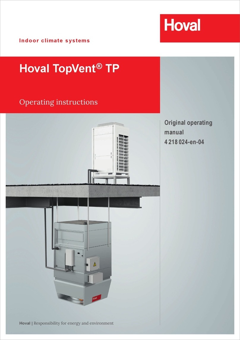
Hoval TopVent DGV Series Guide

Hoval Indoor Climate Systems
TopVent ®gas
Recirculation units and supply air units with ecient air distribution
for heating and cooling with gas-red heat exchanger
TopVent®DGV |NGV |GV |MG
Design handbook


A
B
C
D
E
F
G
H
I
Safety 3
TopVent®DGV
Gas-fired recirculation unit for heating high spaces
5
TopVent®NGV
Gas-red air recirculation unit for heating high spaces
with lower comfort requirements (e.g. high rack storage areas)
19
TopVent®GV
Gas-red air recirculation unit for heating low-ceiling spaces
33
TopVent®MG
Gas-red supply air handling unit for ventilating and heating high spaces
47
Options 61
Control system
TempTronic RC
67
System design 71
Operation 75
1
TopVent ®gas Content

2

Safety A
1 Symbols...............................................................................................4
2 Operational safety................................................................................4
3 Information for a user manual ..............................................................4
3
Safety Content

1 Symbols
Caution
This symbol warns against risk of injury. Please heed
all instructions designated by this symbol to prevent
injuries and/or death.
Attention
This symbol warns against property damage. Please
heed the respective instructions to prevent risk of
damage to the unit and its functions.
Notice
This symbol denotes information about the economic
use of the equipment or special tips.
2 Operational safety
TopVent® gas units are state-of-the-art and safe to operate.
Nevertheless, hazards may emanate from the units if they
are used incorrectly or not used as intended. Therefore:
■Please read the operating instructions before unpacking,
installing, commissioning and before maintaining the
equipment.
■Store the operating instructions so that they are easily
accessible.
■Observe any attached information and warning signs.
■Unauthorised reconguration or modication of the unit is
not permitted.
■Follow the local safety and accident prevention regula-
tions at all times.
■TopVent® gas units may only be installed, operated and
maintained by authorized, trained and instructed skilled
personnel. Specialists as dened by these operating
instructions are those persons who, based on their
training, knowledge and experience as well as their knowl-
edge of the relevant regulations and guidelines, can carry
out the work assigned to them and recognise potential
hazards.
3 Information for a user manual
According to the accident prevention regulations of some
countries, the operator of equipment must meet certain
requirements for the prevention of occupational accidents
and instruct the operating personnel as to the hazards that
may occur and how to prevent them. This can be done with
the help of the user manual.
In addition to national regulations for accident prevention and
environmental protection, a user manual should also include
the most important items of the operating instructions.
4
Safety Symbols

TopVent®DGV
Gas-fired recirculation unit for heating high spaces
B
1 Use ......................................................................................................6
2 Construction and operation..................................................................6
3 Technical data......................................................................................9
4 Dimensions and weights ....................................................................12
5 Design example .................................................................................13
6 Options ..............................................................................................14
7 Control system...................................................................................14
8 Transport and installation...................................................................14
9 Specication texts..............................................................................17
5
TopVent ®DGV Content

1 Use
1.1 Intended use
TopVent® DGV units are heaters intended for heating high
spaces operating with air recirculation.
Intended use also includes compliance with the operating
instructions. Any use beyond this is considered improper
use. The manufacturer can accept no liability for damage
resulting from improper use.
1.2 User group
The units are only allowed to be installed, operated and
maintained by authorised and instructed personnel who
are well acquainted with the units and are informed about
possible dangers.
The operating instructions are for operating engineers and
technicians as well as specialists in building, heating and
ventilation technology.
1.3 Hazards
TopVent® DGV units are state-of-the-art and safe to operate.
Despite every precaution being taken, potential and not
immediately obvious risks always remain, for example:
■Dangers when working with the electrical system
■Dangers when working with components of the gas circuit
■When working on the unit, objects (e.g. tools) could be
dropped.
■Malfunctions as a result of defective parts
■Danger caused by coming in contact with hot components
when carrying out work inside the unit or on the ue gas
system
2 Construction and operation
TopVent® DGV has been specially developed for use in high
spaces. It fulls the following functions:
■Heating (with gas-red heat exchanger)
■Recirculation operation
■Air distribution with Air-Injector
■Air ltration (optional)
The unit is mounted under the ceiling and draws in interior
air. The air is heated in a gas-red heat exchanger and
injected back into the room through the Air-Injector.
Thanks to its high performance and ecient air distribution
the TopVent® DGV covers a large area. Therefore, compared
to other systems, fewer units are needed to achieve the
required conditions.
2 dierent unit sizes and diverse output levels, as well as a
broad range of accessories make possible solutions tailored
to the requirements of each individual hall.
2.1 Unit construction
TopVent® DGV consists of the heater unit and the air injector.
Both components are bolted together, but can be dismantled
separately again.
2.2 Air distribution with the Air-Injector
The patented air distributor – called the Air-Injector – is the
core element. The air discharge angle is set by means of the
adjustable guide vanes. It depends on the air ow rate, the
mounting height and the temperature dierence between
the supply air and room air. The air is therefore blown into
the room vertically downward, conically or horizontally. This
ensures that:
■with each unit a large area of the hall can be covered,
■the occupied area is draught-free,
■the temperature stratication in the room is reduced, thus
saving energy.
6
TopVent ®DGV Use

1
2
3
4
5
6
7
8
9
10
■
1
Flue gas connection
■
2
Combustion air connection
■
3
Gas connection
■
4
Terminal box with isolation switch
■
5
Fan
■
6
Casing
■
7
Gas control valve
■
8
Burner unit consisting of stainless steel
gas blower and premix burner
■
9
Heat exchanger of stainless steel
■
10
Air-Injector
Fig. B1: TopVent®DGV structure
■
1
Heating section
■
2
Air-Injector
Fig. B2: TopVent®DGV components
B
7
TopVent ®DGV Construction and operationUse

2.3 Operating modes
TopVent® DGV operates in the following modes:
■O
■Recirculation
■Recirculation night
■Recirculation speed 1
TempTronic regulates these modes of operation automatically.
Code Operating mode Description
OFF Off
The fan is switched off. Frost protection for the room remains active.
There is no room temperature control.
Fan ..............................off
Heating ........................off
REC Recirculation
On/off-operation: if heating is required, the unit draws in room air, heats it and
returns the warm air back into the room. The room temperature set value day
is active.
Fan ..............................speed 1 / 2 1)
Heater..........................60…100 %
1) Depending on heat demand
RECN Recirculation night
like REC, but with room temperature set value night
REC1 Recirculation speed 1
The same as REC, but the unit operates only at speed 1
(low air flow rate)
Fan ..............................speed 1 1)
Heater..........................60…100 %
1) Depending on heat demand
Table B1: TopVent®DGV operating modes
8
TopVent ®DGV Construction and operation

3 Technical data
3.1 Type code
DGV - 6 / 30 /...
Unit type
TopVent®DGV
Unit size
6 or 9
Output in kW
30 or 60
Options
Table B2: TopVent®DGV type code
3.2 Application limits
Ambient temperature min. °C - 15
max. °C 35
Supply air temperature max. °C 60
The units cannot be used in:
■Damp locations
■Places with a corrosive or aggressive environment
■Spaces with a large amount of dust
■Areas where there is danger of explosion
Table B3: TopVent®DGV application limits
3.3 Air flow rate, gas consumption
Unit type DGV-6/30 DGV-6/60 DGV-9/60
Fan speed 121212
Fan speed min-1 720 900 910 1280 670 900
Nominal air flow rate 1) m³/h 4100 5700 5100 7000 6400 8200
Floor area reached 2) m² 337 502 437 661 585 826
Nominal heat input max. kW 32.0 66.0 66.0
Nominal heat output max. kW 29.2 60.5 60.5
Combustion efficiency 3) %min. 91 min. 91 min. 91
Emissions of nitrogen oxides (GCV) mg/kWh 35.0 42.0 42.0
Emission efficiency %95.4 92.7 94.1
Seasonal space heating energy efficiency %76.1 74.4 75.6
Gas consumption
Natural gas: G20, G27 (H, E, Lw) m³/h 3.4 7.0 7.0
Natural gas: G25, G25.3 (L, LL, K) m³/h 3.8 7.9 7.9
1) At an air temperature of 20 °C
2) Mounting height Hmax = 11 m for a temperature difference between supply air and room air of up to 30 K
3) In accordance with EN 1020
Table B4: TopVent®DGV technical data
B
9
TopVent ®DGV Technical dataConstruction and operation

3.4 Electrical connection
Unit type DGV-6/30 DGV-6/60 DGV-9/60
Supply voltage V AC 400 3N 400 3N 400 3N
Permitted voltage tolerance %+10 / -15 +10 / -15 +10 / -15
Frequency Hz 50 50 50
Power consumption
at rated heating capacity W694 1124 1014
at minimal capacity W514 654 714
in standby mode W 5 5 5
Current consumption max. A1.7 2.7 2.2
Protection rating –IP 20 IP 20 IP 20
Table B5: TopVent®DGV electrical connections
3.5 Gas connection
Unit type DGV-6/30 DGV-6/60 DGV-9/60
Gas appliance type 1) B23, C13, C33
Gas connection Rp ½ " (internal) R ¾" (external) R ¾" (external)
Combustion air connection DN 80 DN 100 DN 100
Flue gas connection DN 80 DN 100 DN 100
Max. length of flue gas duct 2) 9 m 9 m 9 m
1) According to method of flue gas evacuation and combustion air supply
2) Equivalent length of formed parts:
– 90° elbow ..... 2 m
– 45° elbow .... 1 m
– 90° T-piece ... 2 m
Table B6: TopVent®DGV gas circuit connections
3.6 Sound levels
Unit type DGV-6/30 DGV-6/60 DGV-9/60
Fan speed 121212
Sound pressure level (at a distance of 5 m) 1) dB(A) 47 54 49 55 50 56
Total sound power level dB(A) 69 76 71 77 72 78
Octave sound power level 63 Hz dB 72 80 77 82 78 83
125 Hz dB 69 76 73 81 74 82
250 Hz dB 72 78 73 79 74 80
500 Hz dB 66 74 70 74 71 75
1000 Hz dB 63 71 66 72 67 73
2000 Hz dB 59 68 61 68 62 69
4000 Hz dB 52 62 55 62 56 63
8000 Hz dB 48 56 50 57 51 58
1) With a hemispherical radiation pattern in a low-reflection room
Table B7: TopVent®DGV sound power levels
10
TopVent ®DGV Technical data

3.7 Heat output
Room air temperature 16 °C 20 °C
Unit type Fan speed Q tSHmax Q tSHmax
kW °C mkW °C m
DGV-6/30 129.2 39.2 8.5 29.2 43.2 8.6
229.2 33.2 13.2 29.2 37.2 13.2
DGV-6/60 160.5 53.2 8.4 60.5 57.2 8.4
260.5 43.7 12.8 60.5 47.7 12.9
DGV-9/60 160.5 46.1 8.3 60.5 50.1 8.4
260.5 39.9 11.5 60.5 43.9 11.6
Legend: Q = Nominal heat output
tS= Maximum supply air temperature
Hmax = Maximum mounting height
Reference: ■At room air temperature 16 °C: extract air temperature 18 °C
■At room air temperature 20 °C: extract air temperature 22 °C
Table B8: TopVent®DGV heat output, supply air temperatures and mounting height
3.8 Minimum and maximum distances
X/2 X
ZH
Unit type DGV-6/30 DGV-6/60 DGV-9/60
Fan speed 121212
Unit clearance X min. m10 11 11 12 12 14
max. m18 22 21 26 24 29
Mounting height H min. m4.0 4.0 4.0 4.0 5.0 5.0
Distance from ceiling Z min. m0.3 0.3 0.3 0.3 0.4 0.4
Table B9: TopVent®DGV minimum and maximum distances
■
1
Allow a free space of 1.5 m for service
and maintenance.
B
11
TopVent ®DGV Technical dataTechnical data

4 Dimensions and weights
80
105
30
215
C
D
E
M
G
F
850
27
H
K
4 x M10
JL
83
40
A
∅B
Unit type DGV-6/30 DGV-6/60 DGV-9/60 ■
1
Flue gas connection with measuring opening
■
2
Combustion air connection
■
3
Inspection door with measuring opening for combustion air
temperature
■
4
Gas connection
Amm 900 900 1100
Bmm 500 500 630
Cmm 1562 1562 1640
Dmm 1490 1490 1570
Emm 1000 1000 1000
Fmm 946 974 1048
Gmm 836 834 908
Hmm 258 237 438
Jmm 110 140 140
Kmm 594 594 846
Lmm 87 73 172
Mmm 1057 1128 1203
Weight kg 125 135 170
Fig. B3: TopVent®DGV dimensions and weights
12
TopVent ®DGV Dimensions and weights

5 Design example
Notice
Use the 'HK-Select' program to design Hoval Indoor Climate Systems.
You can download it free of charge on the Internet.
Design data Example
■Geometry of the room
■Fabric heat losses
■Room temperature
■Extract air temperature
■Comfort requirements (acoustic)
Geometry ..................................50 × 70 × 12 m
Fabric heat losses.....................350 kW
Room temperature ....................20 °C
Extract air temperature..............22 °C
Comfort requirements ...............Standard
Comfort requirements
Define the fan speed in accordance with the acoustic requirements:
■Low noise level →Fan speed 1
■Normal noise level →Fan speed 2
Standard →Fan speed 2
Mounting height
■Calculate the actual mounting height (= distance between the oor and the bottom edge of
the units).
H = Hall height – distance from ceiling – unit height
■Compare the actual mounting height with the minimum and maximum mounting height
(see Table B9 and HK-Select).
DGV-6/30 →OK
DGV-6/60 →OK
DGV-9/60 →OK
Minimum number of units
■Determine the minimum number of units for each unit type. Take into account the following criteria:
– Floor area covered
– Heat output
– Unit clearances
Type Required number Minimum number
of units
Floor area covered Heat output Unit clearances
DGV-6/30 712 12 12
DGV-6/60 66 6 6
DGV-9/60 56 6 6
■Choose the nal solution from the remaining possibilities, depending on the geometry of the hall and the costs.
B
13
TopVent ®DGV Design exampleDimensions and weights

6 Options
TopVent® DGV can be adapted to the requirements of a
specic project thanks to a range of optional equipment. A
detailed description of all optional components is found in the
'Options' part of this design handbook.
Option Use
Flue gas
accessories
for simple installation independently of room air
Paint finish in the Hoval red or in any colour required
Suspension set for mounting the unit on ceiling
Filter box to filter recirculation air
Acoustic cowl to reduce noise levels in the room
(reduced noise radiation from Air-injector)
Recirculation
silencer
to reduce noise levels in the room
(reduced noise reflection from the ceiling)
Table B10: Availability of options for TopVent®DGV
7 Control system
TopVent® DGV units are controlled by TempTronic RC.
This programmable control unit, developed especially for
TopVent® gas units, oers the following advantages:
■Regulation of the room temperature
■Control of air distribution by means of the Hoval
Air-Injector
■3 set point values can be set (Room temperature
day, Room temperature night and Frost protection
temperature)
■Control of operating modes according to week programme
and calendar
■Registration of unit malfunctions in an alarm list
■Password protection for user and service personnel
■Menu-guided operation via a 4-line display
■Integrated room temperature sensor
You will nd a detailed description of TempTronic in the
'Control systems' part of this handbook.
8 Transport and installation
8.1 Installation
Caution
Risk of injury from incorrect handling. Have transport
and assembly work carried out by trained specialists !
For the purposes of installation the units are provided
with 4 M10 rivet nuts with hexagon bolts and washers.
The following guidelines are important when preparing for
assembly:
■Attach the TopVent® unit using a suspension set (option)
or by means of steel at, slotted steel at, angles, steel
cables, etc.
■Secure the unit only to ceilings of reproof materials and
with sucient load-bearing capacity.
■Do not use eyebolts.
■Do not install any additional loads.
■The unit must be installed horizontally.
■Non-vertical suspensions are permissible up to a
maximum angle of 45°.
8.2 Installation of the flue gas evacuation and the
combustion air supply
Caution
Risk of injury from incorrect handling. Installation of
the ue gas evacuation and the combustion air supply
may only be carried out by specialists!
Observe national / local regulations when planning the ue
gas evacuation and the combustion air supply. From an early
stage, coordinate the installation with the responsible district
chimney sweep authorities and obtain the necessary authori-
sation from the local building authority.
Please note the following:
■The units can be installed as room air dependent (Type
B23) or room air independent (Type C13, C33) appliances.
■If the unit is room air independent, equip it with the
optional ue gas kit.
■For room air dependent operation the combustion air is
taken directly from the room in which the unit is installed.
Ensure the room is suciently ventilated and that the
combustion air is free from pollutants and aggressive
substances (halogens such as chlorides, uorides, etc.).
■Observe the maximum lengths given in Table B6 (see
chapter 3 'Technical data').
14
TopVent ®DGV Options

8.3 Gas connection
Caution
Risk of injury from incorrect handling. The gas
connection may only be carried out by specialists
authorised by the gas supply company!
Please note the following:
■The fuel used is natural gas. Check the type of gas the
unit is set to work with and, if necessary, have Hoval
Customer Service reset the unit to the type of gas
supplied locally.
■During operation of the unit, the required quantity of
gas and the necessary pressure of gas must be present
constantly.
■Connect the gas supply line with appropriate bolted joints
which can be loosened, tension-free and vibration-free.
■The connection of the unit to the gas supply line must be
gas-tight.
■Ensure that a gas pressure regulator and a cut-o-valve
(not part of the scope of supply) are installed directly
before the unit.
■
1
Gas pressure regulator (20…50 mbar)
Recommended settings:
– Natural gas G20 20 mbar
– Natural gas G25 25 mbar
■
2
Cut-off valve
Fig. B4: Gas pressure regulator and cut-off valve in the gas supply line
8.4 Electrical installation
Caution
Danger of electric shocks. The electrical installation is
to be carried out only by a qualied electrician!
■Observe all relevant regulations (e.g. EN 60204-1).
■Check whether the local operating voltage, frequency and
fuse protection match the data on the type plate. If there
are any discrepancies, the unit must not be connected!
■Cable cross-sections must be selected according to
technical regulations, e. g. VDE 0100.
■Electrical installation to be carried out according to wiring
diagram.
■Do not forget the master switch for the complete
installation.
A TempTronic can control up to 8 TopVent® units
simultaneously:
■Connect TempTronic and the units to each other via a
system bus.
■Assign a number to each unit:
– Micro switch S1 on the power module
– Micro switch J14 on the burner control
B
15
TopVent ®DGV Transport and installationOptions

1. TopVent
L1 L2 L3 N PE
-X20
-S4
1
ON
2345678
-J14 -S1 0 1
L1
L2
L3
N
PE 1
ON
2345678
1 2 3 4
-S1
-X11 -X9 1 2 3 4 5 6
-S5
L1
L2
L3
N
PE 1
ON
2345678
2. TopVent
L1 L2 L3 N PE
1 2 3 4
-X20
-S4
-S1
-X11 -X9 1 2 3 4 5 6
1
ON
2345678
-J14 -S1 0 1
-S1
L1
L2
L3
N
PE
1
ON
2345678
3. TopVent
L1 L2 L3 N PE
1 2 3 4
-X20
-S4
-X11 -X9 1 2 3 4 5 6
1
ON
2345678
-J14 -S1 0 1
8. TopVent
L1 L2 L3 N PE
-X20
-S4
1
ON
2345678
-J14 -S1 0 1
L1
L2
L3
N
PE 1
ON
2345678
1 2 3 4
-S1
-X11 -X9 1 2 3 4 5 6
5 x 2.5 mm²
5 x 2.5 mm²
5 x 2.5 mm²
5 x 2.5 mm²
2 x 0.5 mm²
2 x 0.5 mm²
2 x 0.5 mm²
400 V 3N AC / 50Hz
TempTronic
RC
2 x 0.5 mm²
3 x 2.5 mm²
4321
-X6
3 421
-X4
6521
-X6
4321
-X5
L1 N PE
-X1
1 2 3
-X2 4 5 6
-X3
7 8 9 10
1 2 3 4 5 6
2 x 0.5 mm²
TempTronic
RC
■
1
Control panel (on site)
■
2
Variant: connection for TempTronic RC and option module
Fig. B5: Connection diagram
16
TopVent ®DGV Transport and installation

9 Specification texts
9.1 TopVent®DGV
Gas-red recirculation unit for heating high spaces
Corrosion-resistant aluzinc sheet metal housing with access
panel and four M10 rivet nuts for installation of the optional
suspension set for ceiling mounting.
Gas-red heat exchanger of premium-quality stainless steel,
fully-automatic premix burner for low-emission burning of
natural gas.
Fan unit consisting of a 2-speed, 3-phase external rotor
motor with pressure-resistant aluminium sickle-shaped
blades, maintenance-free and quiet, with a high degree of
eciency. Motor protection through built-in thermal contacts.
Mounted on side of the housing, a terminal box for the
connection of the supply voltage and accessories.
Vortex air distributor with concentric outlet nozzle, 12 adjust-
able vanes and integrated sound attenuation cowl
TopVent® DGV units comply with all the requirements of the
Ecodesign Directive 2009/125/EC relating to environmentally
friendly design of energy-related products. They are systems
of the 'warm air heater' type, provided for in Commission
Regulation (EU) 2016/2281.
9.2 Options
Flue gas kit AZF / AZS / AZW
for room air independent installation (ue gas evacuation and
combustion air supply)
Individual components of ue gas accessories
for the adaptation of the ue gas kit to local conditions
Standard paint nish SL
in Hoval red (RAL 3000)
Paint nish as desired AL
in RAL colour No. _____
Suspension set AHS
for mounting the unit on ceiling, exterior paint nish matching
the unit
Filter box FK
with 2 ISO coarse 60% bag lters (G4), with dierential
pressure switch for lter monitoring
Flat lter box FFK
with 4 pleated ISO coarse 60% cell lters (G4) with dierential
pressure switch for lter monitoring
Acoustic cowl AHD
Insertion attenuation 4 dB
Recirculation silencer USD
as an attachment to the unit, made of aluzinc sheet metal,
lined with sound insulation matting, insertion attenuation 3 dB
9.3 Control systems
Programmable regulation system with menu-guided opera-
tion for fully automated operation of TopVent® units:
■TempTronic RC
■Option module OM
■Room temperature average value MRT4
■Room temperature sensor RF
■Actuator Air-Injector VT-G
B
17
TopVent ®DGV Specication textsTransport and installation

18
This manual suits for next models
14
Table of contents
Other Hoval Temperature Controllers manuals