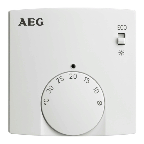
Illumra SR04 User manual

1
Copyright © 2009 ILLUMRA. All rights reserved. Contact ILLUMRA: T: (801) 349-1200 | F: (801) 653-4257 | [email protected] | www.ILLUMRA.com AHD0255A
Always follow local electrical codes when installing this device. Installation should be performed by a qualied technician.
ILLUMRA products are intended only for use indoors, in dry locations, and with permanantly installed xtures.
ILLUMRA products should NOT be installed in a location where the unit will be in close proximity to the light bulb(s)
or other sources of heat, such as above a ceiling hugger xture, particularly with higher wattage loads. Installation in
close proximity to light bulbs or other heat sources may subject the receiver to temperatures exceeding the operating
temperature rating (see “Operating Temperature” on specications table).
Installation in metallic enclosures or near large metal objects will typically reduce radio range.
SELECT 1 OF THE FOLLOWING APPLICATIONS:
Adhesive mount
Note: If you are unsure if a desired location is suitable for the Temperature Sensor, test its functionality in that location
before installation. For guidelines on choosing a location refer to the sections in these instructions entitled “Selecting
the Mounting Place for Solar Energy Storage” and “Transmission Range.”
Step 1: Peel the lining paper off of one side of the square of mounting tape (B) included.
Step 2: Afx the exposed mounting surface squarely to the back of the Sensor.
Step 3: Peel the lining paper off the other side of the square mounting tape.
Step 4: Afx the exposed mounting surface squarely to the desired location.
Screw mount
Step 1: Remove the backplate as shown below.
Open cover here
Step 2: Mount the backplate to the wall using appropriate screws (not included).
(Dimensions in mm)
Step 3: Snap the Sensor onto the backplate.
■
■
■
■
Installation Guide
SR04 - Room temperature sensor only
SR04P - Room temperature sensor with set point adjustment
SR04PT - Room temperature sensor with set point adjustment,
presence key (pictured)
SR04PST - Room temperature sensor with set point adjustment,
presence key, fan speed switch)
SR04P MS - Room temperature sensor with set point
adjustment, slide switch O/I
SR04 rH (Room sensor humidity/temperature)
SR04P rH - Room sensor humidity/temperature with set point
adjustmen)
SR04PT rH (Room sensor humidity/temperature with set point
adjustment, presence key)
SR04P MS rH (Room sensor humidity/temperature with set point
adjustment, slide switch O/I)
Wireless Room
Temperature Sensor
Optional: occupied button, slide
switch, set point, fan selector,
humidity sensor
Overview
The ILLUMRATM Wireless Temperature sensor detects the temperature of a room and transmits to compatible HVAC and/or humidity
controllers, and/or ventilation devices. Users can also adjust temperature settings manually through its optional set point dial. For use in
consistantly dark areas, it can be used with an optional lithium battery. Depending on the specic model, the SR04 comes equipped with
an integrated temperature sensor, humidity sensor, rotary knob for set pont adjustment, rotary nob for fan speed adjustment, and/or a
presence button or slide switch.
Compatible Devices
RF Serial Box; E3X-232FP
Ethernet Gateway; E3X-E18-XS1
More
Components Included
The following items are included with this product:
A -- (1) ILLUMRA Temperature Sensor
B -- (1) Square of mounting tape
Tools Needed for Installation
Screwdriver
Screws (if a screw mount is desired)
Needle-nose pliers (if you wish to change the Transmission Time)
Installation
To install the Temperature Sensor select a method from the options below. Follow the instructions for that method. For receiver
installation instructions, see appropriate installation guide(s).
CAUTION/NOTES:
■
■
■
■
■
■
■
■

2
Copyright © 2009 ILLUMRA. All rights reserved. Contact ILLUMRA: T: (801) 349-1200 | F: (801) 653-4257 | [email protected] | www.ILLUMRA.com AHD0255A
Selecting the Mounting Place for Optimum Solar Energy Storage
By means of the energy-optimized EnOcean radio technology used in Wireles Temperature Sensors, the Temperature Sensor supplies
itself with electric energy using a 2 cm2 solar cell and can work without batteries. Without the need to supply or change batteries, the
Sensors are environmentally sound and maintenance-free.
The solar-powered energy storage may need to be recharged after prolonged storage in darkness. Typically this is accomplished
automatically during the rst few operating hours in daylight. If the initial charging in the rst operating hours is not sufcient, the sensor
should reach its fully functional state in 3 to 4 days at the latest. The sensor will operate properly even in nighttime conditions after this
period of time.
To make sure the Wireless Room Temperature Sensor has enough ambient light to operate, mount the product in a suitable location.
When selecting the mounting place, consider the following:
The minimum illumination of 200Ix should be guaranteed at the mounting place for at least 3 to 4 hours every day, regardless of
whether this is articial light or daylight.
The Health and Safety at Work Act (UK) requires a minimum illumination of 500Ix for ofce workplaces.
The illumination should not exceed 1000Ix in the long term.
Mounting in any recess that is not illuminated sufciently in the course of a day should be avoided.
When using collimated articial light, the angle of incidence on the solar cell should not be too steep.
The sensors should preferably be mounted with the solar cell facing a window, but direct sunlight should be avoided. A position which
occasionally receives direct sun radiation could lead the device to report false temperature information.
Be sure that your location will not be obscured in shadow by any changes you may make to the room in the future.
If the ambient brightness is not sufcient
The sensor is equipped with a battery holder for use in consistently unlighted areas.
Battery to be used: Lithium battery, 3.6V/1.1Ah Type LS14250 / 0.5 AA
Operating time approx. 5 to 10 years, depending on the condition and discharge rate of the battery used.
In order to change the sensor from solar to battery mode, simply put the battery into the battery holder.
(
1. 2.
Open cover here
Open
bottom
Place battery in
battery holder
+ -
LEARN
Transmission Range
The type of material used in a building is important in evaluating the transmitting range. Some guide ranges:
Visual contacts: Typ. 30m range in passages, corridors. Up to 100m in halls
Rigypsum walls/wood: Typ. 30m range through max. 5 walls
Brick wall/Gas concrete: Typ. 20m range through max. 3 walls
Reinforced concrete/ceilings: Typ. 10m range through max. 1 ceiling
Supply blocks and lift shafts should be seen as a compartmentalisation
Other interference sources
Other devices that also operate with high-frequency signals (e.g. computers, audio/video systems, electronic transformers and ballasts,
etc.) are also sources of interference. Keep such devices at least 0.5 m away from the Temperature Sensor.
■
■
■
■
■
■
■
■
■
■
■
■
Programming
In order to use the Wireless Room Temperature Sensor, the device must be “learned” by the receiver. This is done automatically by
means of a “learn button” on the Sensor, or manually by input of the 32bit sensor ID and a special “learning procedure” between the
Sensor and a receiver. The respective details are described in the corresponding documentation of the receiver. The LEARN button
for the Temperature Sensor is located behind the back plate. See the section labeled “Selecting the Mounting Place for Optimum Solar
Energy Storage” on the left side of this page for a picture showing how to remove the backplate and for the location of the LEARN
button.
Temperature Sensing and Signal Transmission
There are two ways the Wireless Room Temperature Sensor can communicate temperature readings to other devices:
Event Controlled. When the Occupancy button on the front of the Temperature Sensor is pressed, the internal microprocessor
wakes up, detects a temperature, and sends a signal conveying that reading to the receiver.
Time Controlled. The internal microproccessor wakes up at a selected interval, collecting temperature data and sending it to the
receiver. If the temperature sensed is different that the previous reading by > 2%, the signal is sent immediately upon detection. If
temperature has not changed, a signal is automatically sent after the selected number of wake cycles.
Setting the Transmission Time
The factory settings program the Wireless Room Temperature Sensor to send a new temperature signal approximately every 16
minutes (assuming no temperature change is detected sooner). How often the Sensor sends a signal has a direct impact on its
energy use. Depending on the amount of light and energy available (or the desired life of a battery, if one is being used), it may be
advantageous to adjust this setting.
Three variables control the transmission time: T_Wake up, T_Interval, and T_Send.
T_Wake up. This determines how long the unit waits between each temperature reading to wake it back up for another.
T_Interval. This determines how many wake cycles the unit will perform before sending a new signal even though the temperature
has not changed.
T_Send. This is determined by multiplying T_Wake up and T_Interval together (T_Wake up x T_Interval = T_Send). It is the total
time between signals (assuming temperature change is not detected sooner).
To change the Transmission Time, follow these steps:
Step 1: Remove the unit from the backplate.
Step 2: Locate the jumpers. These are small black brackets placed over pins in the lower left corner of the Sensor (see below).
Step 3: Use a pair of needle-nose pliers to gently lift the jumpers off the pins and replace them in the proper formation to create
the desired settings (see table below). Be sure to keep any unused jumpers in a safe place.
Step 4: Re-attatch the unit to the backplate.
(rear view of Sensor)
Learn
TI TW
TW (T_Wake up)
=10 seconds
=100 seconds
TI (T_Interval)
=1 cycle
=10 cycles
=100 cylcles
Factory Settings
T_Wake up: 100 seconds T_Interval: 10 cycles.
(T_Wakeup 100 seconds) x (T_Interval 10 cycles) = T_Send: 1000 seconds or about 16 minutes.

Copyright © 2009 ILLUMRA. All rights reserved. Contact ILLUMRA: T: (801) 349-1200 | F: (801) 653-4257 | [email protected] | www.ILLUMRA.com AHD0255A
3
This device or certain aspects thereof is
protected by at least one U.S. or international
patent or has at least one such patent
application pending.
ILLUMRA is a trademark of Ad Hoc
Electronics, LLC. Other trademarks herein are
the property of their respective owners.
Dimensions (measurements in mm)
-
0
+
Contains FCC ID: S3N-SR04XX
Contains IC: 7953A-SR04XX
The enclosed device complies with Part 15 of the FCC
Rules. Operation is subject to the following two conditions:
(i.) this device may not cause harmful interference and (ii.)
this device must accept any interference received, including
interference that may cause undesired operation.
Warning: Changes or modications made to this equipment
not expressly approved by Thermokon may void the user’s
authority to operate this equipment.
This device complies with Industry Canada RSS-210 Issue 7.
Specications
Technology
Transmitting Frequency
Antenna
Transmitting Range
Temperature
Detection
Range
Resolution
Absolute Accuracy
Optional
Humidity
Sensor
Range
Resolution
Absolute Accuracy
1 Point Calibration
Optional
Set Point
Adjustment P
Range
Resolution
Rotary Switch S
Slide Swtch MS (optional with button T)
Measuring Value Detection
Sending Interval (defaults)
Energy Generator
Enclosure
Protection
Ambient Temperature
Transport
Weight
SR04PTxx
Enocean, STM
315.0 MHz
Type: Helix, Gain: -3dBi
approx 50-150 feet in buildings
0°C to 40°C
0.15 K
typ. +/-0.4K
0-100% rH
0.4% rH
+/-3% range
30%... 80%
50%
0 to 270° angle of rotation
1.1°
Number of switching steps 5 (A, 0, I, II, III)
Number of switching steps 2 (O/I)
Every 100 seconds
...every 100 seconds
if changes >0.8K
or >3° angle of rotation
or switch step rotary switch
or slide switch
...every 1000 seconds
if changes <0.8K
or <3° angle of rotation
Solar cell, internal goldcap, maintenance-free
ABS (ASA) color pure white similar to RAL 9010
IP20 according to EN60529
-25°C to 65°C
-25°C to 65° C / max. 70% rH, non-condensed
50g
This manual suits for next models
6
Table of contents
Popular Temperature Controllers manuals by other brands
Redsun
Redsun E200 User and installation guide
Vega Absolute
Vega Absolute VEGA TD-11 user manual

BREWHA Equipment
BREWHA Equipment ETC Faqs

Microm
Microm MIX-5251AP Installation and maintenance instructions

GUIDO RAYOS X
GUIDO RAYOS X NESTORET 5050 manual
Daikin
Daikin Altherma ERHQ011-014-016BA Installer's reference guide

