HP 697497-001 User manual

HP Ethernet 10Gb 2-port 560SFP+ Adapter
User Guide
Abstract
This document is for the person who installs, administers, and troubleshoots servers and storage systems. HP assumes you are qualified in the
servicing of computer equipment and trained in recognizing hazards in products with hazardous energy levels.
Part Number: 697497-001
May 2012
Edition: 1

© Copyright 2012 Hewlett-Packard Development Company, L.P.
The information contained herein is subject to change without notice. The only warranties for HP products and services are set forth in the express
warranty statements accompanying such products and services. Nothing herein should be construed as constituting an additional warranty. HP shall
not be liable for technical or editorial errors or omissions contained herein.
Microsoft® and Windows® are U.S. registered trademarks of Microsoft Corporation. Intel® is a trademark of Intel Corporation in the United States
and other countries.
Bluetooth® is a trademark owned by its proprietor and used by Hewlett-Packard Company under license.

Contents 3
Contents
Technician notes........................................................................................................................... 4
Warnings, cautions, and notes.................................................................................................................... 4
Downloading files ..................................................................................................................................... 4
HP contact information............................................................................................................................... 5
Introduction.................................................................................................................................. 6
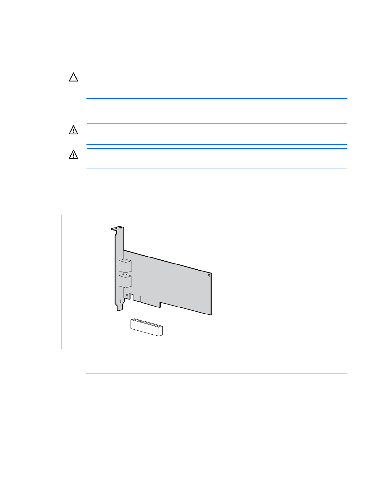
Overview ................................................................................................................................................. 6
LEDs ........................................................................................................................................................ 6
Installing an adapter ..................................................................................................................... 7
Installation overview .................................................................................................................................. 7
Preventing electrostatic discharge ................................................................................................................ 7
Installing an adapter in a server .................................................................................................................. 8
Installing a low profile bracket .................................................................................................................... 8
Connecting the network cable..................................................................................................................... 9
Specifications............................................................................................................................. 10
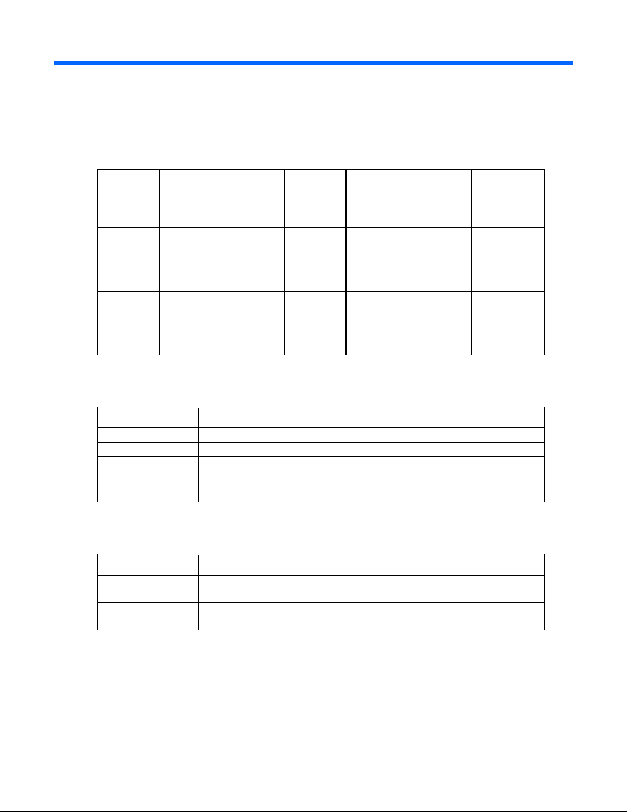
Cable specifications ................................................................................................................................ 10
General specifications ............................................................................................................................. 10
Compliance............................................................................................................................................ 10
Power and environmental specifications ..................................................................................................... 11
Regulatory compliance notices ..................................................................................................... 12
Regulatory compliance identification numbers............................................................................................. 12
Federal Communications Commission Notice.............................................................................................. 12
Modifications.......................................................................................................................................... 12
European Union regulatory notice ............................................................................................................. 12
Canadian notice (Avis Canadien).............................................................................................................. 13
Korean class B notice............................................................................................................................... 13
Japanese class B notice............................................................................................................................ 13
Disposal of waste equipment by users in private households in the European Union......................................... 13
Electrostatic discharge................................................................................................................. 15
Preventing electrostatic discharge .............................................................................................................. 15
Grounding methods to prevent electrostatic discharge.................................................................................. 15
Acronyms and abbreviations........................................................................................................ 16
Documentation feedback ............................................................................................................. 17

Technician notes 4
Technician notes
Warnings, cautions, and notes
WARNING: Only authorized technicians trained by HP should attempt to repair this equipment.
All troubleshooting and repair procedures are detailed to allow only subassembly/module-level
repair. Because of the complexity of the individual boards and subassemblies, no one should
attempt to make repairs at the component level or to make modifications to any printed wiring
board. Improper repairs can create a safety hazard.
WARNING: To reduce the risk of electric shock, personal injury, and damage to the equipment:
•Do not attempt to service any parts of the equipment other than those specified in the following
procedure. Any other activities may require that you shut down the server and remove the
power cord.
•Installation and maintenance of this product must be performed by individuals who are
knowledgeable about the procedures, precautions and hazards associated with the product.
WARNING: To reduce the risk of electric shock or damage to the equipment:
•Do not disable the power cord grounding plug. The grounding plug is an important safety
feature.
•Plug the power cord into a grounded (earthed) electrical outlet that is easily accessible at all
times.
•Unplug the power cord from the power supply to disconnect power to the equipment.
•Do not route the power cord where it can be walked on or pinched by items placed against it.
Pay particular attention to the plug, electrical outlet, and the point where the cord extends from
the server.
This symbol indicates the presence of a hot surface or hot component. If this surface is
contacted, the potential for injury exists.
WARNING: To reduce the risk of injury from a hot component, allow the surface to cool
before touching.
CAUTION: To properly ventilate the system, you must provide at least 7.6 cm (3.0 in) of
clearance at the front and back of the server.
CAUTION: The server is designed to be electrically grounded (earthed). To ensure proper
operation, plug the AC power cord into a properly grounded AC outlet only.
NOTE: Any indications of component replacement or printed wiring board modifications may
void any warranty.
Downloading files
1. Go to the HP website (http://www.hp.com/#Support).

Technician notes 5
2. Select Download drivers and software (and firmware).
3. Type the adapter name in the For product box and then click Go. For example, type HP Ethernet 10Gb
2-port 560SFP+.
4. Download the drivers, firmware, or documentation as needed.
HP contact information
For United States and worldwide contact information, see the Contact HP website
(http://www.hp.com/go/assistance).
In the United States:
•To contact HP by phone, call 1-800-334-5144. For continuous quality improvement, calls may be
recorded or monitored.
•If you have purchased a Care Pack (service upgrade), see the Support & Drivers website
(http://www8.hp.com/us/en/support-drivers.html). If the problem cannot be resolved at the website,
call 1-800-633-3600. For more information about Care Packs, see the HP website
(http://pro-aq-sama.houston.hp.com/services/cache/10950-0-0-225-121.html).

Introduction 6
Introduction
Overview
The HP Ethernet 10Gb 2-port 560SFP+ Adapter is a dual-port, 10 Gb SFP+ adapter that supports Gen7 and
Gen8 ML/DL/SL ProLiant servers and uses the Intel 82599 (Niantic) chipset.
For more information about the HP Ethernet 10Gb 2-port 560SFP+ Adapter, see the HP website
(http://www.hp.com/go/proliantnics).
LEDs
The HP Ethernet 10Gb 2-port 560SFP+ Adapter has two ports with LEDs for Link (L) and Activity (A) for each
port. A standard-height bracket is shown in the following illustration with SFP+ ports and LEDs.
The HP Ethernet 10Gb 2-port 560SFP+ Adapter LEDs operate as described in the following table.
Item LED Status Description
1 Link Off No link to the adapter is established. The adapter is not
receiving power or the cable connection is faulty.
— — On (Amber) Link to the adapter is established at 10 Gb/s. The
adapter is receiving power and the cable connection is
good.
— — On (Green) Link to the adapter is established at 1 Gb/s. The
adapter is receiving power and the cable connection is
good.
2 Activity Off Indicates no network activity on the link.
— — On (Green) Indicates network activity on the link. The adapter is
sending or receiving network data at up to 10 Gb/s.

Installing an adapter 7
Installing an adapter
Installation overview
This section describes installation precautions, how to install the adapter, and how to connect the network
cable.
WARNING: To reduce the risk of personal injury or damage to the equipment, consult the safety
information and user documentation provided with the server before attempting the installation.
Some servers contain high energy, high circuits, moving parts (such as fan blades), or any
combination of these hazards, that may be exposed if covers and access panels are removed
while the product is powered. These products are intended to be serviced only by qualified
personnel who have been trained to deal with these hazards. Do not remove enclosures or
attempt to bypass any interlocks that may be provided for the purpose of guarding against these
hazardous conditions.
WARNING: Installation of this adapter should be performed by individuals who are both
qualified in the servicing of computer equipment, and trained in the hazards associated with
products capable of producing hazardous energy levels.
This adapter is intended to be installed in Certified (UL or CSA) ITE equipment having instructions
for adding and removing user installed components such as PCI, PCI-X, and PCI Express devices.
Refer to the equipment instructions to verify that it is suitable for user installed components and that
it has the power capacity to support all of the installed components.
NOTE: Before removing the cover of your server, refer to the HP documentation for the proper
methods for installing a PCI Express card and avoiding electric shock hazards.
Preventing electrostatic discharge
To prevent damaging the system, be aware of the precautions you need to follow when setting up the system
or handling parts. A discharge of static electricity from a finger or other conductor may damage system
boards or other static-sensitive devices. This type of damage may reduce the life expectancy of the device.
To prevent electrostatic damage:
•Avoid hand contact by transporting and storing products in static-safe containers.
•Keep electrostatic-sensitive parts in their containers until they arrive at static-free workstations.
•Place parts on a grounded surface before removing them from their containers.
•Avoid touching pins, leads, or circuitry.
•Always be properly grounded when touching a static-sensitive component or assembly.

Installing an adapter 8
Installing an adapter in a server
For additional information on how to safely install a PCI Express card in the server, see the HP ProLiant server
documentation.
CAUTION: If the server is not PCI Hot Plug compliant, power it down and disconnect the power
cord from the power outlet before removing the server access panel. Failure to do so may damage
the adapter or server.
1. Power down the server.
2. Remove the power cord and server access panel.
WARNING: To reduce the risk of personal injury from a hot component, allow the surface of the
option card to cool before touching it.
WARNING: To reduce the risk of personal injury from hot surfaces, allow the drives and the
internal system components to cool before touching them.
3. Identify the PCIe expansion slot in which the adapter is to be installed. If a low profile option slot is to
be used, install the low profile bracket onto the adapter.
4. Remove the expansion slot cover from the PCI Express slot.
5. Firmly seat the adapter in the PCI Express slot.
NOTE: For 1U type servers you may need to replace the standard profile bracket with a low
profile bracket. See Installing a low profile bracket (on page 8).
6. Install the access panel, and then connect the power cord.
Installing a low profile bracket
You may have to install a low profile bracket to complete the product installation. The low profile bracket
replaces the existing standard profile bracket shipped on the product.
To install a low profile bracket:

Installing an adapter 9
1. Using a correctly sized slotted screwdriver, carefully remove the two board lock screws located at the
top and bottom of the connector.
2. Remove the standard profile bracket and place the low profile bracket over the connector. Be careful
not to damage the connector or bind the low profile bracket to the connector.
Connecting the network cable
The HP Ethernet 10Gb 2-port 560SFP+ has two SFP+ ports. These ports support either of the following:
•DAC cables
•Optical Modules to be used with fiber optic cables
For the maximum cable length supported, see "Cable specifications (on page 10)".
To connect the HP Ethernet 10Gb 2-port 560SFP+ to the network:
1. Orient the SFP+ optical module or DAC cable so that the edge connector on the edge of the circuit
board is located closest to the option card circuit board.
2. Install the SFP+ optical module or DAC cable until the connector seats fully into the SFP+ socket, clicks
into place, and latches securely.
3. If an optical module is used, remove the protective cover, and then connect the fiber optic cable.

Specifications 10
Specifications
Cable specifications
SFP+
module type
Cable
Connector
Type
Wavelength
(nm), type of
cable
Core Size
(microns,
µm)
Cable grade Minimum
modal
bandwidth
(MHz-km)
Maximum
Cable Length
(meters)
10GBASE-SR
(short range)
Optical
Module
LC 850,
Multi-Mode
Fiber (MMF)
62.5
62.5
50
50
50
(“FDDI”)
OM1
OM2
OM3
160
200
400
500
2000
26
33
66
82
300
10GBASE-CR
with Direct
Attached
Copper
(DAC) cable
SFP+ N/A, Twin
Axial Copper 24 to 28
AWG,
depending on
length and
manufacturer
N/A N/A 7
General specifications
Specification Value
Controller Intel 82599 (Niantic)
Data rate 10 Gb/s per port, 20 Gb/s combined, full-duplex
PCI bus PCI Express x8 Gen3
Connectors
Two 10 Gb SFP+
Dimensions (LxW) 13.21 cm x 6.89 cm (5.2 inches x 2.7 inches) without bracket
Compliance
Compliance Standard
IEEE IEEE802.3, IEEE802.3ap, IEEE802.3xx, IEEE802.2x, IEEE802.3ad, 802.1Qaz,
802.1Qau, 802.1Qbb, 802.1Qbg, 802.1Qbh
Safety UL Mark (US and Canada)
EN 60950

Specifications 11
Compliance Standard
Other PCIe v3.0
RoHS 6 of 6
IPv4, IPv6
CE
Microsoft Windows Hardware Quality Labs
Server Design Guide version 3.0
SNMP
IPv4, TCP and UDP Checksum Offload
IPv4/IPv6 TCP, Large Send Offload
Receive-Side Scaling
Jumbo Frames up to 9000 Bytes
Power and environmental specifications
Specification Value
Operating Temperature—0° to 55° C (32° to 131° F)
Humidity—10 to 90% relative humidity, non-condensing
Non-operating Temperature—-65° to 85° C (-85° to 185° F)
Humidity—5 to 95% relative humidity, non-condensing
Power 4 W typical, 9 W maximum

Regulatory compliance notices 12
Regulatory compliance notices
Regulatory compliance identification numbers
For the purpose of regulatory compliance certifications and identification, this product has been assigned a
unique regulatory model number. The regulatory model number can be found on the product nameplate
label, along with all required approval markings and information. When requesting compliance information
for this product, always refer to this regulatory model number. The regulatory model number is not the
marketing name or model number of the product.
Federal Communications Commission Notice
This equipment has been tested and found to comply with the limits for a Class B digital device, pursuant to
Part 15 of the FCC Rules. These limits are designed to provide reasonable protection against harmful
interference in a residential installation. This equipment generates, uses, and can radiate radio frequency
energy and, if not installed and used in accordance with the instructions, may cause harmful interference to
radio communications. However, there is no guarantee that interference will not occur in a particular
installation. If this equipment does cause harmful interference to radio or television reception, which can be
determined by turning the equipment off and on, the user is encouraged to try to correct the interference by
one or more of the following measures:
•Reorient or relocate the receiving antenna.
•Increase the separation between the equipment and receiver.
•Connect the equipment into an outlet on a circuit that is different from that to which the receiver is
connected.
•Consult the dealer or an experienced radio or television technician for help.
Modifications
The FCC requires the user to be notified that any changes or modifications made to this device that are not
expressly approved by Hewlett-Packard Company may void the user’s authority to operate the equipment.
European Union regulatory notice
Products bearing the CE marking comply with the following EU Directives:
•Low Voltage Directive 2006/95/EC
•EMC Directive 2004/108/EC
•Ecodesign Directive 2009/125/EC, where applicable
CE compliance of this product is valid if powered with the correct CE-marked AC adapter provided by HP.
Compliance with these directives implies conformity to applicable harmonized European standards
(European Norms) that are listed in the EU Declaration of Conformity issued by HP for this product or product

Regulatory compliance notices 13
family and available (in English only) either within the product documentation or at the following HP website
(http://www.hp.eu/certificates) (type the product number in the search field).
The compliance is indicated by one of the following conformity markings placed on the product:
For non-telecommunications products and for EU harmonized telecommunications products, such as
Bluetooth® within power class below 10mW.
For EU non-harmonized telecommunications products (If applicable, a 4-digit notified body number is
inserted between CE and !).
Please refer to the regulatory label provided on the product.
The point of contact for regulatory matters is Hewlett-Packard GmbH, Dept./MS: HQ-TRE, Herrenberger
Strasse 140, 71034 Boeblingen, GERMANY.
Canadian notice (Avis Canadien)
This Class B digital apparatus meets all requirements of the Canadian Interference-Causing Equipment
Regulations.
Cet appareil numérique de la classe B respecte toutes les exigences du Règlement sur le matériel brouilleur
du Canada.
Korean class B notice
Japanese class B notice
Disposal of waste equipment by users in private
households in the European Union

Regulatory compliance notices 14
This symbol on the product or on its packaging indicates that this product must not be disposed of
with your other household waste. Instead, it is your responsibility to dispose of your waste
equipment by handing it over to a designated collection point for the recycling of waste electrical
and electronic equipment. The separate collection and recycling of your waste equipment at the
time of disposal will help to conserve natural resources and ensure that it is recycled in a manner
that protects human health and the environment. For more information about where you can drop
off your waste equipment for recycling, please contact your local city office, your household
waste disposal service or the shop where you purchased the product.

Electrostatic discharge 15
Electrostatic discharge
Preventing electrostatic discharge
To prevent damaging the system, be aware of the precautions you need to follow when setting up the system
or handling parts. A discharge of static electricity from a finger or other conductor may damage system
boards or other static-sensitive devices. This type of damage may reduce the life expectancy of the device.
To prevent electrostatic damage:
•Avoid hand contact by transporting and storing products in static-safe containers.
•Keep electrostatic-sensitive parts in their containers until they arrive at static-free workstations.
•Place parts on a grounded surface before removing them from their containers.
•Avoid touching pins, leads, or circuitry.
•Always be properly grounded when touching a static-sensitive component or assembly.
Grounding methods to prevent electrostatic discharge
Several methods are used for grounding. Use one or more of the following methods when handling or
installing electrostatic-sensitive parts:
•Use a wrist strap connected by a ground cord to a grounded workstation or computer chassis. Wrist
straps are flexible straps with a minimum of 1 megohm ±10 percent resistance in the ground cords. To
provide proper ground, wear the strap snug against the skin.
•Use heel straps, toe straps, or boot straps at standing workstations. Wear the straps on both feet when
standing on conductive floors or dissipating floor mats.
•Use conductive field service tools.
•Use a portable field service kit with a folding static-dissipating work mat.
If you do not have any of the suggested equipment for proper grounding, have an authorized reseller install
the part.
For more information on static electricity or assistance with product installation, contact an authorized
reseller.

Acronyms and abbreviations 16
Acronyms and abbreviations
CSA
Canadian Standards Association
DAC
direct attach cable
IPv4
Internet Protocol version 4
IPv6
Internet Protocol version 6
PCIe
peripheral component interconnect express
PCI-X
peripheral component interconnect extended
RoHS
Restriction of Hazardous Substances
SFP+
small form-factor pluggable - plus
UDP
User Datagram Protocol

Documentation feedback 17
Documentation feedback
HP is committed to providing documentation that meets your needs. To help us improve the documentation,
Include the document title and part number, version number, or the URL when submitting your feedback.
Table of contents
Other HP Adapter manuals

HP
HP 411508-B21 - Smart Array E200/128 BBWC Controller... Reference manual

HP
HP FlexFabric 534M User manual

HP
HP StorageWorks 2000sa Quick reference guide

HP
HP Flex-10 10Gb 2-port 552M User instructions

HP
HP 647594-B21 User manual

HP
HP 571SFP User manual

HP
HP Model 744 - VME Workstation Reference guide

HP
HP 381513-B21 - Smart Array P800 Controller... User manual

HP
HP 629135-B21 User manual

HP
HP AH226A - Smart Array E500/256MB Controller... Installation instructions