HP RP3 Retail System, Model 3100 719219-001 page2
Password Security
Establishing a Setup or Power-On password:
1. Turn on or restart the computer.
2. As soon as the computer turns on, press the Esc key while “Press the ESC key for Startup
Menu” message is displayed at the bottom of the screen.
3. Press the F10 key to enter Computer Setup.
4. To establish Setup password, select Security > Setup Password and follow the instructions.
- or -
To establish a Power-On password, select Security > Power-On Password and follow the
instructions on the screen
5. Before exiting, click File > Save Changes and Exit.
Resetting a Setup or Power-On password:
1. Turn off the computer and disconnect the power cord from the power outlet.
2. Remove the access panel.
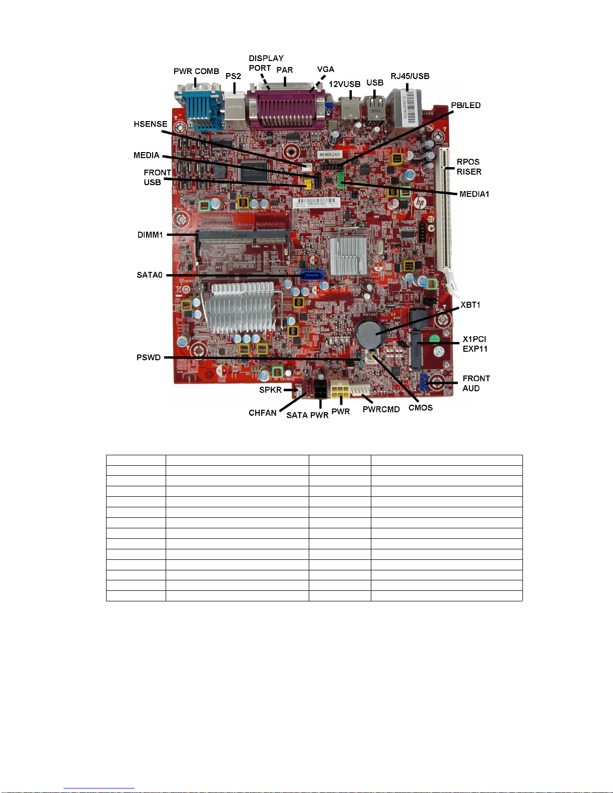
3. On the system board, locate the header labeled PSWD.
4. Remove the jumper from the header.
5. Replace the jumper.
6. Replace the chassis access panel and reconnect the power cord.
7. Turn on the computer and allow it to start.
Clearing CMOS
1. Turn off the computer and disconnect the power cord from the power outlet.
2. Remove the access panel.
3. On the system board, press and hold the CMOS button for 5 seconds.
4. Replace the chassis access panel and reconnect the power cord.
5. Turn on the computer and allow it to start.
Miscellaneous Parts
1 Fan assembly 682431-001
2 Speaker 647447-001
3 Antenna kit for use with WLAN modules 711789-001
* Hard drive grommet 594220-001
* Rubber feet 583654-001
* Cover, powered serial port 353054-001
* Mouse, PS2, optical 609250-001
* Mouse, washable 619580-001
* Mouse, optical, black 537749-001
* Mouse, laser, black 570580-001
*Not shown
Diagnostic LEDs
LED Color LED Activity State/Message
Power Green On Computer on
Power Green 1 blink every 2 seconds. Normal Suspend Mode.
Power Red 1 blink every second followed
by a 2 second pause. CPU thermal shutdown.
Power Red 3 blinks, 1 blink every second
followed by a 2 second pause. Processor not installed.
Power Red 4 blinks, 1 blink every second
followed by a 2 second pause. Power failure (power supply over-
load).
Power Red 5 blinks, 1 blink every second
followed by a 2 second pause. Pre-video memory error.
Power Red 6 blinks, 1 blink every second
followed by a 2 second pause. Pre-video graphics error.
Power Red 7 blinks, 1 blink every second
followed by a 2 second pause. System board failure (ROM).
Power Red 8 blinks, 1 blink every second
followed by a 2 second pause. Invalid ROM based on Checksum.
Power Red 9 blinks, 1 blink every second
followed by a 2 second pause. System powers on but is unable to
boot.
Power Red 10 blinks, 1 blink every second
followed by a 2 second pause. Bad option card.
Power Red 12 blinks, 1 blink every second
followed by a 2 second pause.
Beeps stop after a third itera-
tion and computer reboots.
Health timer expired.
none none System does not power on and
LEDs are not flashing. System unable to power on.
Computer Setup Menu
Heading Option/Description
File System Information - Lists the following main system specifications:
• Product name
• SKU number (some models)
• Processor type/speed/stepping
• Cache size (L1/L2/L3)
• Installed memory size/speed/chan
• Integrated MAC Address
• System BIOS
• Chassis serial number
• Asset tracking number
• ME firmware version
• ME Management mode
About - Displays copyright notice.
Set Time and Date - Allows you to set system time and date.
Flash System ROM - Allows you to select a drive containing a new BIOS.
Replicated Setup - Save to Rmvble Media and Restore from Rmvble Media
Default Setup: Save Current Settings as Default, Restore Factory Settings as Default
Apply Defaults and Exit - Applies the selected default settings and clears any
established passwords.
Ignore Changes and Exit - Exits Computer setup without saving changes.
Save Changes and Exit - Saves changes to system configuration or default
settings and exits Computer Setup.
Storage Device Configuration - Lists all installed BIOS-controlled storage devices.
The following options are available:
• CD-ROM - Let you view drive size, model, firmware version, serial
number, connector color.
• Hard Disk - Let you view drive size, model, firmware version, serial
number, connector color, SMART. Also lets you set Translation Mode
(Automatic, Bit-Shift, LBA Assisted, User, and Off).
• Diskette Drive - model and firmware version.
• SATA Defaults - lets you set Translation Mode (Automatic, Bit-Shift,
LBA Assisted, User, and Off).
• eSATA port - Allows you to set a SATA port as an eSATA port for use
with an external drive.
• SATA Emulation - IDE, RAID, or AHCI.
• Removable Media Boot - Enables/disables ability to boot the system
from removable media.
• Max eSATA Speed - Allows you to choose 1.5 Gbps or 3.0 Gbps as the
maximum eSATA speed.
DPS Self-Test - Allows you to execute self-tests on ATA hard drives.
Boot Order - Allows you to specify boot order.
• Shortcut to Temporarily Override Boot Order
Security Setup Password - Allows you to set and enable the setup (Admin) password.
Power-On Password - Allows you to set and enable power-on password.
Password Options - When any password exists allows you to lock legacy
resources, enable/disable Setup Browse Mode, set password prompt, enable/
disable network server mode, specify password requirement for warm boot,
and set stringent passwords.
Smart Cover (some models) - Allows you to lock/unlock cover lock and set
status of cover removal sensor.
Device Security - Allows you to set Device Available/Device Hidden for:
embedded security devices, serial and parallel ports, system audio, network
controller, and SATA ports.
USB Security - Allows you to set Device Available/Device Hidden for front
USB ports 1-4, rear USB ports 1-6, accessory USB ports 1-4.
Slot Security - Allows you to disable any PCI or PCI Express slot.
Network Boot - Enables/disables boot from OS (NIC models only).
System IDs - Allows you to set Asset tag, Ownership tag, Chassis serial
number or UUID, and keyboard locale setting.
System Security (some models) - Allows you to enable/disable:
• Data Execution Prevention (enable/disable)
• Virtualization Technology (VTx) (enable/disable)
• Virtualization Technology Directed I/O (VTd) (enable/disable)
• Intel TXT (LT) (enable/disable)
• Embedded Security Device Support (enable/disable)
• OS management of Embedded Security Device (enable/disable)
• Reset of Embedded Security Device through OS (enable/disable)
DriveLock Security - Assign/modify master or user password for hard
drives.
Power OS Power Management - Allows you to enable/disable Runtime Power Man-
agement, Idle Power Savings, Unique Sleep State Blink Rates.
Hardware Power Management - Allows you to enable/disable SATA bus
power management and S5 maximum power savings.
Thermal - Allows you to control minimum fan speed.
Advanced Power-On Options - Allows you to set:
• POST mode-QuickBoot, FullBoot, Clear Memory, FullBoot every x days
• POST messages - Enable/disable
• Press the ESC key for Startup Menu - Enable/disable
• Option ROM prompt - Enable/disable
• After Power Loss - Off/on/previous state
• POST Delay - None, 5, 10, 15, or 20 seconds
• System Recovery Boot Support - Enable/disable
• Remote Wakeup Boot Source - Remote server/local hard drive
• Bypass F1 Prompt on Configuration Changes - Enable/disable
BIOS Power-On - Allows you to set the computer to turn on at a preset time.
Onboard Devices - Allows you to set:
• resources or disable Legacy devices
• serial port A-D voltage settings - set to 0V, +5V, +12V
Bus Options (some models) - Allows you to enable/disable PCI SERR# Gen-
eration and PCI VGA palette snooping.
Advanced (con-
tinued)Device Options - Allows you to set:
• Turbo Mode - enable/disable
• Printer Mode - Bi-Directional, EPP & ECP, Output Only
• Num Lock State at Power-on - off/on
• Integrated Video - enable/disable
• Internal Speaker - enable/disable
• NIC Option ROM Download - enable/disable
• Multi-Processor - enable/disable
• Hyper-threading - enable/disable
VGA Configuration - Displayed only if there are multiple PCI video adapters
in the system. Allows you to specify which VGA controller will be the
“boot” or primary VGA controller.
AMT Configuration - Allows you to set:
• AMT-enable/disable functions of the embedded Management Engine
(ME) such as Active Management Technology (AMT).
• Unconfigure AMT/ME-unconfigure any provisioned management set-
tings for AMT.
• Watchdog Timer-set amount of time for a operating system and BIOS
watchdog alert to be sent if the timers are not deactivated.