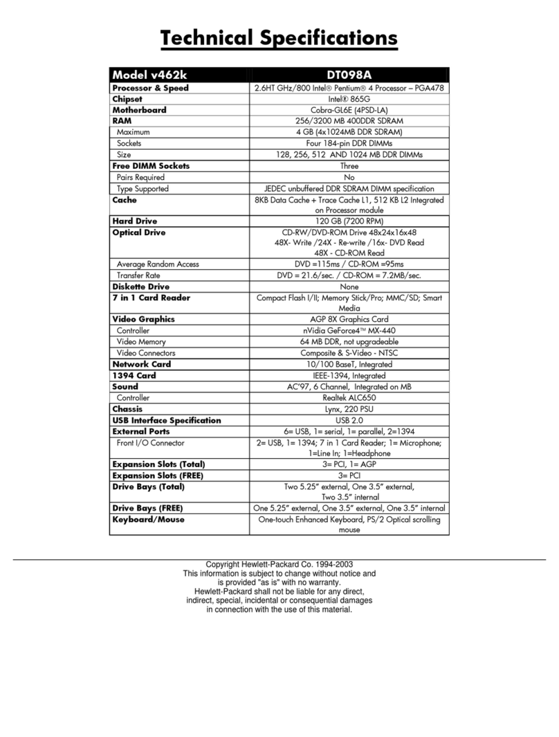
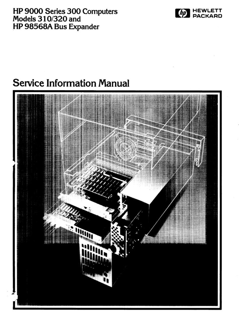
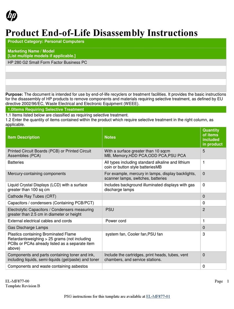
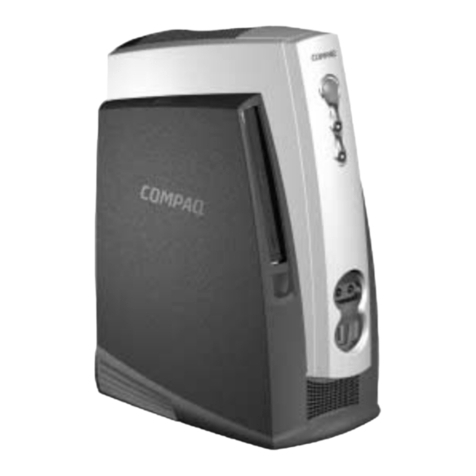
HP Compaq SP700 User manual

3-1
Compaq Professional Workstation SP700 Maintenance and Service Guide
Chapter 3
Removal and Replacement Procedures
This chapter provides subassembly/module-level removal and replacement procedures for the
Compaq Professional Workstation SP700.
After completing all necessary removal and replacement procedures, run the Compaq Setup and
Diagnostics program to verify that all components are operating properly.
Serial Number
Provide the computer serial number to Compaq whenever you request information or order spare
parts. The serial number is located just above the right top side of the side access panel ➊and on
the rear of the workstation 2.
For asset control, the serial number is also embedded in the EPROM on the system board. If the
system board is replaced with a spare part from Compaq, an invalid serial number condition will
be reported during POST. To clear the condition, reenter the original serial number through
Computer Setup.
NOTE: If a system board from another workstation is installed, POST recognizes the serial
number as a valid number.
1
2
Figure 3-1. Serial number locations

3-2 Removal and Replacement Procedures
Service Preparations
Before beginning any of the removal and replacement procedures, complete the
following steps:
CAUTION: The power supply in the Compaq Professional Workstation SP700 has
an auxiliary power section. This section is always active as long as the unit is
plugged into a live AC outlet. Be sure to turn off the switch and unplug the power
cord before performing any service work.
CAUTION: Electrostatic discharge can damage electronic components of the
workstation. Before beginning these procedures, be sure you are properly
grounded. See “Electrostatic Discharge Information” in Chapter 2 for more
information.
1. Turn off the workstation.
2. Disconnect the power cord from the grounded AC outlet and then from the workstation.
3. Turn off all peripheral devices and disconnect cables from the rear of the workstation.
4. Remove the cable lock in order to access internal components. Refer to the following
section for instructions on how to remove the cable lock.
NOTE: In some of the removal procedures in this chapter, you will be asked to remove the
workstation feet and lay the workstation on its side when servicing some of the internal
components.
NOTE: For more information on preparing the workstation for service, see Chapter 2.

3-3
Compaq Professional Workstation SP700 Maintenance and Service Guide
Cable Lock
The workstation comes standard with a cable lock provision for attaching a padlock and/or cable
lock. If installed, the locks must be removed before accessing internal components.
To remove the lock:
1. Unlock and remove the cable lock and/or the padlock.
2. Remove the security bracket (plate) seated over the cable lock bracket.
3. Unfasten the retaining screw to release the cable lock bracket.
Figure 3-2. Removing the padlock

3-4 Removal and Replacement Procedures
Workstation Feet
NOTE: Not all procedures in this chapter require the removal of the workstation feet. Be sure to
thoroughly read each removal and replacement procedure before attempting to access the
workstation’s internal components.
To remove the workstation feet:
1. Perform the service preparations shown on page 3-2.
2. Remove the screws that secure the feet.
3. Remove the workstation feet.
Figure 3-3. Removing the workstation feet
To replace the feet, reverse the above procedure.

3-5
Compaq Professional Workstation SP700 Maintenance and Service Guide
Side Access Panel
CAUTION: Do not operate the workstation with the side access panel removed.
The panel is an integral part of the cooling system; removing it while the system is
running may adversely affect data integrity.
To remove the side access panel:
1. Perform the service preparations shown on page 3-2.
2. Loosen the four rear panel thumbscrews, then slide the access panel off.
Figure 3-4. Loosening the thumbscrews and removing the side access panel
WARNING: To reduce the risk of personal injury from hot surfaces, allow the
internal system components to cool before touching.
IMPORTANT: When replacing the side access panel, be sure to tighten all four
thumbscrews.
NOTE: The hood label attached to the inside of the side access panel provides system
configurations and the installation of additional components.
To replace the side access panel:
1. Be sure all grounding clips and EMI gaskets (shielding strips) are in place.
2. Slide the side access panel in at an angle on one side, drop it into place, then slide it into
the unit completely.
3. Tighten the rear panel thumbscrews.

3-6 Removal and Replacement Procedures
Front Bezel
The front bezel is mounted to the chassis with release levers that are integrated into the bezel.
To remove the front bezel:
1. Perform the service preparations on page 3-2.
2. Remove the side access panel.
3. Depress the front bezel release latches 1and remove the front bezel 2.
COMPACT
1
2
Figure 3-5. Removing the front bezel
To replace the front bezel:
1. Line up the hinges and release latches with the appropriate slots on the front of the
chassis.
2. Press the bezel in to secure the release latches.

3-7
Compaq Professional Workstation SP700 Maintenance and Service Guide
Blank Drive Bezel
To remove the blank drive bezel from the front bezel:
1. Perform the service preparations shown on page 3-2.
2. Remove the following components:
❏ side access panel
❏ front bezel
3. Remove the screws that secure the blank drive bezel, then remove the blank bezel from
the front bezel.
Figure 3-6. Removing the blank bezel
To replace the blank drive bezel, reverse the above procedure.

3-8 Removal and Replacement Procedures
EMI/Cooling Shield
An EMI/cooling shield covers bays 5 and 6 to provide proper cooling and EMI protection. To
remove the EMI/cooling shield:
1. Perform the service preparations on page 3-2.
2. Remove the following components:
❏ side access panel
❏ front bezel
3. Remove the two screws that connect the EMI/cooling shield to the front of the chassis.
4. Remove the EMI/cooling shield from the drive slot.
COMPACT
Figure 3-7. Removing the EMI/cooling shield
IMPORTANT: You will need to replace the shield after the drive is installed in the bay.
To replace the EMI/cooling shield, reverse the above procedure.

3-9
Compaq Professional Workstation SP700 Maintenance and Service Guide
Speaker
To remove the speaker:
1. Perform the service preparations shown on page 3-2, remove the workstation feet, and
place the workstation on its side.
2. Remove the side access panel.
3. Unplug the speaker connector from the system board 1, and remove the cable from the
clip.
4. Remove the four T-15 screws securing the front of the speaker to the chassis 2.
5. Remove the speaker from the workstation by sliding it back, then lifting it up and out of
the chassis 3.
2
1
3
Figure 3-8. Removing the speaker
To replace the speaker, reverse the above procedure.

3-10 Removal and Replacement Procedures
I/O Bracket Assembly (Expansion Board
Assembly)
The I/O bracket assembly contains a backplane board (also called riser card), card guide, and
any expansion boards. To remove the I/O bracket assembly:
1. Perform the service preparations shown on page 3-2, remove the workstation feet, and
place the workstation on its side.
2. Remove the side access panel.
CAUTION: The power supply in the Compaq Professional Workstation SP700
contains an auxiliary power section. Be sure the power switch is off and the unit is
unplugged before removing the I/O bracket assembly in the next step.
3. Grasp the I/O bracket assembly and pull it out of the chassis.
Figure 3-9. Removing the I/O bracket assembly

3-11
Compaq Professional Workstation SP700 Maintenance and Service Guide
Important Guidelines for I/O Bracket Assembly (Expansion
Board Assembly) Replacement
To replace the I/O bracket assembly, you MUST follow these steps:
1. Grasp the assembly and insert it into the chassis and connector on the system board. Press
firmly on the I/O bracket assembly, where the backplane is connected to the system
board.
2. After connecting the power cord to the grounded AC outlet and to the workstation, DO
NOT turn on the power switch if the power LED is a steady amber color. A steady amber
color indicates that the I/O bracket assembly, processor(s), or terminator board (if
installed) is not seated properly.
Disconnect the power cord from the grounded AC outlet, reseat the I/O bracket assembly,
processor(s), or terminator board (if installed), then reconnect the power cord. Once these
components are seated properly and the power LED is a steady green color, disconnect
the power cord once again before continuing with additional service.
WARNING: DO NOT turn on the power switch unless the I/O bracket assembly,
processor(s), and terminator board (if installed) are seated properly and the power
LED is a steady green color. To reduce the risk of injury, DO NOT turn on the
power switch until the workstation is completely reassembled.

3-12 Removal and Replacement Procedures
Expansion Boards
This section discusses removal and replacement procedures for PCI or ISA expansion boards.
NOTE: The following instructions also apply to installing and removing graphicscontrollers. For
information about the installed graphics controller, refer to the appropriate guide on the
SmartStart for Workstations CD under X:\DOCS\GRAPHICS, where X is the CD-ROM drive
designation.
Identifying PCI and ISA Expansion Slots
The Compaq Professional Workstation SP700 contains eight expansion slots on the backplane
board (also called riser card): five PCI expansion slots, one shared PCI/ISA shared expansion
slot, and two ISA expansion slots. The following illustration identifies the physical locations.
Refer to the corresponding table for component names.
8
6
2
3
4
5
7
1
Figure 3-10. Overview of expansion slots

3-13
Compaq Professional Workstation SP700 Maintenance and Service Guide
Table 3-1
PCI/ISA Expansion Slots
Ref. Component Bus Location
1PCI/ISA shared expansion slot Primary bus
2PCI expansion slot (full-length) Primary bus
3PCI expansion slot (full-length) Primary bus
4PCI expansion slot (full-length) Primary bus
5PCI expansion slot (full-length) Secondary bus
6ISA expansion slot (short)
7ISA expansion slot (short)
8PCI expansion slot (short) Secondary bus
NOTE: PCI=Peripheral Component Interconnect
ISA=Industry Standard Architecture

3-14 Removal and Replacement Procedures
Removing PCI or ISA Expansion Boards
NOTE: The following procedure is also applicable for removing a PCI-based graphics controller.
IMPORTANT: Before replacing the I/O bracket assembly, read “Important Guidelines for I/O
Bracket Assembly Replacement” earlier in this chapter.
To remove an expansion board from a PCI or ISA expansion slot:
1. Perform the service preparations shown on page 3-2, remove the workstation feet, and
place the workstation on its side.
2. Remove the following components:
❏ side access panel
❏ I/O bracket assembly
3. Remove the retaining screw securing the expansion board.
4. Hold the expansion board at each end and carefully rock it back and forth until the
connectors pull free from the slot.
CAUTION: If you permanently remove an expansion board, install a protective slot
cover to ensure proper cooling.
Figure 3-11. Removing a PCI-based graphics controller
To replace an expansion board, reverse the above procedure.
NOTE: Be sure to engage the card guide located behind the fan when replacing a full-length
expansion board.
IMPORTANT: Before replacing the I/O bracket assembly, read “Important Guidelines for I/O
Bracket Assembly Replacement” earlier in this chapter.

3-15
Compaq Professional Workstation SP700 Maintenance and Service Guide
Accelerated Graphics Port (AGP) Controller
The workstation ships standard with a graphics controller installed in the Accelerated Graphics
Port (AGP) graphics controller slot.
To remove the AGP graphics controller, complete the following steps:
1. Perform the service preparations shown on page 3-2, remove the workstation feet, and
place the workstation on its side.
2. Remove the side access panel.
3. Remove the screw that secures the controller, then hold the graphics controller at both
ends and pull up.
CAUTION: If you permanently remove an expansion board, install a protective slot
cover to ensure proper cooling.
Figure 3-12. Removing the AGP Graphics Controller
To replace the AGP graphics controller, reverse the above procedure.
NOTE: To ensure that the controller fits properly, be sure to use AGP graphics controllers with
ATX format brackets. Press the graphics controller firmly into place so that the whole connector
seats properly in the AGP slot. If you are installing a full length expansion board, be sure to
engage the card guide.

3-16 Removal and Replacement Procedures
3Card Guide
Card Guide
To remove the card guide:
1. Perform the service preparations shown on page 3-2, remove the workstation feet, and
place the workstation on its side.
2. Remove the following components:
❏ side access panel
❏ I/O bracket assembly
❏ full-length expansion boards (if installed)
3. Press the two center tabs with a screwdriver.
4. Gently pull the card guide out.
Figure 3-13. Removing the card guide
To replace the card guide, reverse the above procedure.
IMPORTANT: Before replacing the I/O bracket assembly, read “Important Guidelines for I/O
Bracket Assembly Replacement” earlier in this chapter.

3-17
Compaq Professional Workstation SP700 Maintenance and Service Guide
Backplane Board
The backplane board (also called riser card) is attached to the I/O bracket assembly (expansion
board assembly) by retaining screws and contains the expansion slots as described and illustrated
in the “Expansion Boards” section in this chapter. 3To remove the backplane board:
1. Perform the service preparations shown on page 3-2, remove the workstation feet, and
place the workstation on its side.
2. Remove the following components:
❏ side access panel
❏ I/O bracket assembly
❏ graphics controller (if installed)
❏ expansion boards (if installed)
3. Remove the four screws that secure the backplane board to the I/O bracket assembly.
4. Slide out and remove the backplane board from the I/O bracket assembly.
Figure 3-14. Removing the backplane board
To replace the backplane board, reverse the above procedure.
NOTE: When replacing the backplane board, align the top edge of the board with the slots in the
I/O bracket assembly.
IMPORTANT: Before replacing the I/O bracket assembly, read “Important Guidelines for I/O
Bracket Assembly Replacement” earlier in this chapter.

3-18 Removal and Replacement Procedures
System Fan
To remove the system fan:
1. Perform the service preparations shown on page 3-2, remove the workstation feet, and
place the workstation on its side.
2. Remove the side access panel.
3. Remove the I/O bracket assembly (expansion board assembly).
4. Disconnect the fan cable from the system board 1and remove the cable from the clip.
5. Remove the two screws securing the fan2, then pull back and slide out 3.
NOTE: If the system board has not been removed, slide it out a few inches before removing the
system fan.
2
2
3
1
Figure 3-15. Removing the system fan

3-19
Compaq Professional Workstation SP700 Maintenance and Service Guide
6. Pull the rubber isolators through the bracket 1, then remove the fan from the
bracket 2.
1
2
Figure 3-16. Removing the fan from the bracket
To replace the system fan, reverse the above procedure.

3-20 Removal and Replacement Procedures
Mass Storage Devices
This section discusses removal and replacement procedures for the mass storage devices
supported on the Compaq Professional Workstation SP700.
Drive Positions
The Compaq Professional Workstation SP700 can house up to seven mass storage devices. The
following illustration identifies the physical drive locations. Refer to the corresponding table for
a list of the recommended drive configurations.
5
6
7
COMPACT
4
32 1
Figure 3-17. Drive positions
Other manuals for Compaq SP700
2
Table of contents
Other HP Desktop manuals

HP
HP Z1 G3 Manual

HP
HP Omni 220-1200 User manual

HP
HP Brio BA410 User manual

HP
HP 8100 - Elite Convertible Minitower PC Setup guide

HP
HP Pavilion p6-2400 User manual

HP
HP Vectra VL5 4 Product manual

HP
HP Pavilion 9900 PC User manual

HP
HP Xw4300 - Workstation - 2 GB RAM Use and care manual

HP
HP Kayak XW04 User manual

HP
HP Compaq dc7100 SFF Manual

HP
HP EliteDesk 705 G2 Desktop Mini Manual

HP
HP Compaq d530 MT Manual

HP
HP Z1 G2 Assembly instructions

HP
HP EliteDesk 700 G1 Manual

HP
HP Z440 User manual

HP
HP Compaq Presario Specification sheet

HP
HP Compaq CQ2009F User manual

HP
HP Xw4400 - Workstation - 2 GB RAM Quick reference guide

HP
HP Z1 Manual

HP
HP Pavilion a700 - Desktop PC User manual