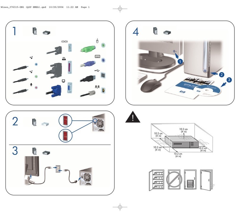
HP ProDesk 485 G1 Installation instructions
Other HP Desktop manuals
HP
HP Pavilion Slimline s3220 User manual
HP
HP Pavilion 21-a000 Specification sheet
HP
HP Visualize J2240 Quick start guide
HP
HP Net Vectra Product manual
HP
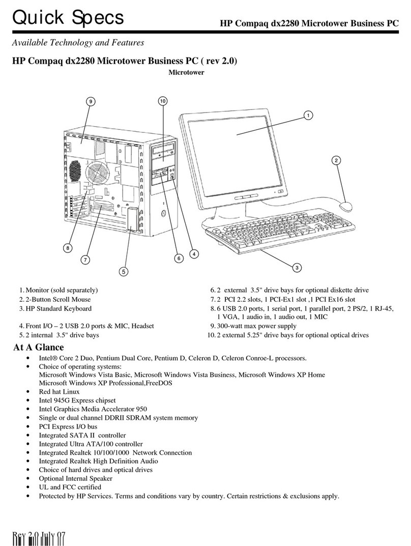
HP dx2280 - Microtower PC User instructions
HP
HP Vectra VE 5/xxx - 2 User manual
HP
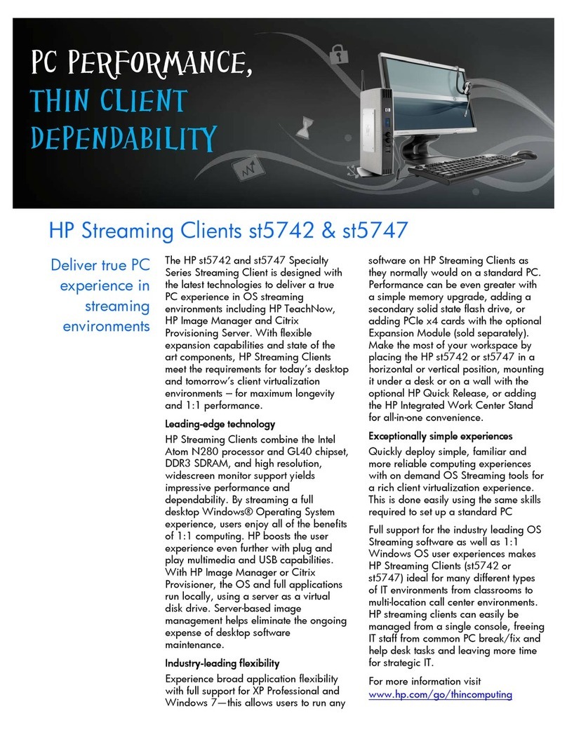
HP st5742 - Streaming Client User manual
HP
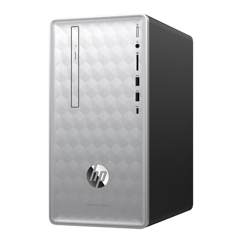
HP Pavilion 590 Installation instructions
HP
HP Pavilion MS210 User manual
HP
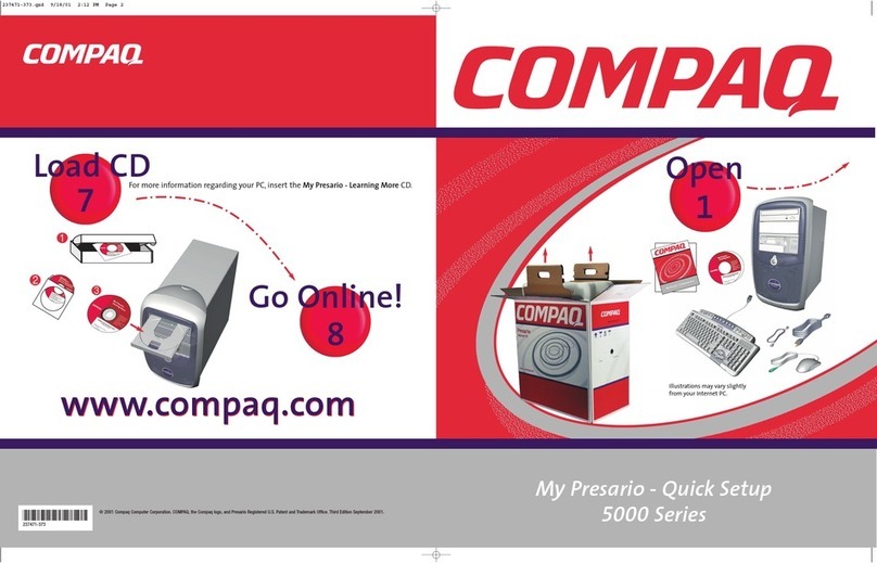
HP Compaq Presario Specification sheet
HP
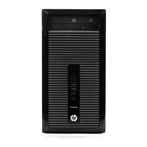
HP ProDesk 405 G1 Manual

HP
HP EliteDesk 880 G5 Manual
HP
HP ms6005 Operating and maintenance manual

HP
HP Vectra VL 6/xxx - 6 User manual
HP
HP dc5100 - Microtower PC User manual
HP
HP A1210n - Pavilion - 512 MB RAM User manual

HP
HP Xw4400 - Workstation - 2 GB RAM User instructions

HP
HP Compaq Presario User manual

HP
HP ProDesk 405 G2 User manual
HP
HP Pavilion t400 - Desktop PC Installation instructions

