manuals.online logo
Brands
  1. Home
  2. •
  3. Brands
  4. •
  5. HP
  6. •
  7. Desktop
  8. •
  9. HP Rp5000 - Point of Sale System Installation instructions

HP Rp5000 - Point of Sale System Installation instructions

HP-00007-01, Appendix 3 30-Jun-2005
HP Restricted
Page 1
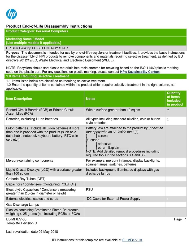
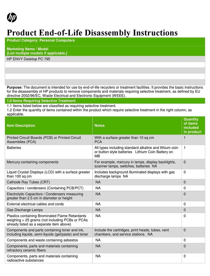
Appendix 3 Product End-of-Life Disassembly instructions
Product Identification:
Marketing Name / Model Description
RPOS/RP5000 Small Form Factor, ATX, Point-of-Sale
Purpose: The document is intended for use by end-of-life recyclers or treatment facilities. It provides the
basic instructions for the disassembly of HP products to remove components and materials requiring
selective treatment.
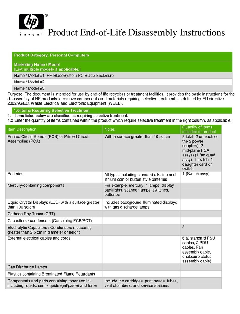
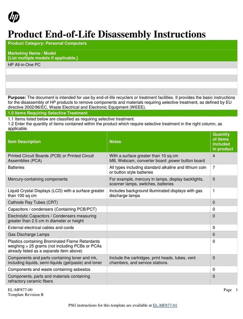
1.0 Items Requiring Selective Treatment
1.1 Items listed below are classified as requiring selective treatment.
1.2 Enter the quantity of items contained within the product which require selective treatment in
the right column, as applicable.
Item Description Notes Qty items in
product.
Printed Circuit Boards (PCB) or Printed
Circuit Assemblies (PCA)
With a surface greater than 10
square cm
4 PCS
- system bd
- pwr supply bd
- USB+Power bd
- riser card
Batteries All types including standard
alkaline and lithium coin or button
style batteries
1 PCS
Mercury containing components For example, mercury in lamps,
display backlights, scanner lamps,
switches, batteries
0
Liquid Crystal Displays (LCD) with a
surface greater than 100 square cm
Includes background illuminated
displays with gas discharge lamps
0
Cathode Ray Tubes (CRT) 0
Capacitors / condensers (Containing
PCB / PCT)
0
Electrolytic Capacitors / Condensers
greater than 2.5 cm in diameter or hght
0
External electrical cables and cords 0
Gas Discharge Lamps 0
Plastics containing Brominated Flame
Retardants
0
Components and parts containing toner
and ink, including liquids, semi-liquids
(gel/paste) and toner
Include the cartridges, print
heads, tubes, vent chambers, and
service stations.
0
Components & waste containing
asbestos
0
Components, parts and materials
containing refractory ceramic fibers
0
Components, parts and materials
containing radioactive substances
0
HP-00007-01, Appendix 3 30-Jun-2005
HP Restricted
Page 2
2.0 Tools Required
List the type and size of the tools that would typically be used to disassemble the product to a
point where components and materials requiring selective treatment can be removed.
Tool Description Tool Size (if applicable)
Torx Screw Driver
+Philips Screw Driver
3.0 Product Disassembly Process
3.1 List the basic steps that should typically be followed to remove components and materials
requiring selective treatment:
- RISER CARDS
- USB+POWER CARD
- SYSTEM BOARD
1 To remove the access panel (see Figure 1 below):
a) On the top of the computer, locate the cover latch. Pull up and hold the latch to release
the computer access panel.
b) Slide the computer access panel back about 0.5 inch (1.25 cm), and then lift the access
panel up and off the chassis.
2 To remove the front bezel (see Figure 2 & 3 below):
a) Depress the three plastic tabs on top of the bezel as indicated by the green arrows.
b) Pull the bezel away from the chassis.
3 Rotate the drive cage to the upright position (see Figure 4 below).
4 Unplug all cables from the system board.
5 Remove the riser card cage by grasping the green labels and pulling it straight upward
(see Figures 5 & 6 below).
6 Remove riser cards from the riser card cage using a torx screw driver.
7 To remove the USB+Power card from the AGP slot:
a) Release the slot cover retention latch located on the chassis wall (see Figure 7 below).
b) Remove any cables connected to the card.
c) Pull the retention arm away from the socket, and then carefully rock the card back and
forth until the connectors pull free from the socket (see Figure 8 below).
d) Lift the card straight up, then pull it in toward the center of the chassis to maneuver it
around the chassis frame (see Figure 9 below).
8 To release the system board tray (see Figure 10 below):
a) Depress the release mechanism as indicated by the green label, and then slide the
tray forward.
b) Lift the tray out of the unit.
9 Remove the system board from the system board tray using a torx screw driver.
HP-00007-01, Appendix 3 30-Jun-2005
HP Restricted
Page 3
POWER SUPPLY PCA
1 To remove the power supply from the chassis:
a) Remove the screw on the left side that secures the rear panel to the chassis
(see Figure 11 below).
b) Remove the two screws on the right side that secure the rear panel to the chassis and
to the power supply (see Figure 12 below).
c) Remove the rear panel from the baseplate (see Figure 13 below).
d) Slide the power supply toward the back chassis, and then remove it from the chassis
(see Figures 14 & 15 below).
2 Remove all screws from the power supply and remove the top and side panels
(see Figure 16 below).
3 Unplug all cables connected to the PCA inside of the power supply.
4 Remove the power supply PCA using a Philips screw driver (see Figures 17 & 18 below).
BATTERY
1 Locate the battery and battery holder on the system board.
2 To release the battery from the holder, squeeze the metal clamp that extends above one
edge of the battery (see Figure 19 below).
3 When the battery pops up, lift it out
HP-00007-01, Appendix 3 30-Jun-2005
HP Restricted
Page 4
3.2 ILLUSTRATIONS
FIGURE 1: Removing the access panel
FIGURE 2: Removing the front bezel
FIGURE 3: Front bezel removal tabs
FIGURE 4: Rotating the drive cage
FIGURE 5: Riser card cage
FIGURE 6: Removing the riser card cage
HP-00007-01, Appendix 3 30-Jun-2005
HP Restricted
Page 5
FIGURE 7: Releasing the slot cover retention latch
FIGURE 8: Loosening the USB+Power card
FIGURE 9: Removing the USB+Power card
FIGURE 10: System board tray/label
FIGURE 11: Rear panel screw – left side
FIGURE 12: Rear panel screws – right side
HP-00007-01, Appendix 3 30-Jun-2005
HP Restricted
Page 6
FIGURE 13: Rear panel removed
FIGURE 14: Removing the power supply
FIGURE 15: Power supply
FIGURE 16: Power supply with sides removed
Slide toward back of chassis
HP-00007-01, Appendix 3 30-Jun-2005
HP Restricted
Page 7
FIGURE 17: Power supply PCA screw locations
FIGURE 18: Power supply PCA screw locations
FIGURE 19: Removing the battery holder

Other manuals for Rp5000 - Point of Sale System

13

Other HP Desktop manuals

HP t630 Thin Client User manual

HP

HP t630 Thin Client User manual

HP A320m - Pavilion - 256 MB RAM User manual

HP

HP A320m - Pavilion - 256 MB RAM User manual

HP Compaq dx6100 Series Use and care manual

HP

HP Compaq dx6100 Series Use and care manual

HP c3700 - Workstation User manual

HP

HP c3700 - Workstation User manual

HP Pavilion a400 - Desktop PC Installation instructions
HP

HP Pavilion a400 - Desktop PC Installation instructions

HP XZ822UT#ABA User manual

HP

HP XZ822UT#ABA User manual

HP BladeSystem Blade Switch Assembly instructions

HP

HP BladeSystem Blade Switch Assembly instructions

HP Vectra XM5 4 User manual

HP

HP Vectra XM5 4 User manual

HP Net Vectra n30 Manual

HP

HP Net Vectra n30 Manual

HP Elite Slice G2 Manual

HP

HP Elite Slice G2 Manual

HP 742n - Pavilion - 512 MB RAM User manual

HP

HP 742n - Pavilion - 512 MB RAM User manual

HP Media Center Instruction Manual

HP

HP Media Center Instruction Manual

HP Pavilion Elite e9260f User manual

HP

HP Pavilion Elite e9260f User manual

HP Presario All-in-One CQ1-1000 - Desktop PC Use and maintenance manual

HP

HP Presario All-in-One CQ1-1000 - Desktop PC Use and maintenance manual

HP Compaq dx2810 Microtower User manual

HP

HP Compaq dx2810 Microtower User manual

HP Compaq Presario Instruction Manual

HP

HP Compaq Presario Instruction Manual

HP Compaq Presario Manual

HP

HP Compaq Presario Manual

HP Pavilion a200 - Desktop PC Manual

HP

HP Pavilion a200 - Desktop PC Manual

HP Presario CQ5700 - Desktop PC Use and maintenance manual

HP

HP Presario CQ5700 - Desktop PC Use and maintenance manual

HP 8100 - Elite Convertible Minitower PC User manual

HP

HP 8100 - Elite Convertible Minitower PC User manual

HP Media Center m1000 - Desktop PC Quick guide

HP

HP Media Center m1000 - Desktop PC Quick guide

HP Kayak XA-s 02xx Manual

HP

HP Kayak XA-s 02xx Manual

HP Compaq Presario Manual

HP

HP Compaq Presario Manual

HP Compaq dx6120 MT Manual

HP

HP Compaq dx6120 MT Manual

Popular Desktop manuals by other brands

Contec IPC-BX/M560 user manual

Contec

Contec IPC-BX/M560 user manual

PCchips BKi810 manual

PCchips

PCchips BKi810 manual

A1 Touch AOD 260 user manual

A1 Touch

A1 Touch AOD 260 user manual

Data General AViiON Series Customer Documentation

Data General

Data General AViiON Series Customer Documentation

Sealey AP1905A instructions

Sealey

Sealey AP1905A instructions

Gateway FX530 reference guide

Gateway

Gateway FX530 reference guide

Sony VGN-P21S/W user guide

Sony

Sony VGN-P21S/W user guide

Winmate Tandy Sensation manual

Winmate

Winmate Tandy Sensation manual

Quanmax QutePC-2000 user guide

Quanmax

Quanmax QutePC-2000 user guide

Rikomagic MK802 III user guide

Rikomagic

Rikomagic MK802 III user guide

Dell Precision ND218 Quick reference guide

Dell

Dell Precision ND218 Quick reference guide

IBM PC 300GL Types 6275 Software guide

IBM

IBM PC 300GL Types 6275 Software guide

Acer Veriton 9100 Service guide

Acer

Acer Veriton 9100 Service guide

Dell Inspiron 3470 Setup and Speci?cations

Dell

Dell Inspiron 3470 Setup and Speci?cations

Quanmax QBOX-1010 user guide

Quanmax

Quanmax QBOX-1010 user guide

AOpen WARM TOUCH WT22M-RH Technology manual

AOpen

AOpen WARM TOUCH WT22M-RH Technology manual

Moxa Technologies MPC-2120 Series Hardware user manual

Moxa Technologies

Moxa Technologies MPC-2120 Series Hardware user manual

Asus B5081ZD user manual

Asus

Asus B5081ZD user manual

manuals.online logo
manuals.online logoBrands
  • About & Mission
  • Contact us
  • Privacy Policy
  • Terms and Conditions

Copyright 2025 Manuals.Online. All Rights Reserved.