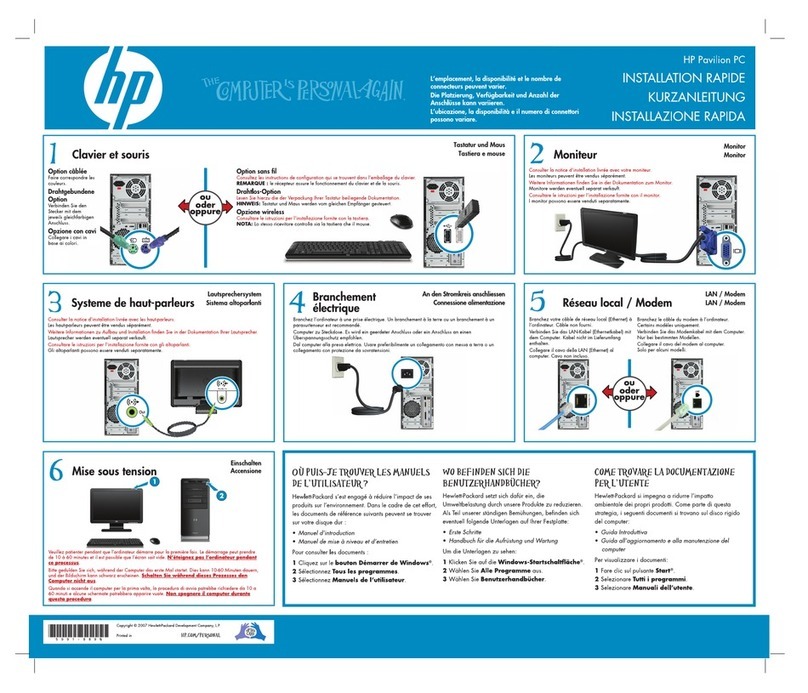
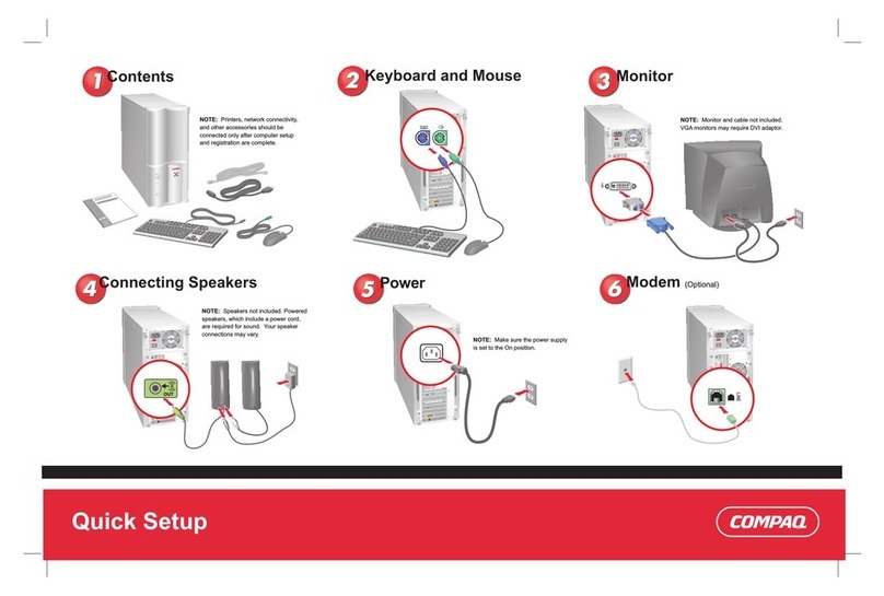
connecting the system
A label on the back of the system identifies the ports. Connect all cables and cords before
you plug the power cord into the outlet. The connectors are shaped to go in one way only.
NOTE Systems with video cards supporting multiple heads have more than one
monitor connector.
configuring the system
1Power on the system.
aTurn on the monitor.
bPress the power button on the front panel.
cEnter the password if required. (Password is required if previously set in EFI.)
2Initialize the software.
• If you purchased a system with the OS pre-installed, the initialization process begins
when you start the workstation for the first time. This process:
— Displays the license agreement.
— Asks questions about the system.
• If you purchased a system and the OS is not pre-installed, install the OS now.
— HP-UX: Follow the instructions on the HP-UX CD envelope to install your OS.
— Linux: Follow the instructions on the Linux OS CD envelope to install your OS.
(Windows is always pre-installed.)
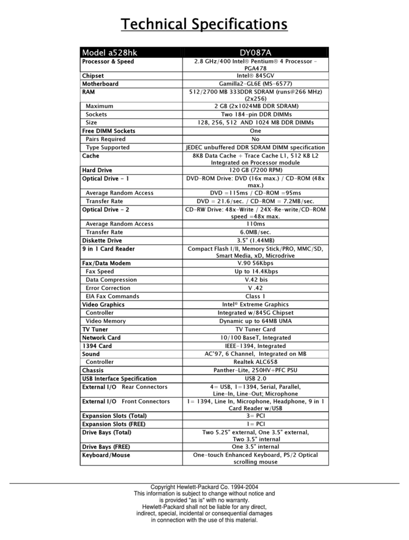
3Use the following tools to configure the system. For instructions, refer to the HP zx2000
Technical Reference Guide.
• Extensible Firmware Interface (EFI)
• Baseboard Management Controller (BMC)
4Install software and drivers for peripherals.
• Go to “Software and Drivers” at www.hp.com/go/bizsupport.
removing and replacing covers
NOTE Rack-mounted systems do not have plastic side covers.
CAUTION The zx2000 system depends on the access panels for proper cooling of internal
components. Operating the system with the side cover removed can cause the
system to quickly overheat.
WARNING For hardware installation procedures, you must power off the system and unplug
the power cord from the outlet.
location of internal components
installing components
For detailed instructions, refer to the HP zx2000 Technical Reference Guide.
NOTE To maintain FCC/EMI (Electromagnetic Interference) compliance, replace all covers
and make sure all screws are properly seated after you replace components.
memory
The order in which you load memory is important. Refer to the chart below.
NOTE Memory DIMMs must be loaded as matched pairs.
CAUTION If you do not unplug the power cord while removing and installing memory, your
memory modules may be damaged. Make sure the power cord is disconnected and
the power supply LED is off before adding or removing DIMMs.
drives
To remove or install hard drives, you must first raise the hard drive cage.
• To raise the hard drive cage, remove the screws that hold the cage in place for shipping.
Replacing these screws is not necessary.
graphics and accessory cards
The graphics and accessory cards in the system are behind the hard drive cage and AGP
retainer arm. To remove or install graphics and accessory cards, you must first raise the hard
drive cage and remove the AGP retainer arm from the system.
• To remove the AGP retainer arm, remove the screws that hold the hard drive cage and
retainer arm in place for shipping. Replacing these screws is not necessary.
1PCI and AGP slots
2PCI/AGP retainer arm
3memory
4power supply
5hard drive cage
6optical drives
7shipping screws
8fans
9front-access USB
Location of power supply (reference point)
Loading Order Memory DIMM Slots
1st DIMM 0A
2nd DIMM 1A
1st DIMM 0B
2nd DIMM 1B
