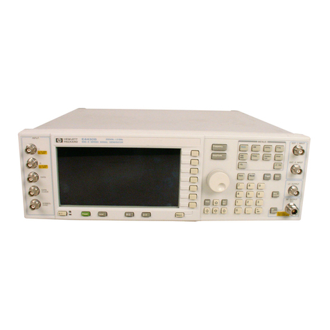
HP 5065A Service manual

OPERATINGANDSERVICEMANUAL
5065A
RUBIDIUMVAPOR
FREQUENCYSTANDARD
WaHWBMfC-
>"^"io
%* #
(a)~*
ReproducedwithPermission.courtesyofAgilentTechnologies,Inc.
PDFproducedISSeptember2009byBrianKirby- KD4FM
NOTFORRESALE aHEWLETT
PACKARD
5

SAFETY
This
product
has
been designed and testedaccording to International
Safety
Requirements.
To
ensure
safeoperation and to keep the product safe,the information, cautions, and warnings in this manual
must be heeded. Refer to Section I for general safety considerations applicable to this product.
CERTIFICATION
Hewlett-Packard Company certifies that this product met its published specifications at the time of
shipment from the factory. Hewlett-Packard further certifies that its calibration measurements are
traceable to the United
States
National Bureau of
Standards,
to the extent allowed by the Bureau's
calibration facility, and to the calibration facilities of other International Standards Organization
members.
WARRANTY
ThisHewlett-Packardproduct
is
warrantedagainstdefectsinmaterialandworkmanshipfor
a
periodof
oneyearfromdateofshipment,exceptthatinthe
case
ofcertaincomponentslistedinTable1-3ofthis
manual,
thewarrantyshallbeforthespecifiedperiod.Duringthewarrantyperiod,Hewlett-Packard
Company
will,
atitsoption,eitherrepairorreplaceproductswhichprovetobedefective.
Forwarrantyserviceorrepair,thisproductmustbereturnedtoa servicefacilitydesignatedbyHP.
However,warrantyserviceforproductsinstalledbyHPandcertainotherproductsdesignatedbyHP
willbeperformedatBuyer'sfacilityatnochargewithintheHPservicetravelarea.OutsideHPservice
travelareas,warrantyservicewillbeperformedatBuyer'sfacilityonlyuponHP'sprioragreementand
BuyershallpayHP'sroundtriptravelexpenses.
ForproductsreturnedtoHPforwarrantyservice,Buyershallprepay shippingchargestoHPandHP
shallpayshippingchargestoreturntheproducttoBuyer.However,Buyershallpayallshipping
charges,duties,andtaxesforproductsreturnedtoHPfromanothercountry.
LIMITATIONOFWARRANTY
Theforegoingwarrantyshallnotapplytodefectsresultingfromimproperorinadequatemaintenance
byBuyer,Buyer-suppliedsoftwareorinterfacing,unauthorizedmodificationormisuse,operation
outsideoftheenvironmentalspecificationsfortheproduct,orimpropersitepreparationor
maintenance.
NOOTHERWARRANTYISEXPRESSEDORIMPLIED.HPSPECIFICALLYDISCLAIMSTHEIMPLIED
WARRANTIESOFMERCHANTABILITYANDFITNESSFORA PARTICULARPURPOSE.
EXCLUSIVEREMEDIES
THEREMEDIESPROVIDEDHEREINAREBUYER'SSOLEANDEXCLUSIVEREMEDIES.HPSHALLNOT
BELIABLEFORANYDIRECT,INDIRECT,SPECIAL,INCIDENTAL,ORCONSEQUENTIALDAMAGES,
WHETHERBASEDONCONTRACT,TORT,ORANYOTHERLEGALTHEORY.
ASSISTANCE
Product maintenance agreements and other customer assistance agreements are available for
Hewlett-Packard products.
For any
assistance,
contact your nearest Hewlett-Packard
Sales
and Service Office. Addresses are
provided at the back of this manual.

RUBIDIUMVAPORFREQUENCYSTANDARD
5065A
SERIALPREFIX:1908A
ThismanualappliesdirectlytoHPModel5065ARubidium
VaporFrequencyStandardshavingserialprefix1908A.
OLDERINSTRUMENTS
Changesrequiredtobackdatethismanualforolderin-
strumentsareinSectionVII.
OPTIONS
ForinstrumentshavingOptions
001,
002,or003,referto
SectionsIIIthroughVII.
CopyrightHEWLETT-PACKARD1979
5301STEVENSCREEKBLVD.,SANTACLARA,CALIF.95050
ManualPartNo.05065-9041
MicrofichePartNo.05065-9042Printed:NOV1979
What
HEWLETT
mllHM
PACKARD

Model5065A
ManualContents
MANUALCONTENTS
Thismanualissuppliedtohelpyoumakebestuseof
yourinstrument.Themanualcoverseightsectionsof
informationasfollows:
SectionI isanintroductiontotheInstrument.Elec-
tricalspecificationsandaccessoriesinformationis
given.
SectionIIcoversinspections,power,mounting,pack-
ing,
shipping,andconnection.
SectionIIIoutlinesoperatingprocedures.
SectionIVdiscussestechnicaloperations.
SectionV contrainsdisassemblyandrepairprocedures
andanin-cabinetperformancecheck.
SectionVIlistsreplaceableparts.
SectionVIIgivesoptionsandmanualchanges
information.
SectionVIIIcontainscircuitdiagrams,component
locatorsandwaveforms.Includedareadjustment
proceduresandtroubleshootinginformation.
HOWTOORDER
Toorderanoperatingandservicemanual,contactthe
nearestHewlett-PackardSalesandServiceOffice.
Givecompletemodel,name,andnine-digitserial
number.Theserialnumberplateisontherearpanel.
CommentsonthismanualarewelcomeatanySales
andServiceOffice.

Model5065A
TableofContents
TABLEOFCONTENTS
SectionPage
IGENERALINFORMATION1-1
1
-1.
Introduction1-1
1-2.Description1-1
1-5.Options1-1
1-6.CircuitChecksandOutputs1-1
1-8.Terminology1-1
1-10.Specifications1-1
1-13.InstrumentIdentification1-1
IIINSTALLATION2-1
2-1.
UnpackingandInspection2-1
2-3.
StorageandShipment2-1
2-4.
Environment2-1
2-6.
ExtendedStorage2-1
2-8.RVFRStorageProcedure2-1
2-10.Packaging2-1
2-14.ElectricalConnections2-2
2-15.PowerConnection2-2
2-18.MatingConnectors2-2
2-20.OperationasBenchorRackInstrument2-3
2-22.
InstallationLocation2-3
IIIOPERATION3-1
3-1.
Introduction3-1
3-3.Options001and002(Option003= 001and002)3-1
3-5.OperatingProcedure3-1
3-6.General3-1
3-8.Turn-OnProcedure(seeFigure3-2)3-1
3-9.Turn-OnAfterLongStorage3-1
3-10.FrequencyOffsetandCalibration3-2
3-18.FrequencyComparisonUsingK34-59991ALinearPhaseDetector3-5
3-19.OperationwithTimeStandardOption001(or003)3-9
3-22.SettingtheClockPhasetoanExternalClock3-9
3-24.AutomaticSynchronization3-9
3-26.ManualSynchronization3-9
3-28.SettingtheClock3-9
3-29.OperationwithStandbyPowerSupplyOption0023-11
IVTHEORYOFOPERATION4-1
4-1.
Theory4-1
4-2.
General4-1
4-15.
Option001,TimeStandard4-2
4-20.
Option002,StandbyPowerSupply4-3
VMAINTENANCE5-1
5-1.
Introduction5-1
5-5.InstrumentAccess5-1
5-7.PeriodicMaintenance5-1
5-8.InstrumentTroubleshooting5-6
5-9.Introduction5-6
5-15.FaultFinding5-7
5-19.LoopAlignmentProcedure5-12
5-20.Introduction5-12
5-22.+20VoltAdjustment(A15PowerSupplyand
RegulatorAssembly)5-12
5-24.A10FrequencyAdjustment5-12
5-25.RFAlignment5-13
5-26.Signal-to-NoiseRatio5-14
5-27.ModulationFrequencyAdjustment5-14
5-28.PhaseAdjustmentRecheck5-14
IV

Model5065A
TableofContents,ListofFigures
TABLEOFCONTENTS(Continued)
SectionPage
5-29.PhaseDetectorandIntegratorZeroAdjustment5-15
5-30.LoopGainAdjustment5-15
5-31.
LoopAssembly(A14)Alignment5-15
5-32.Option002,StandbyPowerSupplyMaintenance5-16
5-37. BatteryRemovalandReplacement5-16
5-38.ClockDisplayAssemblyA195-16
VIREPLACEABLEPARTS6-1
6-1.
Introduction6-1
6-4.OrderingInformation6-1
VIIMANUALCHANGESANDOPTIONS7-1
7-1.
ManualChanges7-1
7-3.NewerInstruments7-1
7-5.OlderInstruments7-1
7-7.Options7-1
7-9.Option001TimeStandard7-1
VIIICIRCUITDIAGRAMS8-1
8-1.
General8-1
LISTOFFIGURES
FigurePage
1
-1.
Model5065AandAccessories1-0
2-1.
ElectricalHookupforRVFRStorage2-2
2-2.
ConversionforRackMounting2-3
3-1.
RVFRPumping3-2
3-2.Turn-OnProcedure3-3
3-3.MagneticFieldControl3-5
3-4.ErrorMeasurement3-5
3-5.EquipmentSetupforCalibratingPhaseMeasurementSystem3-7
3-6.EquipmentSetupforFrequencyDifferenceMeasurement3-8
3-7.InternalMeasurementwithAutomaticSynchronization3-12
3-8.InternalMeasurementwithManualSynchronization3-12
3-9.FrontPanelControls3-13
3-10.RearPanelOperatingControls3-14
3-11.
TopOperatingControls3-15
4-1.
RubidiumAbsorptionPlot4-1
4-2.
Rb87AbsorptionCellOutput4-2
4-3.
RVFRAssemblyBlockDiagram4-3
5-1.
A8TP3Waveformat200x 10-10andPhaseMisadjusted5-2
5-2.A8TP3Waveformat200X 10-10andPhaseCorrect5-2
5-3.HarmonicandNon-HarmonicDistortionTestSetup5-3
5-4.EquipmentSetupforSynchronizationandDelayChecks5-4
5-5.5 MHzOutputStabilityTestSetup5-5
5-6.5065ASimplifiedBlockDiagram5-7
5-7.MeterResponseinERRORPosition5-10
5-8.WaveformatA8TP3withSeverePhaseShift5-12
5-9.R.F.AlignmentSetup5-13
5-10.OscilloscopeIndicationatResonancewithA8R43(ModulatingPhase
Adjustment)CorrectlyAdjusted5-13
5-11.
Signal-to-NoiseTestSetup5-14
6-1.
ModularCabinetParts6-2
v

Model5065A
ListofFigures
LISTOFFIGURES(Continued)
FigurePage
7-1.
BatteryChargerAssemblyA2Option0027-3
7-2.A2BatteryChargerAssembly7-3
7-3.100kHzRegenerativeDivider7-8
7-4.A4100kHzDivider7-11
7-5.A4100kHzFrequencyDividerAssembly7-11
7-6.A1Waveforms7-21
7-7.SynthesizerAssemblyA1BlockDiagram7-21
7-8.A1SynthesizerAssembly7-23
7-9.PartofA1SynthesizerAssembly7-23
7-10.A1Waveforms7-25
7-11.
SynthesizerA1Phase-LockedOscillatorSection7-25
7-12-A7ACAmplifierComponentLocator7-35
7-13.A7ACAmplifierSchematicDiagram7-35
7-14.TopOperatingControls7-37
7-15.A5DigitalDividerAssembly(Option001)7-39
7-16.A16DigitalDividerPowerSupplyAssembly7-41
7-17.A19LEDDigitalClockAssembly7-51
7-18.TopOperatingControls7-53
7-19.A5DigitalDividerAssembly7-55
7-20.A16DigitalDividerPowerSupplyAssembly7-57
8-1.
SchematicDiagramNotes8-2
8-2.BlockDiagram8-3
8-3.FrontandRearPanelandTopInternalViews8-4
8-4.WiringDiagram(Sheet1 of3)8-5
8-5.BottomInternalView8-6
8-6.WiringDiagram(Sheet2 of3)8-7
8-7.WiringDiagram(Sheet3 of3)8-9
8-8.SynthesizerAssemblyA1BlockDiagramDigitalSection8-11
8-9.SynthesizerAssemblyA1DigitalSection(Sheet1 of2)8-17
8-9.SynthesizerAssemblyA1Phase-LockedOscillatorSection(Sheet2 of2)8-19
8-10.A2BatteryChargeAssembly(Option002and003)8-21
8-11.
A3MultiplierAssembly8-25
8-12.A4100kHzFrequencyDivider8-27
8-13.A5DigitalDividerAssembly(Option001)(Sheet1 of3)8-33
8-14.A5A2MasterClockBoard(Option001)(Sheet2 of3)8-35
8-15.A5A3PresetClockBoard(Option001)(Sheet3 of3)8-37
8-16.A61 MHzFrequencyDividerAssembly8-41
8-17.A7ACAmplifierAssembly8-43
8-18.A8PhaseDetectorAssembly8-47
8-19,A9IntegratorAssembly8-49
8-20.A10OscillatorAssemblyBlockDiagram8-53
8-21.
A11RVFRTemperatureControllerAssembly8-55
8-22.A12RVFRAssemblyandBufferA13AmplifierAssembly8-59
8-23.A14LogicAssembly8-63
8-24.A15PowerSupplyandRegulatorAssembly8-65
8-25.A16DigitalDividerPowerSupplyAssembly8-67
8-26.A19Series1740DigitalClockSchematicDiagram8-71
VI

Model5065A
ListofTables
LISTOFTABLES
rablePage
1-1.
EquipmentSupplied1-2
1
-2.
AccessoriesAvailable1-2
1-3.Specifications1-3
2-1.
115/230VoltConversion2-2
2-2.
MatingConnectors2-3
3-1.
OperatingChecks3-1
3-2.FrontPanelLampIndications3-4
3-3.FrequencyOffsetChangeInstructions3-6
3-4.TypicalFrequencyOffsetChange,Sample(Insufficient
MAGNETICFIELDControl)3-7
3-5.TypicalFrequencyOffsetChange,0X10-10Offsetto-300x10-103-8
3-6.OffsetFrequencySettings3-10
3-7.SynthesizerSettingvs.FrequencyOffset3-11
3-8.RecommendedTestEquipment3-11
4-1.
LogicSignals4-3
5-1.
AssemblyDesignations5-1
5-2.In-CabinetPerformanceCheck5-2
5-3.CircuitChecks5-8
5-4.SignalChecks5-10
5-5.RecommendedTestEquipment5-11
5-6.A5Troubleshooting5-17
6-1.
TableofAbbreviations6-1
6-2.ReplaceableParts6-3
6-3.Option002and003ReplaceableParts6-21
6-4.Option001ReplaceableParts6-23
6-5.Options
001,
003OnlyReplaceableParts6-27
6-6.ManufacturersCodeList6-31
7-1.
ManualChanges7-1
7-2.BatteryChargerReplaceableParts7-5
7-3.A4100kHzDividerReplaceableParts7-13
7-4.A1SynthesizerAssemblyReplaceableParts7-17
7-5.A1Troubleshooting7-26
7-6.A1Troubleshooting7-27
7-7.A1Troubleshooting
7-7.A1Troubleshooting7-28
7-8.A1Troubleshooting7-29
7-9.A7ACAmplifierAssemblyReplaceableParts7-32
7-10.A16ResistorPartsList7-38
7-11.
A16ResistorPartsList7-52
7-12.A5A4PartsList7-58
vii

Model5065A
CircuitDiagrams,Theory,andMaintenance
Figure
1-1.
Model5065AandAccessories
ShownwithOption003(001+ 002= 003)
ACPOWERCORD RACKMOUNTKIT
" i
ACCESSORYKIT
£T
1-0

Model5065A
CircuitDiagrams,Theory,andMaintenance
SECTIONI
GENERALINFORMATION
1-1.
INTRODUCTION1-8.TERMINOLOGY
1-2.Description
1-3.TheHewlett-PackardModel5065ARubidium
VaporFrequencyStandardisa compact,self-contained
secondaryfrequencystandardwhichusesanoptically-
pumpedRubidiumvaporcellasthereferenceelement.
A5 MHzoscillatorisstabilizedagainsta natural
atomicresonance,thehyperfinetransitionof
Rubidium87.Thistechniqueproducesa long-term
stabilityofbetterthan1 x 10-"permonthwith
excellentshort-termstabilitywhichisconservatively
ratedatlessthan5 x 10-12rmsaveragedovera one-
secondperiod.Outputfrequenciesare5 MHz,1 MHz,
and100kHz.
1-4.FrequencysettingforanyoffsetoftheUTCtime
referenceisaccomplishedbychangingthemicrowave
excitationfrequencyandthemagneticfieldapplied
toanRb67vapor
cell.
Thumbwheelswitchcontrol
(ofa digitalfrequencysynthesizer)providesapproxi-
matestepadjustmentofthemicrowaveexcitation
fre-
quencywitha rangeof1000partsin1010.Inaddition,
thefront-panelMAGNETICFIELDcontrolprovides
forexactadjustmentoftheRb87hyperfinetransition
witha resolutionof2 partsin1012.
1-5.Options
a.A digitalclock,Option
001,
providesa clockdis-
playanda onepulsepersecond
(1
PPS)electricaloutput.
Theclockpulsemayberetardedupto
1-second
inincre-
mentsassmallas1-microsecondandaslargeas0.1-
second.
Inaddition,a separatecontrolprovidescontin-
uousadjustmentofclock-pulsedelayfrom0-to1-
microsecond.
b.Standbybattery,Option002,providesa 10-
minuteminimumpowersource(at25°C)intheevent
ofexternalacpowerfailure.A front-panellamp
flasheswhenacpowerisinterruptedandlights
con-
tinuouslyduringfastcharge.Chargerateis
con-
trolledbya 3-positionfront-panelswitch;FAST,
CHARGE-FLOAT,RESET.
1-6.CircuitChecksandOutputs
1-7.TheCIRCUITCHECKswitchandmeterprovide
continuousmonitoringofoutputsandothersignals.
TheCONTINUOUSOPERATIONlampgivesan
indi-
cationofcorrectoperation.The5 MHz,1 MHz,and
100kHzoutputlevelsareatleastt voltrmswhen
properlyterminatedwith50ohms.
1-9.Thedefinitionsofthefollowingtermsapplyto
thesetermsasusedthroughoutthismanual.
a.ATOMICTIME.Timescalebasedonthe
hyperfineresonanceofCesium133.
b.UNIVERSALTIME(UT2).Timescalebased
ontheearth'srotationaboutitsaxiswithcorrection
forangularpositionandseasonalvariations;proceeds
ata rateslightlyslowerthanAtomictime.
c.UNIVERSALTIME(COORDINATED)(UTC).A
piecewiseuniformscalewhichapproximatesUT2to
0.1-secondbystepadjustmentsinphaseasannounced
bytheBureauInternationalde
I'Heure
inParis.
d.
HYPERFINERESONANCEOFRb87.Hyper-
fineresonantfrequencyarisingfromthedifference
inenergybetweentheupperandlowergroundstates
ofRb87.
e.RVFR(RubidiumVaporFrequencyReference).
TheassemblywhichhousestheRb87lamp,filter
cell,
theRb87absorption
cell,
andtheharmonicgenerator/
mixerdiode.
1-10.SPECIFICATIONS
1-11.
Table1-3liststhetechnicalspecificationsfor
theModel5065A.
1-12.Table1-1listsequipmentsuppliedandTable
1-2listsaccessoriesavailablefortheModel5065A.
1-13.INSTRUMENTIDENTIFICATION
1-14.Hewlett-Packardusesa two-sectionnine-digit
serialnumber(0000A00000)mountedontherear-
paneltoidentifythisinstrument.Thefirstfourdigits
aretheserialprefixandthelastfivedigitsrefertothe
specificinstrument.Iftheserialprefixonyourinstru-
mentdiffersfromthatlistedonthetitlepageofthis
manual,
differencesexistbetweenthemanualand
yourinstrument.Lowerserialprefixesaredocumented
inSectionVIIandhigherserialprefixesarecovered
bya manualchangesheetincludedwiththemanual.
IfthissheetismissingcontactthenearestHewlett-
PackardSalesandServiceoffice(listsareprovided
attherearofthismanual). 1-1

Model5065A
CircuitDiagrams,Theory,andMaintenance
Table1-1.EquipmentSuppliedTable1-2.AccessoriesAvailable
Equipment
ACPowerCable
AccessoryKit
includes:
Adapter
Connector
Screwdriver
CableAssembly
Test
BoardExtender
BoardExtender
BoardExtender
Description
3-Conductor
with
groundpin
Micon,
male-to-
male
Plug,
female
Ceramic
MicontoBNC
15pin
15pin,extrawide
12pin
HPPartNo.
05061-6091
05065-6066
1250-0813
1251-0126
8710-0033
05060-6116
05065-6064
05065-6065
05061-6073
Accessory
StandbyPower
Supply
Cable
ExtensionSlides
andRack
StandbyPower
Supply
RackMountKit
Description
24Vdc,
2-ampere
supplywith18
ampere-hours
standbybatteries
Connects5065A
to5085Adc
output
Permitssliding
instrumentout
andtiltingfrom
rack-mounted
position
24Vdc,
2-ampere
supplywith12
ampere-hours
sealedstandby
batteriesfor
flyingclock
experiments.
Operateson6,
12,
and24Vdc,
115Vac/230Vac,
±10%,
48to
440Hz.
Provides
con-
versionfrom
benchtorack
model
HPPartNo.
Model5085A
103A-16A
1490-0718
1490-0721
K02-5060A
5060-8740
1-2

Model5065A
CircuitDiagrams,Theory,andMaintenance
Table1-3.Specifications
5065A
FrequencyStability:
Longterm:
±1
x 10-"permonth(maximum
limitofdriftrate).
Shortterm*:for5 MHzoutput.
FractionalFrequencyFluctuationsAvg.Time(T)
<7.5x10-101ms
<1.5x10-1010ms
<1.5x10"110.1s
<5x10~121s
<1.6x10"1210s
<5x10~13100s
<5x10-131000s
CalibrationAccuracy:Setat
factoryto
±1
x 10""ofspecifiedtimescale.
Settabillty:±2x10-12.
Time
Scale:
SetatfactorytoUTCunlessspecified
differently.
Tunabllity:CoarseFrequencySynthesizerAdjust-
ment:Range:1000x10"10
Resolution:<2x 10⁻⁹,thumbwheeladjust.
FineFrequencyMagneticFieldAdjustment:
Range:2x10"9Resolution:2x10"12
Warm-up:Within
1
x
10-™
in
1
hourand5 x 10-"
in4 hoursoffinalfrequencyafter24hours"off"
timeat25°C.Unitstypicallywarm-uptobetter
than+2partsin10"offactorycalibrated
frequency.
'DEFINITIONOFTERMS
Short-TermStability:
SeeStatisticsofAtomicFrequencyStandardsby
DavidW.Allen,ProceedingsofIEEE,Feb.1966,
p.
221,
andHPApplicationNote116formeasure-
mentdetails.
Settablllty:
Thedegreetowhichanoscillatormaybeadjusted
tocorrespondwitha reference.Thisisalso
termedcalibration.
OUTPUTS:
Frequencies:5 MHz,
1
MHz,100kHz.
Voltages
Levels:
>1
V rmsinto50ohmsat5 MHz,
1MHz,100kHz.
Connectors:BNCFrontandRearfor5 MHz,
1MHz,100kHz.
HarmonicDistortion:(5MHz,
1
MHz,100kHz)
Downmorethan40dBfromratedoutput.
NonharmonicallyRelatedOutput:(5MHz,
1
MHz,
100kHz)Downmorethan80dBfromratedoutput.
Signai-to-Noise
Ratio:
For
1
and5 MHz,>87dB
atratedoutput(ina30kHznoisebw).
ENVIRONMENTAL:
Temperature,Operating:0°to50°C.Frequency
changeis<±4x 10"fromfrequencyreferenceat
at25°C.
Temperature,Nonoperating:-40°to+75°C.
(WithOptionsto50°C.)
ProductionUnitsHavePassedTypeTestasFollows:
HUMIDITY:0 to95%relativehumidity.
VIBRATION:
MIL-STD-167andMIL-E-5400,
CURVEI,withisolators.
SHOCK:MIL-T-21200,andMIL-E-5400(30G's).
ELECTROMAGNETICCOMPATIBILITY(EMC):
MIL-l-6181D andMIL-STD-461,ClassA.
ALTITUDE:Frequencychangeis>5x 10""from0
to40,000ft.
FREQUENCYSTABILITYDUETO:
MagneticFields:<5x10H2for
1
gaussdcchange
or
1
gausspeakac,60
+10%
Hzand400+10%Hz.
LineVoltage:<4x10H2overspecifiedinputrange.
MATINGCONNECTORS:
EXTDCinput:HP1251-0126(5-contact),Cannon
MS3106E-14S-5S (SeriesME)furnished.
POWER:115or230Vac
±10%,
50to400Hz,or
23to30Vdc.
Approx.powerrequired:
24Vdc115Vac
WithoutOptions
Option
001
(Add)
Option002(Add)
Option003(Add)
35W
7.5W
0W
7.5W
49W
10W
6W
16W
WEIGHT:Net,34lb(15,4kg).Shipping,
51
lb
(23,5kg).Option
001,
add2 lb(0,9kg).Option
002,
add3.5lb(1,6kg).
WARRANTY:
1
year,
except3 yearsforRVFR.
1-3

Model5065A
CircuitDiagrams,Theory,andMaintenance
Table1-3.Specifications(Continued)
OPTION
001
TIMESTANDARD
CLOCKPULSE:
Rate:
1pulseper
second.
RiseTlme:<50ns.
FallTime:<1
MS.
Amplitude:+10Vpeak±10%
Jitter:
5 nsrmsareWidth:20/ismin.Allspecs
with50n
load.
Output:Front-panelBNC.
SYNCHRONIZATION:Automaticto
10±1MS,
delayed
fromreferenceinputpulse(rearBNC).Manual
adj.
to+50ns.Referencepulsemustbe>+5v with
arisetime<50nsandwidth>0.5^is.
CLOCKMOVEMENT:24-hourLEDDigitalClock.
OPTION002STANDBYPOWERSUPPLY
CAPACITY:10-minuteminimumat25°Cafterfull
charge
(incl.
Option001).
CHARGECONTROL:Frontpanel,FastCharge-
Float-Resetswitch.
INDICATOR:A front-panellightflasheswhenac
powerisinterruptedandbatteryisbeingused.
Acontinuouslightindicatesafastchargecondition.
OPTION003
CombinesOptions
001
and002
PERFORMANCEOFQUARTZOSCILLATORONLY
(RubidiumControlLoopOpen)
AGINGRATE:<±5x 10⁻¹⁰per24hours.
FREQUENCYADJUSTMENTS:
FineAdjustment:5 x10srange,withdialreadings
ofpartsin1010.
CoarseAdjustment:1partin106,screwdriver
adjustmentatfrontpanel.
STABILITY:
Asa FunctionofAmbientTemperature:Fre-
quencychangeislessthatn2.5x
10"9
totalfrom
0°to+50°C.
Asa FunctionofLoad:±2x
10~11
fromopen
circuittoshort,50f2R,L,orC loadchange.
Asa FunctionofSupply
Voltage:
±5x
10'11
for
23to30Vdcfrom26Vdcreference,orfor
115/230Vac±10%.
DIMENSIONS:
DIMENSIONSININCHESAND(MILLIMETERS]
)EIARACKHEIGHT(INCLUDINGFILLERSTfllPl
FORCABINETHEIGHT!INCLUDINGFEET)ADO
j|
(8)TO
EIARACKHEIGHT
RAPTONRECESS
1-4

Model5065A
CircuitDiagrams,Theory,andMaintenance
SECTIONII
INSTALLATION
2-1.
UNPACKINGANDINSPECTION
2-2.
Iftheshippingcartonisdamaged,askthatthecar-
rier'sagentbepresentwhentheinstrumentisunpacked.
Inspectinstrumentfordamage(scratches,dents,broken
knobs,etc.).IfinstrumentisdamagedorfailsPerform-
anceCheck,notifythecarrierandthenearestHewlett-
PackardSalesandServiceofficeimmediately(Salesand
ServiceOfficeslistedinsidebackcover).Retaintheship-
pingcartonandthepaddingmaterialforthecarrier's
inspection.
Theofficewillarrangeforrepairorreplace-
mentwithoutwaitingfortheclaimagainstthecarrierto
besettled.
2-3.
STORAGEANDSHIPMENT
2-4.Environment
2-5.Temperaturesduringstorageandshipmentshould
belimitedasfollows:
a.Maximumtemperature:+75°C(165°F),+50°C
(122°F)withOptions
001,
002,or003.Longtermstorage
+35°C(95°F).
b.Minimumtemperature:-40°C (-40°F).
NOTE(Option002Only)
Whenplacingthe5065Ainstorage,re-
movethetopcoverandmomentarilyre-
movefuseF4locateddirectlyoverthe
battery.Replacethefuse.Whenac
powerisreapplied,thebatterywillbe
automaticallyswitchedintothecircuit.
2-6.ExtendedStorage
2-7.
IftheModel5065Aistobestoredforanextended
period(longerthan2 months)orifimmediateoperation
isrequiredafterstorage,thenRVFRtubeshouldhave
powerappliedtoitforthedurationofthestorageasdes-
cribedinthefollowingprocedure.
2-8.
RVFRStorageProcedure
a.Removeallpowerfrom5065Aandremovebot-
tomcover.
b.Disconnecttheredandblacktwistedpairof
wiresfromXA4(1)andXA8(1)respectively.
c.Obtaina current-limitingpowersupplycapable
ofproducing100milliamps(powersupplyvoltageisnot
important).
d.
Beforeturningonpowersupply,placea short
acrossitsoutputterminals.
e.ConnectthepowersupplyasshowninFigure
2-1.
Theshortshouldremaininplaceonthepowersupply
output.
f.Setpowersupplyvoltageandcurrentcontrolsto
minimumposition.Theprecautionsofsteps
d,
e,andf are
topreventthefiltercapacitoronthepowersupplyoutput
fromdischargingintotheRVFR.
g.
TurnonPowerSupplyandadjustvoltagehigh
enoughsooutputcurrentcanbesetwithcurrent-limit
control.
Readcurrentonpowersupplymeter.
h.Setcurrent-limitcontrolsosupplyoutputcurrent
is100mA.
i.Reducevoltagecontrolsettingsothatitisjust
abovethepointwherefurtherreductionwouldreducethe
powersupplyoutputcurrent.
j.
Recheckpolarityofpowersupplyconnectionto
redandblackwires.Thismustbeproperlyconnected.
k.Removeshortfrompowersupplyoutputtoallow
currenttoflowintotheRVFR.Adjustpowersupplyvoltage
and/orcurrentlimittobringcurrentto100mA.
I.Thepowersupplyshouldremainconnectedfor
thedurationofstorage.
2-9.Whenthe5065Aistobeoperatedagain:
1.
Disconnectthepowersupplyandrecon-
nectRVFRredwiretoXA4(
1)
andtheblack
wiretoXA8(1).CheckPOLARITY.
2.
Applypowertothe5065A.Followturn-on
procedureinSectionIII.
2-10.Packaging
2-11.
Toprotectvaluableelectronicequipmentduring
storageorshipmentalwaysusethebestpackaging
methodsavailable.YourHewlett-PackardSalesandSer-
viceofficecanprovidepackingmaterialsuchasthatused
fororiginalfactorypackaging.Contractpackagingcom-
paniesinmanycitiescanprovidedependablecustom
packagingonshortnotice.Hereisa recommended
method:
2-12.
Theoriginalpackagingprocedureisto:
a.Wraptheinstrumentinlargeplasticsheetorbag.
b.Placethewrappedinstrumentintoa "same-size"
carton(HPPartNo.9211-1102).
c.Whenthecartonissealed,install4 polyurethane
foam,
post-packs(HPPart
No.
9220-1316)oneachcorner
ofthecarton.
d.
Installboxedinstrumentintothefinalcardboard
outercarton(HPPartNo.9211-1101)sealeffectivelyand
labelproperly.
2-1

Model5065A
CircuitDiagrams,Theory,andMaintenance
Figure
2-1.
ElectricalHookupforRVFRStorage
hCWLETT^e*
«MAWWEBSum?
POWERSUPPLY
100ma@
APPROX.O.IVdc
P17
SEENOTE4
BLACKWIRE
REDWIRE
100ma—►
NOTES:
1.
Onlyredandblackwiresneedbeconnectedtopower.
2.
Besurepolarityiscorrect:RVFR
"red.,
wireispositive(+),and"black"isnegative.
3.Nominalvoltageatredandblackwireswillbeapproximately0.1VDC.
4.
SeeNoteonFigure3-1.
2-13.Alternatemethodswhichprovideeffectiveprotec-
tionforthe
i
nstrumentcanalsobe
used,
however,thepre-
viouslydescribedmethodisconsideredthebetterone.
2-14.ELECTRICALCONNECTIONS
2-15.PowerConnection
CAUTION
TheModel5065Ahasthenegativeside
ofitspowersupplygrounded.When
operatingwithauxiliaryequipmentsuch
asanexternalbatteryorclock,checkto
ensurethattheequipmentcanbe
con-
nectedtogether.
2-16.LINEVOLTAGE.TheModel5065Acanbeoper-
atedfromeither115-or230-volt(±10%)acpower
lines.
A slideswitchontherearpanelpermitsquick
conversionforoperationfromeithervoltage.Inserta
narrow-bladescrewdriverintheswitchslotandsetthe
switchtoexposethecorrectnumberstocorrespond
tothelinevoltageused(Table2-1).Theinstrumentis
suppliedwitha 115-voltfuse;changethisfusefor
230-voltoperation(Table2-1).
IMPORTANT
Beforeconnectingacpowertothe
instrument,becertainslideswitchis
properlypositionedfor115or230volt
operation.
Table
2-1.
115/230VoltConversion
Conversion
SlideSwitch
ACLineFuse
115Volts
Right
1Aslo-blo
230Volts
Left
0.5Aslo-blo
2-17.POWERCABLE.TheModel5065Aisequipped
witha detachablethree-conductorpowercable.In-
stallasfollows:
a.Connecttheround,three-conductorfemale
plugtotheaclinejackontheinstrumentrearpanel.
b.Connectmaleplug(two-bladewithround
groundingpin)tothree-conductor(grounded)outlet.
Exposedportionsoftheinstrumentaregrounded
throughtheroundpinforsafety;whenonlytwo-
conductoroutletsareavailable,useconnectoradapter
(HPStockNo.1251-0048)andconnectshortwirefrom
adaptertoasuitableground.
2-18.MatingConnectors
2-19.Table2-2liststheModel5065Afrontandrear
panelconnectorsandtheirrespectivemating
con-
nectors.Notallconnectorslistedareshippedwiththe
instrumentbutareincludedinthetableasuseful
informationforinstallation.
2-2

Model5065A
CircuitDiagrams,Theory,andMaintenance
2-20.
OPERATIONASBENCHORRACKINSTRUMENT
2-21.
TheModel5065Aisshippedfromthefactoryready
foroperationasa benchinstrument.Partsnecessaryto
converttheinstrumentforoperationasa rack-mounted
instrumentarenotsupplied.Whenorderdseparately,
RackMountingKitisavailablebyorderingHPPartNo.
5060-8740.Toconvertforrackoperation,refertoFigure
2-1andproceedasfollows:
a.Removefeet(pressthefoot-releasebutton,slide
footforwardtowardcenterofinstrument,andliftoff).
b.Removeadhesive-backedtrimstripsonsides,
justbehindfronthandles.
c.Attachfillerstripalongbottomedgeoffront
panel.
d.
Attachmountingbracketstosides(largercorner
notchtowardbottomofinstrument,seeFigure2-2).
Instrumentisnowreadytomountinstandard19-inch
rack.
Table2-2.MatingConnectors
ConnectorDescription
RearBNCFemalejack(J1,
2,
3,4,5)
EXTDC,5-pinmalejack(J9)
ACLINE,3-pinmalejack(J8)
FrontPanelOUTPUTSignal
jacks
(J10,11,
and12)
1PPS,BNCjack(J14)
Option001only
Connector
HPPartNo.
1250-0140
1251-0111
1251-1458
1250-0102
1250-0102
MatingConnector
HPPartNo.
1250-0061*
1251-0126
1251-2457
1250-0061*
1250-0061*
•Theseconnectorsnotshippedwiththeinstrument.
MatingConnector,
Description'
BNCmale
plug,
UG88/U
5-pinfemaleplug
3-pinfemaleplug
BNCmale
plug,
UG88/U
BNCmale
plug,
UG88/U
2-3
2-22.
INSTALLATIONLOCATION
2-23.TheRb87absorptioncellintheRVFRAssembly
A12isslightlysensitivetoexternalmagneticfields.Avoid
installingthisinstrumentnearlargemotor-generators,
transformers,orotherequipmentwhichradiatestrong
magneticfieldsof2 Gaussormore.
Figure2-2.ConversionforRackMounting

Model5065A
CircuitDiagrams,Theory,andMaintenance
SECTIONIII
OPERATION
3-1.
INTRODUCTION
3-2.Thissectionprovidesoperatingproceduresforthe
5065ARubidiumVaporFrequencyStandard.Tables3-1
and3-2givesthebasicturn-onprocedure.Figures3-9,
3-10,and3-11explainfront,top,andrearcontrolsand
connectors.
3-3.OPTIONS001AND002
(Option003= 001and002)
3-4.OperatingproceduresforOption001(TimeStand-
ard)andOption002(StandbyPowerSupply)arecovered
inParagraphs3-19through3-31.
3-5.OPERATINGPROCEDURE
3-6.General
3-7.IninstrumentsequippedwithOption002,Standby
PowerSuply,rememberthattheinternalstandbybattery
isfullydischargedwhendeliveredandmustbebrought
tofullcharge(16hoursminimum)beforeitcandeliver
ratedstandbypower.Batterycharginginstructionsare
includedinFigure3-2,Turn-OnProcedure.Formore
standbypower,availableaccessoriesaretheHPModel
5085AStandbyPowerSupplyorHPModelK02-5060A
PowerSupply.
3-8.Turn-OnProcedure(seeFigure3-2)
3-9.Turn-OnAfterLongStorage
Ifthe5065Ahasbeeninstorageforlongerthan2 months,
thereisa possibilityofcellfloodingoccurringintheRVFR
tube.
Ifafter1 hourofwarm-upfrominitialturn-onno
2ndharmonicispresent,thencellfloodingcanbesus-
pected.
Thefollowingprocedureshouldbeusedtoincor-
rectcellflooding.
a.Removeallpowerfrom5065Aandremovebot-
tomcover.
b.Disconnecttheredandblacktwistedpairofwires
fromXA4(1)andXA8(1)respectively.
c.Obtaina current-limitingpowersupplycapable
ofproducing
1
amp(powersupplyvoltageisnotimportant).
d.
Beforeturningonpowersupply,placea short
acrossitsoutputterminals.
e.ConnectthepowersupplyasshowninFigure
3-1.
Theshortshouldremaininplaceonthepowersupply
output.
f.Setpowersupplyvoltageandcurrentcontrolsto
minimumposition.Theprecautionsofstepsd,e,andf are
topreventthefiltercapacitoronthepowersupplyoutput
fromdischargingintotheRVFR.
Table
3-1.
OperatingChecks
CIRCUITCHECKS
SwitchPosition
BATTERY
SUPPLY
LAMPOVEN
CELLOVEN
OSCOVEN
PHOTOI
5MHz
CONTROL
ERROR
2NDHARMONIC
1MHz
100kHz
MeterIndication
35-45
Option002)
38-42
10-45
10-45
25-50
25-50
35-45
(noload)
-50to+50
0
20-50
38-42
(noload)
38-42
(noload)
Description
Indicates
batteryvoltage
Indicates+20
voltsregulated
supply
Indicates
powertolamp
oveninRVFR
Indicates
powerto
absorption
cellovenin
RVFR
Indicates
powerto
quartzOSC
oven
Indicates
RVFRoutput
current
Indicates
5MHzoutput
level
Indicatesdc
controlvolt-
agetoquartz
oscillator
Indicates
fre-
quency
dif-
ference
betweenRVFR
andmicro-
wavefieldas
adcvoltage
Indicates2ND
HARMONIC
level
Indicates1
MHzoutput
level
indicates100
kHzoutput
level
3-1

Model5065A
CircuitDiagrams,Theory,andMaintenance
Figure
3-1.
RVFRPumping
HEWLETT^M
POWERSUPPLY
1A,«.2Vdc
BLACKWIRE
A12P17
SEENOTE
+
1
—
1A
REDWIRE
NOTE:
Instrumentsserialnumber1732A00791andabovedonothavetheP17/J17connector
buthavethecablesoldered.Inthiscase,disconnectthewiresandconnect directlyto
thepowersupply.MatingConnectorforP17isHPPartNo.1251-1113(Winchester
PartNo.JF1P-1-SA).
g.
TurnonPowerSupplyandadjustvoltagehigh
enoughsooutputcurrentcanbesetwithcurrent-limit
control.
Readcurrentonpowersupplymeter.
h.
is1A. Setcurrent-limitcontrolsosupplyoutputcurrent
i.Reducevoltagecontrolsettingsothatitisjust
abovethepointwherefurtherreductionwouldreducethe
powersupplyoutputcurrent.
j.
Recheckpolarityofpowersupplyconnectionto
A12P17.Thismustbeproperlyconnected.
k.Removeshortfrompowersupplyoutputtoallow
currenttoflowintotheRVFR.Adjustpowersupplyvoltage
and/orcurrentlimittobringcurrentto1A.
I.Reconnect5065AtoACline.Setfrontpanel
MODEswitchtoLOOPOPEN,meterswitchto2ndHAR-
MONIC.Allowpowersupplyand5065Atooperate
continuously.
m.Within12to48hourssignalshouldbeginto
appearon2NDHARMONICmeter.NOTE:thequartz
oscillatoronthe5065Amustbewithinabout1 X 10-7
of5 MHzforthesignaltoappear.Ifpossible,setthe
5065Aoscillatoragainsta referencestandardbefore
proceeding.
n.Check2NDHARMONICmeterreadingstwice
perdayuntilreadingisgreaterthan10orreachesamaxi-
mum.
Ifthisdoesnotoccurwithin15daysthencellflood-
ingisnottheproblem.
o.Whenchecking2NDHARMONICmeterreading
alsorecordmeterreadinginPHOTOI position.
p.When2NDHARMONICreadingismaximumor
greaterthan10,removepowerfrom5065A.Removepower
supplyconnection,andreconnectredwiretoXA4(1)and
theblackwiretoXA8(1).
q.
ReplacebottomcoverandreconnectACpower
to5065A.The5065Ainternalcircuitwillnowoptimize
therubidiumintheRVFR.Operatethe5065Acontin-
uouslyforabout1 week.The2NDHARMONICreading
shouldstabilize.Ifthemeterstabilizesatgreaterthan25
theinstrumentcanbereturnedtoservice.Ifthereading
islessthan25performadjustmentsdescribedinpara-
graphs5-24thru5-31inthe5065AOperatingandService
Manual.
3-10.FREQUENCYOFFSETANDCALIBRATION
3-11.
TheRubidiumVaporFrequencyStandardisa
secondaryfrequencystandardwitha specifiedlongterm
stabilitydriftlessthan1 partin1011permonth.
3-12.Overa periodoftime,itmaybenecessaryto
checktheoffsetthathasaccruedsincelastcalibration
andrecalibratetheinstrumenttoa primaryfrequency
standard.
3-13.Frequencyadjustmentcanbemadeafterdeter-
miningthefrequencyerrorwithrespecttoa reference.
FrontpanelMAGNETICFIELDcontrolisthenadjusted
todcorrectanyfrequencyoffset.
3-2

Model5065A
CircuitDiagrams,Theory,andMaintenance
Figure3-2.Turn-OnProcedure
r.?m
KMM
miiionn*
VA«*FBCQUCMC*
si««5»«o
%■
z #
1.
Setrear115/230Vacswitchtocorrespondwith
linevoltageused.
2.
CheckthatfunctionswitchissetatOPERand
OSCFREQFINEissetat250.Itshouldremain
inthispositionduringnormaloperation.
3.Connectacpowercord(supplied)betweenrear
acjackandaclinepower.
4.
OnunitsequippedwithOption002,Standby
PowerSupply,pressBATTERYswitchtoRESET;
thenswitchtoFASTCHARGE.Notethat
BATTERYlampcomeson.Ifaclinepowerfails,
theBATTERYlampwillpulse.
5.Allow
1-hour
warmupandthenpressSTART/
AUTOtoSTARTmomentarily.Inunitsequipped
withOption001,a mechanicallockprevents
placingthisswitchatAUTOSTART.
6.PressLOGICRESET.CONTINUOUSOPER-
ATIONlampshouldcomeontoindicatethat
frequency-stabilizingfeedbackloopislocked.
Ifnot,refertoSectionV.Use50il loadon
outputs.
7.RotateCIRCUITCHECK(allpositions)and
checkformeterreadings(Table3-1).Ifreadings
donotcheckout,refertotroubleshootinginfor-
mationinSectionV.Note:Aftera
1-hour
warmup,the5065Aiswithinapproximately1
partin10'°oftheUTCTimeScaleandwithin
approximately5 partsin10"after4 hours.
NOTE
IfCONTINUOUSOPERATIONlampgoesoff
afterinstrumenthaswarmedup,theCIRCUIT
CHECKmeterswitchshouldbesettotheLAMP
OVENandCELLOVENpositions.Ifeither
meterindicationisfullscale,theinstrument
shouldbeturnedoffimmediately.Ifnotthe
RVFRassemblycouldbedamaged.
8.Letthe5065Abatterycontinuetofastchargefor
atotalof16hours.Attheendofthistime,set
BATTERYswitchtoFLOATfora continuous
tricklecharge.
9.After24hoursrunningtime,thermal
equi-
libriumisestablishedandmeterreadingsare
stabilized.
RotateCIRCUITCHECKswitch
throughallpositionsandrecordreadingsonthe
doorchart.
10.
SeeParagraph5-7forperiodicadjustments.
3-3

Model5065A
CircuitDiagrams,Theory,andMaintenance
Table3-2.FrontPanelLampIndications
FRONTPANELLIGHTS
INTEGRATOR
LIMIT CONTINUOUS
OPERATION
DESCRIPTION
OFF
ON
ON
ON
ON OFF
OFF OFF
IndicatesNormalOperation
Indicatesquartzoscillatorislockedtoresonantfrequency
ofRVFRbutoscillatorhasexceededone-halfitscontrol
range.
Tocorrectthisproceedasfollows:
1.
SetCIRCUITCHECKswitchtoCONTROL.
2.
AdjustOSCFREQADJCOARSEcontrolforzeroon
CIRCUITCHECKmeter.NOTE:thisadjustment
maycauseCONTINUOUSOPERATIONlamptogo
off.Ifthisoccurs,momentarilypressLOGICRESET
button.
CONTINUOUSOPERATIONlampshould
comeonandstayon.
Indicatesoneofthefollowingtroubles:
1.
Quartzoscillatorcontrollimithasbeenexceeded.
Tocorrect,setCIRCUITCHECKtoCONTROL,ad-
justOSCFREQADJCOARSEforzeroonCIRCUIT
CHECKmeter,thenmomentarilypressLOGIC
RESET.
2.
SynthesizerAssembly
A1
failure.
PressLOGICRESETswitch.IfCONTINUOUSOPERATION
lampdoesnotcomeon,lookforoneormoreofthe
followingtroubles:
1.
QuartzoscillatornotlockedtoRubidiumresonance.
2.
2ndharmonicsignaltoolow.
3.Fundamentalsignaltoo
high.
4.
Cellprlampovensnotoperatingnormally.Check
CELLOVENandLAMPOVENonCIRCUITCHECK
meter.IfmeterismaximumTURNINSTRUMENT
OFF.
5.Synthesizerfailure.
6.FUNCTIONswitchnotsettoOPER.
3-14.Thetwofollowingcalibrationtechniquemeasures
thechangingphaserelationshipbetweenthe5065A
5MHzoutputanda primaryfrequencystandardd(HP
5061ACesiumBeamFrequencyStandardorequivalent)
5MHzoutputoveran8-hourperiod.Eitherprocedure
maybeusedandbothareequallyaccurate.Thephase
changeisconvertedtofrequencyerrorandthenecessary
MAGNETICFIELDadjustmentissetin.
3-15.Theprocedureisdividedintotwoparts;Table
3-9listsrecommendedtestinstrumentsandequipment.
However,itemswithequivalentspecificationsmaybe
substituted.
a.Calibratingthemeasurementsystem.
b.Performingtheerrormeasurement.
3-16.CalibratingtheMeasurementSystem:Tocalibrate
thesystemforphaseerrormeasurement,proceedas
follows:
a.ConnectequipmentasshowninFigure3-5.
b.SetHP8405AFREQRANGEtoagreewith
inputfrequency(5MHz).
3-4
Table of contents
Other HP Laboratory Equipment manuals
Popular Laboratory Equipment manuals by other brands

Kimetec
Kimetec CBC PlasmaEgg Instructions for use

Barnstead International
Barnstead International DIamond 1265 Series Operating manual and parts list

Panacol-Elosol
Panacol-Elosol UV-H 255 operating manual

Velp Scientifica
Velp Scientifica ARE instruction manual

MMR Technologies
MMR Technologies elan2 digital user manual

BEVS
BEVS 2501/3A user manual

Miles Technology
Miles Technology Multisonic M44 Operation manual

MELAG
MELAG Cliniclave 45 MD Technical manual

NuAire
NuAire LabGard ES NU-565-400 Operation & maintenance manual

Sony
Sony FilmStation UP-DF750 Setup and user's manual

BNC
BNC 685 Series user manual

Micromeritics
Micromeritics AquaPrep II 056 Operator's manual