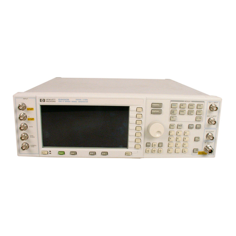
HP 8970B User manual

HP 8970B Option 020
Service Manual
Supplement


Service Manual Supplement
HP 8970B Option 020
HP Part no. 08970-90115
Edition 1
May 1998

ii HP 8970B Option 020 Service Manual Supplement
UNIX is a registered trademark of AT&T in the USA and other countries. OSF/Motif is a
trademark of the Open Software Foundation, Inc. in the USA and other countries.
© Copyright Hewlett-Packard Company May 1998
All rights reserved. Reproduction, adaptation, or translation without prior written
permission is prohibited, except as allowed under the copyright laws.
Printed in the UK.

HP 8970B Option 020 Service Manual Supplement iii
Printing History
Printing History
Date Manual
Edition Notes
May 1998 1 08970-90115

iv HP 8970B Option 020 Service Manual Supplement
List of Related Publications
About this Manual
This document is a supplement to the HP 8970B Noise Figure Meter Service Manual
(08970-90054) and provides information useful for operating the HP 8970B Option 020. It
also gives some troubleshooting tips.
HP Part Number Title
08970-90054 HP 8970B Noise Figure Meter Service Manual

Table of Contents
Page
Printing History.....................................................................................................iii
List of Related Publications ..................................................................................iv
About this Manual.................................................................................................iv
Block Diagram and Parts List....................................................................................1-1
Block Diagram.........................................................................................................1-2
Front End ................................................................................................................ 1-3
Material List ...........................................................................................................1-5
Theory of Operation.....................................................................................................2-1
General.................................................................................................................... 2-2
Adjustments....................................................................................................................3-1
General.................................................................................................................... 3-2
Input power detector Gain and Offset Adjustment............................................... 3-2
600 MHz SAW Oscillator Frequency Adjustment................................................. 3-3
Board Differences .........................................................................................................4-1
General.................................................................................................................... 4-2
Microprocessor Board .............................................................................................4-2
20 MHz IF Assembly (08970-60050)......................................................................4-3
Driver Assembly (08970-60089)............................................................................. 4-4
Fault-Finding Tips........................................................................................................5-1
General.................................................................................................................... 5-2
Filter (0955-0634) ...................................................................................................5-2
Input Assembly (08970-60097 or 08970-60125)....................................................5-3
YIG Tuned Oscillator (0955-0630)......................................................................... 5-4
Mixer (0955-0635)................................................................................................... 5-4
Isolator (0960-0638)................................................................................................ 5-5
4.5 GHz Low Pass Filter (9135-0169).................................................................... 5-5
Second Convertor (5086-7909) ...............................................................................5-6
600 MHz SAW Oscillator (08970-60093)...............................................................5-6
Board Details.................................................................................................................. 6-1

Contents-2 HP 8970B Option 020 Service Manual Supplement

1
Block Diagram and Parts List

1-2 HP 8970B Option 020 Service Manual Supplement
Block Diagram and Parts List
Block Diagram
Block Diagram
Figure 1-1: HP 8970B Option 020 Front End Schematic
2.05 GHz Low Pass Filter
4 - 6 GHz
Y.T.O
J1 J3
J5
J2
J4
MIXER LO
IF
RF
ISOLATOR I/P
O/P
4.5 GHz LPF
Second Convertor
600 MHz SAW
Oscillator
J5 J4 J3
J2
J1
INPUT ASSEMBLY
PAD 1
PAD 2
PAD 3
(924)
TO A4 ASSEMBLY
(925)
(926)
20 dB AMP (923)
+15 V (2)
DETECTOR (927)
-15 V (7)
W1
W2
W3
W4
W5
W6
W7
W8
W9
92
0
92
2
50 Ω
LO MONITOR

HP 8970B Option 020 Service Manual Supplement 1-3
Block Diagram and Parts List
Front End
Front End
Figure 1-2: HP 8970B Front End Schematic
10 dB 10 dB 10 dB
20 dB
2-7 GHz Isolator
4.5 GHz LPF
2nd Convertor
X 6
600 MHz
3.6 GHz
300 MHz
10 - 2047 MHz
2050 MHz LPF
INPUT ASSEMBLY
2 dB
Detector
Diode
Output
3.910 - 5.947 GHz
YTO Output
To A4 Assy
3.9 GHz
J3 J4
J5
J2
J1 Limiter
Limiter(on08970-60125
Input Assembly only).
Suppresses externally
generated transients.

1-4 HP 8970B Option 020 Service Manual Supplement
Block Diagram and Parts List
Front End
Figure 1-3: Schematic Representation of Input Assembly
This is a schematic representation of the RF input assembly. The amplifier section and
each and each of the attenuator sections are switchable by the control lines.
On units using the Input Assembly 08970-60125, the Limiter suppresses externally
generated transients.
In Figure 1-1 the numbers in brackets inside the input assembly refer to the wire colors.
The numbers at the side of the second convertor refer to the wire colors attached to the
connector which connects up to the second convertor.
10 dB
PAD 20 dB
AMP 10 dB
PAD 10 dB
PAD
Detector
3 GHz
LPF
2dB
PAD
PAD 1 20 dB
Amp PAD 2 PAD 3
Limiter
Limiter(on08970-60125
Input Assembly only).

HP 8970B Option 020 Service Manual Supplement 1-5
Block Diagram and Parts List
Material List
Material List
1. Replaces 08970-60097 from prefix break 3811.
2. This is the same part number as the main instrument but different wires are used. The wires
that are not used are tied back.
3. These replace 08970-80051/52
4. Replaces 08970-60003
5. Replaces 08970-60034
Table 1-1: HP 8970B Option 020 Material List - main differences for Option 020
Description Part Number Quantity
2.05 GHz Low Pass Filter 0955-0634 1
Semi-rigid cable W1 08970-20082 1
Input Assembly 08970-60097 1
Input Assembly 08970-6012511
2 to 8 GHz YIG Tuned Oscillator 0955-0630 1
YIG Tuned Oscillator Interface Board 08970-60045 1
YIG Tuned Oscillator Shield 08590-00047 1
Semi-rigid cable W2 08970-20081 1
Semi-rigid cable W3 08970-20083 1
Semi-rigid cable W4 08970-20085 1
Microwave Mixer 0955-0635 1
Semi-rigid cable W5 08970-20084 1
Microwave Isolator 0960-0638 1
Right Angle SMA(F) to SMA (M) Adapter W6 1250-1249 1
4.5 GHz Low Pass Filter 9135-0169 1
SMA(M) to SMA (M) Adapter W7 1250-2189 1
Second Convertor 5086-7909 1
600 MHz SAW Oscillator 08970-60093 1
Flexi Cable W8 83711-60035 1
Flexi Cable W9 83711-60035 1
Main Wiring Harness 08970-6004621
Firmware EPROM’s 08970-80071/7232
20 MHz IF Assembly 08970-6005041
Driver Board Assembly 08970-6008951
SMA (M) 50 ΩTermination 0960-0053 1

1-6 HP 8970B Option 020 Service Manual Supplement
Block Diagram and Parts List
Material List

2
Theory of Operation

2-2 HP 8970B Option 020 Service Manual Supplement
Theory of Operation
General
General
The input range of the instrument is 10 MHz to 2047 MHz.
The input signal is first low pass filtered, using the 2050 MHz filter, to avoid images.
The YIG tuned oscillator tunes over the range 3910 MHz to 5947 MHz to mix the
incoming signal to a first IF of 3900 MHz.
The isolator ensures that any rejected signals are absorbed in the isolator and do not
interfere with the front end detector circuitry.
The second convertor mixes 3900 MHz down to 300 MHz. There is a cavity tuned
bandpass filter which is tuned for 3900 MHz. This is set at the factory and should not be
adjusted. The LO input is 600 MHz, but this is multiplied up to 3600 MHz by a X6 circuit.
The 3600 MHz can be monitored at the LO Monitor port.
The 600 MHz supplied to the second convertor comes from a 600 MHz SAW Oscillator.
The frequency is adjusted for 600 MHz ±50 KHz. The power should be > -3 dBm.

3
Adjustments

3-2 HP 8970B Option 020 Service Manual Supplement
Adjustments
General
General
There are 2 adjustments that need to be made:
1. Input power detector gain and offset.
2. The 600 MHz SAW oscillator frequency adjustment.
Input power detector Gain and Offset Adjustment
Follow the adjustment procedure in section 5-13 of the Adjustments Chapter in the 8970B
Service Manual with the following exceptions.
Figure 3-1: Input detector gain and offset adjustment
1. The input level must be -21 dBm ±0.1 dB.
2. R32 is the offset adjustment.
3. R26 is the gain adjustment.
R32
R26
J1
RF Input
Assembly

HP 8970B Option 020 Service Manual Supplement 3-3
Adjustments
600 MHz SAW Oscillator Frequency Adjustment
Figure 3-2: 600 MHz SAW Oscillator Frequency Adjustment
1. Disconnect the 600 MHz SAW Resonator from the second convertor 600 MHz input.
2. On the 8568A. Press PRESET, CENTRE FREQUENCY 600 MHz, SPAN 500
KHz.
3. Connect the 600 MHz SAW Resonator to the 8568A RF Input.
4. Adjust R6 until the signal on the screen is 600 MHz ±50 KHz.
8568A
600 MHZ SAW
Oscillator
RF In

3-4 HP 8970B Option 020 Service Manual Supplement
Adjustments
600 MHz SAW Oscillator Frequency Adjustment
Table of contents
Other HP Laboratory Equipment manuals
Popular Laboratory Equipment manuals by other brands

Belden
Belden HIRSCHMANN RPI-P1-4PoE installation manual

Koehler
Koehler K1223 Series Operation and instruction manual

Globe Scientific
Globe Scientific GCM-12 quick start guide

Getinge
Getinge 86 SERIES Technical manual

CORNING
CORNING Everon 6000 user manual

Biocomp
Biocomp GRADIENT MASTER 108 operating manual