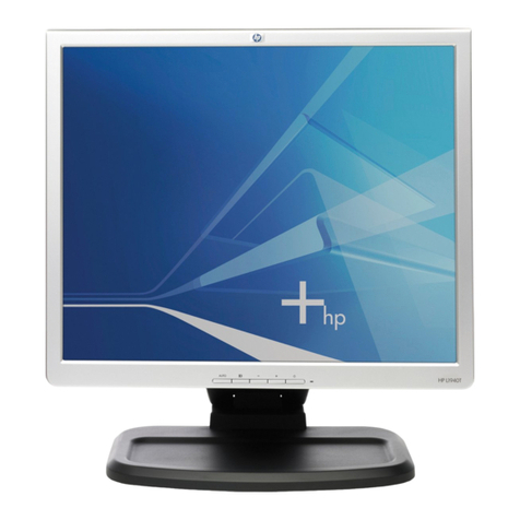
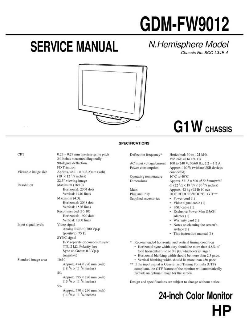
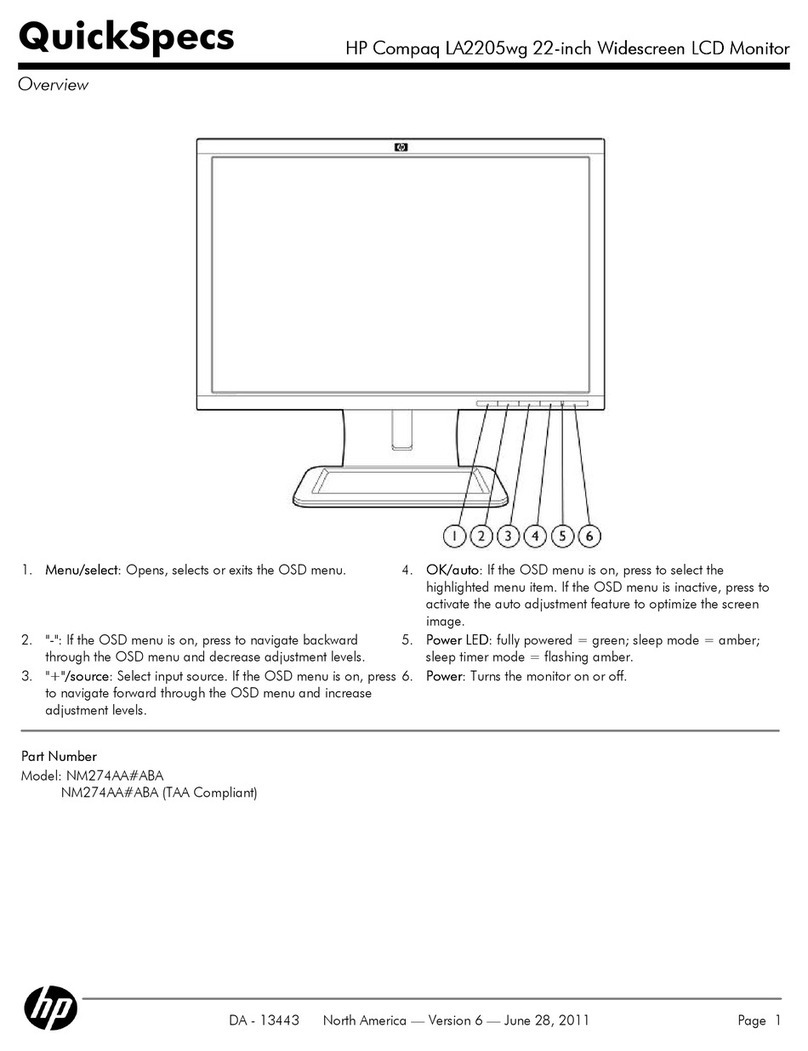
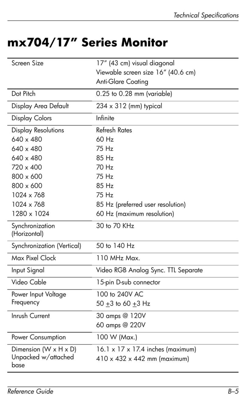
HP CRT Monitor s7500 User manual

17-inchColorMonitor
S7500/MV7500/CV7500
Service Manual

Page27
HPS7500/MV7500/CV7500
Service ManualVersionsandRevision
Copyright
Copyright2002LiteOnTechnologyCorp.
AllRightsReserved
Thismanualmaynot,inwholeorinpart,be
copied,photocopied,reproduced,translated,or
convertedtoanyelectronicormachinereadable
formwithoutpriorwrittenpermissionofLiteOn
TechnologyCorp.
HPS7500/MV7500/CV7500ServiceManual.
Printedin Taiwan.
Trademarks
LiteOnisaregisteredtrademarkofLiteOn
TechnologyCorp.
Allothertrademarksarethepropertyoftheir
respectiveowners.
No. Version Release Date Revision
1. 1.0 FEB. 27, 2003 Original release

Page1
HPS7500/MV7500/CV7500
TableofContents
1.Precautions.................................................................................................................2
2.ProductSpecifications..............................................................................................5
3.OperationTheory.....................................................................................................10
4.AlignmentsandAdjustments...................................................................................14
5.Troubleshooting........................................................................................................18
6.RecommendedSparePartsList..............................................................................24
7.BlockDiagram..........................................................................................................26

Page2
HPS7500/MV7500/CV7500
1Precautions
Followthesesafetyand servicing precautionstopreventdamageandtoprotectagainstpotentialhazards
suchaselectricalshockandX-rays.
1-1SafetyPrecautions
1-1-1 Warnings
1.Forsafetypurpose,do notattempttomodify
thecircuitboard,andalwaysdisconnecttheAC
powerbeforeperforming servicing on the
monitor.
2.Operationofthemonitoroutsideitscabinetor
withthecoverremovedinvolvestheriskof
shockhazard.Repairworkon themonitor
shouldonlybeattemptedbyservice personnel
who arethoroughlyfamiliarwithallnecessary
safetyprecautionsandproceduresforworking
onhighvoltageequipment.
3.DonotlifttheCRTby theneck.After
completelydischargingthehighvoltageanode,
handletheCRTonlywhenwearingshatterproof
goggles.TrytokeeptheCRTawayfromthe
bodyduringhandling.
4.Highvoltageshouldalwaysbekeptattherated
value,no higher.Onlywhenhighvoltageis
excessiveareX-rayscapableofpenetrating the
shelloftheCRT.Operation athigh voltages
mayalsocausefailureoftheCRTorhigh
voltagecircuitry.
5.TheCRTisespeciallyconstructedtolimit X-
rayemissionto0.5mR/HRat300microamperes
anodecurrent.ToensurecontinuedX-ray
protection,replacetheCRTwithonlythesame
orequivalenttypeastheoriginal,andadjustthe
anode’svoltagetothedesignatedmaximum
rating,nevertoexceed.
1-1-2Safety Checks
Beforereturningthemonitortotheuser,perform
thefollowingsafetychecks:
1.Inspecttomakecertainthateachleaddressis
notpinchedorthathardwareisnotlodged
betweenthechassisand othermetalpartsin
themonitor.
2.Inspectall protectivedevicessuchas
nonmetalliccontrolknobs,insulatingmaterials,
cabinetbacks,adjustmentand compartment
coversorshields,isolation resistor-capacitor
networks,mechanicalinsulators,etc.
3.ACLeakageCurrentCheck
AlwaysperformtheACLeakageCurrent
Checkon theexposedmetalparts,including
metalcabinets,screwheadsandcontrolshafts,
asfollows:
a)PlugtheAClinecorddirectlyintoarated
ACoutlet.Donotuseanisolation
transformerduringthecheck.
b)UseanACvoltmeterwithatleast5000
ohmspervolt sensitivityasfollows:
Connecta1500 ohms,10 watt resistor
paralleledbya0.15uFACcapacitorinseries
withall exposedmetalcabinetpartsand a
knownearthground,suchaselectrical
conductorelectricalground connectedto
earthground,asshownintheFigure1-1.
MeasuretheACvoltageacross the
combinationofresistorand capacitor.
c)ReversetheACplug attheACoutletand
repeatthestepsforACvoltage
measurementsforeachexposedmetalpart.
d)Voltagereadingmustnotexceed0.3volts
RMS,equivalentto0.2milliampereAC.Any
valueexceeding thislimit ill constitutea
potentialshockhazardand mustbe
correctedimmediately.
Figure1-1.SetUpForACLeakageCurrentCheck
To known
earth ground

1500 ohm 10 watt
0.15ufd
To exposed metal
cabinet part

Page3
HPS7500/MV7500/CV7500
1-1-3ProductSafety Notices
Manyelectricaland mechanicalpartsinthischassishavespecialsafety-relatedcharacteristicswhichare
oftennotevidentfromvisualinspection,theprotection affordedbythemmaynotbeobtainedbyreplacing
themwithcomponentsratedforhighervoltage,wattage,etc.Beforereplacing any ofthesecomponents,
consult theRecommendedSparePartsListgivenattheendofthismanual.Anyofthereplacementsthatdo
notprovidethesamesafetycharacteristicsmayresult inshock,fire,X-rayemission orotherhazards.
1-2ServicingPrecautions
Warning:Anelectrolyticcapacitorinstalledwiththewrongpolaritymightexplode.
Caution:Beforeperformingservicingcoveredbythisservicemanual,readandfollowtheSafetyPrecautions
section ofthismanual.
Note:If unforeseenconflictbetweenthefollowing servicing precautionsand any ofthesafety
precautions,alwaysfollowthesafetyprecautions
1.Followcloselytheservicingprecautionsprintedonthemonitorcabinetandchassis.
2.AlwaysunplugtheACpowercordfromtheACpowersourcebeforeremovingorinstallinganycomponent
orassembly,disconnectingPCBplugsorconnectorsand connecting atestcomponentinparallelwitha
capacitor.
3.Whenreplacing partsorcircuit boards,clamptheleadwiresaround thecomponentbeforesoldering.
4.Whenreplacing ahighwattageresistor(>0.5Wmetaloxidefilmresistor) inthecircuit board,keepthe
resistorabout1cm(1/2inch)awayfromthecircuitboard.
5.Keepwiresawayfromthehighvoltageorhigh temperaturecomponents.
6.Keepwiresintheiroriginalpositionssoastominimizeinterference.
7.Alwaysconnectatestinstrument’sgroundleadtotheinstrumentchassisgroundbeforeconnecting the
positivelead;alwaysremovetheinstrument’sground leadlast.
Afterputtingtherearcoverbackandmakesurethemonitorisworking properly,theHi-Pot&
Ground ContinuitytestsMUSTBE performedbeforethemonitorisreturnedtouser.
1-3Hi-PotTest
1.TestEquipment
PuncturetestmodelPM5530ADTorKIKUSUTOS-8750voltagetesterorequivalentapprovedequipment.
Note:Thetestequipmentmustbecalibratedinregularperiod.
2.TestSetup
a)Applyvoltage:DC2100 VDC
b)Testduration:3seconds
c)Cutoff currentshouldbesetto3mA
3.TestProcedure
a)UnplugpowercordfromACsource.
b)Putthepowerswitchofthemonitorinthe“ON”position.
c)Leavesignalcableun-connected.

Page4
HPS7500/MV7500/CV7500
d)Plug monitorpowercordtotheHiPottesterterminals.
e)Turnontesterandwatchtheindicatororbeeper.
f) Iftheindicatorlamplighten,orbeeperbeeps,thetestfails.
1-4Ground ContinuityTest
1.TestEquipment
AClowohmtesterTOS-6100 orequivalentapprovedequipment.
Note:Thetestequipmentmustbecalibratedinregularperiod.
2.TestSetup
a)Testduration:3seconds
b)Setcurrentlimit at25 A
c)Thegroundingresistancemustbelessthan0.1ohm.
3.TestProcedure
a)Plug themonitorpowercordtothetesterterminals.
b)Makesureall connectionsarewell-contacted.
c)Turnonmonitorpowerand testerpower.
d)Press“Test”button.
e) Ifgreenlightshowsup,meanstestOK.
Ifredlightshowsup,meanstestfails.
f) IftheTesterhasadigitaldisplay,theresistancevaluemustnotexceed0.1ohm.
Note:Besurenottotouchthemetalportionofthesignalcableheadduring testing.

Page5
HPS7500/MV7500/CV7500
2ProductSpecifications
2-1Specifications
Note:Abovespecificationsaresubjecttochangewithoutpriornotice.
Picture Tube
17-inch (16-inch Visual image area), sloted mask, 90 degrees
deflection, dot type black matrix, medium short persistence
phosphor, dark tint, non-glare/ anti-static screen,
0.27 mm dot pitch for E1770NSL/T and 0.25mm dot pitch for HP
S7500/MV7500/CV7500
Scanning Frequency VGA, Super VGA, 1024x768@60/70/75/85 Hz
1280x1024@60Hz
Maximum Resolution 1280 dots (H) x 1024 lines (V) @60Hz refresh rate
Display Area 306 mm (H) x 230 mm (V) typical
Display Characters 80 char. x 60 rows on a 10 x 10 matrix
Display Colors Analog
Input Unlimited Colors
Synchronizatin Signals Separate Sync: horizontal/vertical, TTL, positive or negative
Synchronization
Frequencies Horizontal : 30 to 70 kHz
Vertical : 50 to 140 Hz
Signal Connectors 15-pin, D-shell connector
Video Signals Analog : 0.7 Vp-p, RGB positive
Power Input 75 Watts (maximum) AC rated voltage, 100VAC to 240VAC
Misconvergence Center Area : <0.3 mm; Corner Area : <0.4mm
User Controls Power On/Off, Contrast, Brightness, Horizontal Size, Horizontal
Position, Vertical Size, Vertical Position, Pincushion, Trapezoid,
Rotation, Color temperature, Language, Display Frequency,
Degauss, Recall, H. Moire,
V. Moire
Service Controls PWB-1709
PWB-1707 : power voltage adjust (VR801)
Preset Modes 8 (see Table 2-2. Timing Chart)
Environmental
Considerations Operation temperature : 10oC to 40oC ambient
Operation Humidity : 20% to 80% ambient
Storage temperature : -40oC to 65oC ambient
Storage Humidity : 10% to 90% (non-condensing)
Altitude : Non operating 40,000 feet sea level
operating 10,000 feet sea level

Page6
HPS7500/MV7500/CV7500
2-2SignalCablePinConnections
Table2-1.SignalCablePinAssignment
Note*Thispinisusedforselftestdetection.ConnectthispintogroundatthePCend.
** ForPC99:Thispinwillprovide+5VfromPCside.
Pin Signal Pin Signal
1Red video 9** +5V
2Green video 10 Digital Ground
3Blue video 11 Ground
4Ground 12 SDA
5* NC 13 H-Sync
6Red ground 14 V-Sync/VCL
7Green ground 15 SCL
8Blue ground

Page7
HPS7500/MV7500/CV7500
2-3TimingChart
Thissection describesthetimingsthatthecomputerindustryrecognizesasstandardforcomputer-generated
videosignals.
Table2-2.TimingChart
H.Parameters:
A:Period B:BlankingTime
C:SyncWidthD:BackPorch
E:ActiveTimeF:FrontPorch
V.Parameters:
G:Period H:BlankingTime
I:SyncWidthJ:BackPorch
K:ActiveTimeL:FrontPorch
Seperate Sync
Horizontal
Video
C
D
E
Sync
A
B
F
Vertical
Video
I
J
Sync
G
H
L
K
Mode 1 2 3 4 5 6 7 8 9
H. Dots 640 720 640 640 800 800 1024 1024 1280
V. Dots 480 400 480 480 600 600 768 768 1024
H-freq (kHz) 31.47 31.47 37.5 43.27 46.8 53.67 60.02 68.68 63.98
Sync Polarity - - - - + + + + +
A period us 31.78 31.78 26.666 23.11 21.333 18.63 16.66 14.56 15.63
B Blanking us 6.356 6.356 6.349 5.33 5.172 4.409 3.657 3.725 3.778
C Sync us 3.81 3.81 2.032 1.556 1.616 1.138 1.219 1.016 1.037
D B.P. us 1.907 1.907 3.81 2.22 3.232 2.702 2.235 2.201 2.296
E Active us 25.42 25.42 20.37 17.78 16.162 14.22 13 10.836 11.852
F F.P. us 0.636 0.636 0.51 1.556 0.323 0.569 0.203 0.508 0.444
V-freq (Hz) 59.95 70.08 75 85 75 85 75.03 85 60.02
Sync Polarity -+- - ++ + + +
O Period ms 16.68 14.27 13.3 11.76 13.333 11.76 13.33 11.77 16.661
P Blanking ms 1.43 1.557 0.533 0.67 0.533 0.578 0.533 0.582 0.656
Q Sync ms 0.064 0.064 0.08 0.069 0.064 0.056 0.05 0.044 0.047
R B.P. us 1.02 1.08 0.427 0.578 0.448 0.503 0.466 0.524 0.594
S Active us 15.25 12.71 12.8 11.09 12.8 11.18 12.8 11.18 16.005
T F.P. us 0.35 0.413 0.027 0.023 0.021 0.019 0.017 0.015 0.016

Page8
HPS7500/MV7500/CV7500
2-4Power SavingFunction
Note:Themonitorwillbedriveninto“PowerSaving” modeby thecontrolsignalfromthedisplay
controller,asindicatedby theamber-colorpowerLED.
Table2-3.PowerSavingFunction
State Power
Consumption LED
Light
ON Normal*Green
Active
OFF <5 watts Amber
Thepowersaving stateswillbekeptuntil acontrolsignalhasbeendetectedorthekeyboardormouseis
activated.TherecoverytimefromActiveOFF statebacktoON stateisaround 10seconds.
*Forpowerconsumption :75WMax.(@230VAC,presetsize andmaximumlightoutputcondition)
2-5TCOVersion(Optional)
ThemonitormeetstheTCO95/99,NUTEKenergy saving,electricandmagneticfieldrequirements.
Alsoit iscompliantwithTCO95/TCO99 labelling scheme.
Theemissionfrommagneticandelectricfieldmustcomplywiththelimitsspecifiedby theSwedishBoard
forMeasurementand Testing,commonlyknownasMPR1990recommendations.Theselimitsaresum-
marizedintheTable2-4.
Table2-4.TCO95EmissionRequirements
VLF/TCO ELF/TCO
Magnetic Field 25 nT 200 nT
Electric Field 1 V/m 10 V/m
Frequency Range 2~400 kHz 5~2000 Hz
Value RMS RMS
Distance 30 cm 30 cm
Electrostatic
Potential +/- 500 V +/- 500 V
ThemonitorisdesignedwithselectedCRTandcarefullyroutedwiresaroundCRT,makesureexactlythe

Page9
HPS7500/MV7500/CV7500
sameroutingschemeisusedwhendoingCRTreplacement.
2-5-1TCO95 Version(Optional)
TheTCO95 schemeisforinternationalandenvironmentallabellingofpersonalcomputers.Thelabelling
schemewasdevelopedasajointeffortbytheTCO(TheSwedishConfederationofProfessionalEmploy
ees),Naturskyddsforeningen(TheSwedishSocietyforNatureConservation)and NUTEK(TheNational
BoardforIndustryandTechnicalDevelopmentinSweden).
1)`Scope
TCO95toucheson ergonomicqualities,emissions(electricalandmagneticfields),energyefficiencyand
ecology(withdemandsforenvironmentaladaptationforboththeproductand theproductionprocessesat
themanufacturingplant).
2)EnvironmentalRequirements
Themonitorabidesbytheenvironmentaldemandsconcerning restrictionson thepresence and useof
heavymetals,brominatedandchlorinatedflameretardants,CFCs(freons),andchlorinatedsolvents,among
otherthings.Themonitorisalsorecyclable.
3)EnergyRequirements
Themonitoralsofollowstheenergyrequirementsthat,afteracertainperiodofinactivity,themonitorshall
reduce itspowerconsumptiontoalowerlevelinoneormorestages.
4)Others
Themonitormeetsthestrictenvironmentaldemandsforthereduction ofelectricand magneticfields,
physicalandvisualergonomicsandgoodusability.
Table2-5.TCO95VisualErgonomics
Feature Standard Description
Linearity 1% or less Difference in length of columns or rows compared to the
corresponding lengths through the center of the monitor.
Display Luminance 100 cd/m2 (at least)
Luminance
Uniformity 1.7:1 or less The ratio is between the max to min luminance within the
whole active area.
2-5-2TCO99 Version(Optional)
TCO99will appendthecolortemperatureand energy efficiencyspecification,alsocovertheenvironmen-
talrequirement.

Page10
HPS7500/MV7500/CV7500
3OperationTheory
Thisisafullydigitalcontrolledmulti-synccolormonitorthatiscompliantwithDDC1and 2BPlugandPlay
VESAstandardand offersthefollowing mainfeatures.
3-1MainFeatures
1.Simplifieddesignwithminimumcomponents.
2.TheNOVA NT6865 32 processor-- thathasI2CBUScontrolledgeometriccorrection,contrastand
brightness--offersthefunctionsfor:(a)Contrast,(b)Brightness,(c)H-size,(d)H-position,(e)V-size,(f)
V-position,(g)Pincushion,and(h)Trapezoid.
Inaddition,it alsooffersmorefunctionsas:(a)Sync.processor,I/PandO/P,(b)Mute,(c)Powersaving
-Suspend&Stand-By,(d)Powersaving override,(e)DDC1/2B,(f)I2CBusforauto-alignmentthrough
signalcable(g)CS1/CS2/CS3/CS4forlinearityandsizecompensation.
3.Storesupto10factorypresetmodesand offers8usermodes.Thereare16functioniconsatOSD.They
arecontrolledby 12keyson frontpanel.
4.PowerfulPHILIPSTDA4863AJA5andTDA4841presentthefollowingusefulfunctions:(a)Pincushion,
(b)Trapezoid,(c)V-Position,(d)V-Size,(e)Vertical’s“C”and “S”correction -- factoryadjust,(f)
Pincushion’sV.position correction,(g)Cornercorrection --factoryadjust,(h)Pincushionunbalance
correction -- factoryadjust,(i)Parallelogramdistortion-- factoryadjust,(j)Moirecancellation,(k)X-ray
protection,and (l)Full horizontaland verticalautosynccapability.
5.Softwarecontrolledautoshutoff function activatediffH<=29 kHzand fH>=70 kHz.
6.FullrangeACinputandsimplifiedlinefilterdesign.
3-2MicrocontrolSection
1.ThismonitorusesNOVA NT6865 CPU.Itcontainsa80518-bit CPUcore,512 bytesofRAMusedas
working RAMand stackarea,32k bytesofMASKROM,10-channel8bit PWMD/Aconverter,4-
channelA/DconvertersforkeydetectionsavingI/Opins,internalH.syncandV.syncsignalsprocessor
providingmodedetection,andanI2Cbusinterface.WhenH/VsyncthroughD-Subsignalcableenterpin
41and pin42,theCPUperformsfrequency/polaritydetectionand calculateandsendtoH/VsyncOUT.
ThenCPUreadsthedatafromI703 andtransfertodevice4841 andsomeDACinCPU,aboveoperation
takesabout500ms.
2.Thereallowed8factorypresetmodesand8usermodes.Thereare11 functions,Contrast,Brightness,H.
Size,H.Position,V.Size,V.Position,Pincushion,andTrapezoid,Rotation,H.Moire,VMoire,allcontrolled
byOSDicon whichcanbeadjustedby user.
3.Thepin25 andpin26areusedforATE function.WhenCPUreceivesC6asslaveaddress,itwilloperate
inATEmodewhichisusedforauto-alignment.Afteralignmentthedatawill bestoredinI703.
4.Theusercontrolparametersareselectedby OSDicons,through 1&2keys,theyaredetected
bysensingthevoltagethroughR710,R740,R741,R743,J007,J008topin16and17 ofI701.
3-3DeflectionSection
1.I2C-- autosyncdeflectioncontrollerisTDA4841.
2.TheTDA4841 isahigh performance and efficientsolution forautosyncmonitors.All functionsare
controllableby I2Cbus.SDA and SCLsignalscomingfrommicroprocessorfeedtopin12 andpin13to
controlallfunctions.

Page11
HPS7500/MV7500/CV7500
3-3-1HorizontalSection
1.TheoscillatorisdrivenbythecurrentsinR419and R420.Theminimumoscillatorfrequencyisdetermined
byR419andthemaximumfrequencyisdeterminedbyR420.
2.Horizontalsyncgoesintopin15throughR318.Andhorizontalflybackpulsegoesintopin1throughR401
frompin5ofFBTforHFLBloop.
3.Horizontaldriver(pin8)O/PtoQ401viaC410.
3-3-2VerticalSection
1.Verticalsyncgoesintopin14throughR317.
2.Thefreerunningfrequencyisdeterminedby R301andC301.
3-3-3VerticalO/Psection
1.Thedifferentialoutputcurrentsfrompin13ofVout1and pin12ofVout2canbedirectlycoupledtothe
verticaldeflectionboosterpin1andpin2ofTDA4863 AJ.
2.TheTDA4863AJhastwooutputstageswhicharecurrentdriveninoppositephaseand operatein
combination withthedeflection coilinafullbridgeconfiguration.
3.ThisICispoweredbytwosetsofpositivevoltageand onesetofnegativevoltage.(+12Vatpin1,-12V
atpin4).
3-3-4E-W/TrapezoidandH.WidthControls
1.ThehorizontalO/PstageusesdiodemodulatorD419,C411,C412,L409 and C418 forEast-West
(Pincushion)TrapezoidandH.widthcontrols.
2.ThescancurrentisdeterminedbyB+minusVm(thevoltageofC418)valuesand thepincushion controlis
accomplishedby OPAMP(KA324)I402 and Q419 by coupling aparabolawaveformfrompin11 of
TDA4841.TheH.width/cornerandtrapezoidcorrectionarealsoaccomplishedby thispin11.TheDC
levelcontrolsH.size.TheACleveliscombinedwithsidepinand trapezoidcornersfunctions.
3-3-5X-RayProtection
1.ToavoidX-rayhazard,aDCvoltagegeneratedatpin5ofFBTandrectifiedby D410,C424anddivided
byR404,R406and R405comeintopin2ofTDA4841.
2.If thisvoltageishigherthan6.39V,thenTDA4841 will beactivatedtofloatHUNLOCK(pin17),H.
DRV(pin8),BDRV(pin6),VOUT1(pin12),VOUT2(pin13).Afterthatall deflection circuit stop
working.
3-3-6G1,Blanking andBrightness
1.Theverticalblanking signalcomesfromunlockpin17ofI401.ThispositiveverticalpulsesthroughQ405
amplifiedandconvertedintonegativepulseandsenttoG1forverticalblanking.
2.Inprotection modeoranout-of-rangesituation HUNLockwillsend5VpulsetoCPUpin30 ofI701,
thenG1will godownto-150V.During themodechange,MuteactsassameasHUNLock’s.
3-3-7ContrastSection
1.Contrastiscontrolledby I701throughI2CbustoI501(LM1237)directly.
2.BeamcurrentisdetectedthroughT402(FBT)pin7,C429,R449anddetectedvoltagefeedingintopin12
ofI403(KA324),R459,R548,C556tocontrolI501 pin22voltage.WhenI501 pin22voltagedrops

Page12
HPS7500/MV7500/CV7500
below4.0V,theABLfunctionwillhappen.
3-3-8H/Vsize breathingcompensation
1.Beamcurrentissensedasabovesection(3-3-7item2)and thisvoltageroutesthroughR451,R468,C470
thenthroughR437topin31ofI401 forH.size compensation.
2.HVvoltageisdetectedthroughT402(FBT)pin11.C481,R4F4,R4F8,C430,R411,pin5,6,7ofI403
(KA324)thenthrough R302toI401pin21forV.size compensation.
3-3-9Dynamicfocuscircuitry
Thedynamicfocusisappliedtoimprovethecornerfocusperformance,itincludeshorizontaland vertical
dynamicfocus.
1.HorizontaldynamiccomesfromIdy currentthroughT403,R434,C448,R428andfeedtoFBTdynamic
focuspin(T401pin12).
2.Verticaldynamiccomesfrompin32ofI401throughC315,R309,R326,R322,R323,Q301,R324,R325
and feedtoFBTdynamicfocuspin.
3-4Power SupplySection
3-4-1ACRectifier
Thecircuitcanaccept90Vto264VACinputthrough D801~D803 bridgediodesandC808 filtering toget
DC126V~364VforpowerconversioninT802.
3-4-2LineFilter
ItconsistsofC803,T801,C804,C805,C808,C819,C807,C817and meetsEMIregulation.
3-4-3PowerLEDStatus
1.TheLEDhas3leadswithcommon cathodetoemit greenand ambercolorlightfordifferentpower
saving states.Itiscontrolledby CPU.
2.Normal:Greenlight
AmberLEDisoff becauseCPUpin29is1.96Vand pin24is0.45V,onlygreenLEDisturnedon.
3.OffMode:Amberlight
CPUpin24 is1.87Vandpin29is0.46V,thengreenisoffand amberisilluminated.
3-4-4AutoDegaussing
WhenS801turnson,pin27 ofI701willsend asignaltoQ802andturnson RL801 fordegaussing.After4
seconds,itwillturnoffRL801automatically.
3-4-5PWMControl
1.StartUp
TheI801(5S0765C)getspowerfromR807,R808,C830and pin3voltagereaches15Vforstarting up.
TheI801 startsoscillationat20 kHz,pin1outputtodriveT802.Switchingon,R819 setupan15 Vto
keepI801workingthrough D809auxiliaryvoltage.

Page13
HPS7500/MV7500/CV7500
2.Regulation
TheDCO/Pvoltageisproportionaltotheauxiliaryvoltage,soI801 pin4sensesthefeedbackvoltage
fromthedividerD806,R809,C810,VR801,Q803,Q801and R821tocomparewiththebuilt-in1.5volts
referencevoltageforerroramplifieroperation.Finallypin6canmodulatethedifferentdutycycleby
VR801settingtoachieveregulationpurpose.
3-4-6Synchronization
1.NormalMode
ThesyncpulsefromFBT(31 kHz~69kHz)viaR812,R811 andC815 topin5ofI801 tokeepI801
synchronizedwithhorizontalsyncinputfrequency.
2.PowerSavingModes:Standby/Suspend
Becausethereisno pulsefromFBT,sothefree-run frequencySMPS worksat20 kHzby I801 itself.
3.Override
Thehorizontalfreerunfrequencyisabout63.2kHzunderoverridecondition,SMPS issynchronizedto
thisfrequency.
3-4-7O.V.P.
Iftheauxiliaryvoltageishigherthan25 voltsmakespin3ofI801 islimitedtohavetheOVPactivated.
3-4-8O.P.P.
Theexcess currentofT802 throughI801 pin1,2,makeVs>1.1VinternalofI801,thenlimitethepower.
3-4-9StepUpPowerSupplyForFBT
1.TheB+ofFBTisproportionaltohorizontalfrequency,thatisthehigherfrequency,thehighervoltage.
Thebasicvoltageis58voltsfromT802pin10viaL811,D813,C824andthegatecontrolofQ451 comes
fromI401 pin6viaQ450,Q434,Q435and R4E5.Thedutycycleiscontrolledby I701pin23(PWMpin
Adj.)viaR719,C741,R4F6,R4F5,R4F1.
2.Theregulation and boostup (from68Vto160Vormore,ondemand).TheH.V.issetat25 kV(zero
beam)by I701 pin23 whichsensesthesecondaryO/PfromFBT.TheboostercomprisesQ451,L410,
L411,D450,C425andT802 tooffertherequiredB+fordifferentfrequencymodes.
3-5VideoAmplifier Sectionand OSD(OnScreenDisplay)function
1.RGBsignalinputsareterminatedby R501,R531andR561 thenpassthrough thecoupling capacitors
C503,C533and C563toIC501LM1237preamplifier.
2.TheamplifierRGBsignals(0~3Vpp)areadjustedbyI2Cbus,I501pin23isforclamppulsewhichcomes
frompin16 ofTDA4841 tosetup equalclamplevel.
3.Thepre-ampvideostageisamplifiedby I501 (LM1237/NT6812),it’sincludingOSDfunctionandcontrol
byI701 pin12,13 (I2C).
4.Thevideooutputstage15isamplifiedby I502(LM2469/LM2466).
5.TheRGBcathodescutoffareadjustedbyI503(LM2480)pin8,7,6,whichcomesfromI501pin16,15,
14toadjustcutiff voltagelevelbyI2Cbus.
6.Underoverridecondition,“NOSIGNAL”willshowup onthescreen.

Page14
HPS7500/MV7500/CV7500
4AlignmentsandAdjustments
Thissectionoftheservicemanualexplainshowtomakepermanentadjustmentstothemonitorsettings.
4-1GeneralAdjustments
4-1-1AdjustmentConditions
a)PowerSupply
ApplyAC115Vor220V
b)Warm-upTime
Themonitormustbepoweredon for15minutesbeforestarting anyalignment,butrequires30minutesof
warm-up timeforconvergence adjustment.
c)SignalInput
1.Video:RGBAnalog,0.7Vp-p,positive
2.Synchronization:Horizontaland verticalTTLsignal,separate,positiveornegative
3.All adjustmentsshouldbemadeusing asignalofFH=68.68 kHz,FV=85 Hz,unless otherwise
defined.
4-1-2EquipmentRequired
Thefollowingequipmentsarenecessaryforadjustmentprocedures:
1.Volt-ohm-Ameter(SanwaFD-750Corequivalent)
2.30kVhighvoltageprobe(HP34111A)
3.Oscilloscope(TEK2235orequivalent)
4.MinoltaColorAnalyzerII
5.Signalgenerator(IBMPCwithproperdisplaycardsorChroma2000)
6.Screwdriver
4-1-3SwitchingPowerSupplyandRegulatorAdjustment
a.TheregulatedB+controlhasbeenpresetinthefactoryandneedsno adjustment.However,ifany repair
ismadeon thepowersupplysection,thefollowingreadjustmentproceduresarerecommended:
1.Allowthemonitortowarm-up forabout15minutes.
2.ApplyVGA(1024x768@68.68kHz/85Hz)signaltothemonitor.
3.ConnectaDCvoltagemetertoTP001(ontheMainboard),andadjustVR801for11.6±0.1Vdc
4.Ifafuseisbrokenduring adjustment,remembertoreplace itwiththeexactsametypeoffuse.
b.Ifnecessary,followthefollowingprocedurestoenterthefactorymode.
1.Press both1keyand 2keysimultaneouslythenpowerON.
2.Afterturnthepoweroff,thismonitorwillgobacktonormalmode.

Page15
HPS7500/MV7500/CV7500
4-2AlignmentProcedures
4-2-1HighVoltageAdjustment
CONDITION
Press 1and 2buttonssimultaneouslywhenswitchingthepower“On”.
Displayimage:Novideo(68.68kHzMode)
PROCEDURE
ConnectDCmetertoTP002 andadjustHV(i)
R802 toobtainaDCvoltageof-173.5±0.2VDC(Sampo FBT)or-172.5±0.2VDC(LCEFBT)forCPT
CRTM41AGE93X46(TCO)orM41AGE83X46 (MPRII) .
4-2-2ScreenandWhiteBalanceAdjustment
CONDITION
Press 1and 2buttonssimultaneouslywhenswitchingthepower“On”.
Displayimage:Novideo(68.68kHZMode)
PROCEDURE
1Rastercolorsetting
1-a.SetBrightnessmax.to77,G1to60(OSDcursor) and 530±5atG2,cursor.
1-bAdjustRand Bcutoff tomin.
1-cAdjustGcutoff toabout0.45FL
1-dAdjustBcutoff togety=298 ±5,Rcutoff togetx=283±5and Y=0.65 ±0.05FL.
1-eAdjustBrightnesscutoff toraster0.01-0.02FL.
CONDITION
Displayimage:50mmx50 mm whiteblockpattern
PROCEDURE
1 55000Kcolortemperaturesetting
1-a.SetBrightness tocutoffandContrasttomaximum.
1-bMovecursoronOSDtochoosecolortemperatureicon.
1-c.Withgreenblockpattern,adjustGgaintogetYabout32FL.
1-dAdjustR.B.gaintogetx=333 ±5,y=348 ±5;and Y=40 ±0.5FL
2 65000Kcolortemperaturesetting
2-a.SetBrightness tocutoffandContrasttomaximum.
2-bMovecursoronOSDtochoosecolortemperatureicon.
2-c.Withgreenblockpattern,adjustGgaintogetYabout32FL.
2-dAdjustR.B.gaintogetx=313 ±5,y=329 ±5;and Y=43 ±0.5FL
3 93000Kcolortemperaturesetting
3-a.SetBrightness tocutoffandContrasttomaximum.
3-bMovecursoronOSDtochoosecolortemperatureicon.
3-c.Withgreenblockpattern,adjustGgaintogetYabout32FL.

Page16
HPS7500/MV7500/CV7500
3-dAdjustR.B.gaintogetx=283±5,y=297±5;and Y=46±0.5FL
4Full whiteABLsetting
CONDITION
Displayimage:fullwhitepattern
4-aSetBrightness tocutoffandContrasttomaximum.
4-b.AdjustABLtoY=31FL±0.5FL.
4-c.Checkthewhitebalance at5FLand 28FL.
4-d.Repeatalltheproceduresin4-2-2section until thebestwhitebalance isobtained.
4-2-3FocusAdjustment
CONDITION
Displayimage:“me”characterpattern(68.68kHzMode)
PROCEDURE
1.SetBrightness tocutoffandContrasttomaximum.
2.Adjustfocus1atT402 (staticfocusVR)tomakeverticallineclear.
3.Adjustfocus2atT402 (staticfocusVR)tomakehorizontallineclear.
4.Repeataboveprocedurestogetbestfocus.
4-2-4StaticConvergenceAdjustments
Staticconvergence involvesalignmentofthered,blueandgreenlinesinthecenterarea ofthedisplay.
Note:Themonitorrequires30minutesofwarm-up timeforconvergence adjustment.
CONDITION
Displayimage:Crosshatchpattern
Warm-up Time:30 minutes
PROCEDURE
1.Setbrightnessandcontrasttodisplayawell-definedpattern.
2.Ensuretheconvergencemagnetringsarecorrectlypositionedon theCRT.
Figure4-1.ConvergenceMagnetsontheCRT
+
87654 3 2
10
1
11
CRT
FRONT
P
9
1) Setup Bolt 2) Bow Magnet 3) Band 4) 2-Pole Magnet
5) Spacer 7) Spacer
9) Holder 6) 4-Pole Magnet 8) 6-Pole Magnet
11) Tabs10) Band

Page17
HPS7500/MV7500/CV7500
4-2-5Degaussing
Degaussing isrequiredwhenpoorcolorimpurityappearson thescreen.Thismonitorusesanautomatic
degaussing circuitthatisactivatedwhenthepowerison.Theautomaticdegaussing willbefullyfunctional
againafterthemonitorhasbeeninoperation for20 minutes.
Thedegaussing effectisconfinedtothepicturetubesincethecoilsaremountedatthebackofthetube.
Shouldany partofthechassisorcabinetbecomesmagnetized,it isnecessarytodegauss theaffectedarea
withamanualdegaussingcoil.
4-2-6ManualDegaussing
1.Applylinevoltagetothedegaussingcoilandmoveit inarotarymotionoverthefront,sides,andtopofthe
monitor.Thecoilshouldbekeptawayfromtherearofthemonitortoavoiddamagingthemagneticneck
components.
2.Slowlyrotateandmovethecoilawayfromthemonitortoabout6feetbeyond thepointwherenoeffect
ontheCRTwillbenoticeable.
Forproperdegaussing,itisessentialthatthefieldbegraduallyreducedbymovingthecoilslowlyawayfrom
themonitor.Thedegaussingcoilmustneverbeshutoff ordisconnectedwhilenearthemonitor,asthiswould
introduce astrong fieldinsteadofcanceling theeffectofthestrayfields.
3.Rotatetheindividualringsof4-poleconvergencemagnetsbychangingthespacingbetweenthe2tabsto
convergetheverticalredandbluelinesatthecenterofthescreen.
4.Rotatethepairofringsof4-poleconvergencemagnetsby maintaining spacingbetweenthe2tabsto
convergethehorizontalredand bluelinesatthecenterofthescreen.
5.Rotatetheindividualringsof6-poleconvergencemagnetsbychangingthespacingbetweenthe2tabsto
convergetheverticalred,blueandgreenlines.
6.Rotatethepairofringsof6-poleconvergencemagnetsby maintaining spacingbetweenthe2tabsto
convergethehorizontalred,blueandgreenlines.
7.Repeatthestepsfrom3~6until thebestconvergence isobtained.
Figure4-2.4-poleand 6-poleMagnetsMovement
Note:The4-polemagnetsand the6-polemagnetsinteract,makingdotmovementcomplex.
Blue Red
Blue
Red
Red/
Blue Green
Red/
Blue
Green
4-pole magnets
movement
6-pole magnets
movement

Page18
HPS7500/MV7500/CV7500
5Troubleshooting
5-1NoRaster
Check voltage of
cathode, heater,
Grid 1, Grid 2, etc.
Check I401,
I703, R719, C741,
R4F6, R4F5, R4C4
Check
I801, R807,
R808, Q801,
Q802, ZD802,
VR801
Check D801,
D802, D803,
D804, T801,
R804, F801
Yes
No
Normal
(68 V, 31.5 kHz)
Short Circuit
at load?
Measure
voltage of B+ at
T402 pin 2 on
PWB-MAIN
No Raster
0 V High
(75 V or more)
Check DC
B+ line, Q451,
Q402, T402
Yes
Check voltage
of C808
No
This manual suits for next models
5
Table of contents
Other HP Monitor manuals