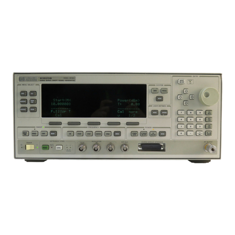
HP 3314A User manual

OPERATING
MANUAL
FUNCTION
GENERATOR
3314A
.
-
~
~
~
...
F/£JIj
HEWLETT
a.:~
PACKARD

~~~KL~6
------------.
MODEL
3314A
FUNCTION GENERATOR
OPERATING
MANUAL
Manual Part Number
03314
-90001
Microfiche Part Number
03314-90201
Copyr
ight
©,1
982,
1987
by
Hewlett
-Packard Company
8600
Soper Hill Road. Everett, Washington, U.S.A.,
98205
-1298
Printed in U.S
.A
.Printed:June
1987

_-------Flin-
HEWLETT
_
PACKARD
CERTIFICATION
Hewlett-Packard Company certifies that this product met its published specifications at the time
of
shipment
from
the
factory.Hewlett-Packard further certifies that its calibration measurements are traceable to the United States Na-
tional Bureau
of
Standards, to the extent allowed by the Bureau's calibration facility, and to the calibration facilities
of
other International Standards Organization members.
WARRANTY
This Hewlett-Packard product is warranted against defects in material
and
workmanship for a period
of
on
eyear
from date
of
shipment. During the warranty period, Hewlett-Packard
Company
will, at its option, either repair or
replace products which prove to be defective.
For
warranty service or repair, this
product
must be returned to a service facility designated by -hp-. Buyer shall
i
..my
shipping charges to -hp-
and
-hp- shall pay shipping charges to return the product to Buyer. However, Buyer
shall
pay
all shipping charges,duties,
and
taxes for products returned to -hp- from another country.
:
HP
software
and
firmware products which are designated by
HP
for use with ahardware product, when properly in-
stalled
on that hardware product, are warranted not to fail to execute their programming instructions due to defects in
materials
and
workmanship.
If
HP
receives notice
of
such defects during their warranty period,
HP
shall repair or
replace software media and firmware which do
not
execute their programming instructions due to such defects.
HP
does
not
warrant
that
the operation
of
the
software, firmware or hardware shall be uninterrupted or
error
free.
LIMITATION OF WARRANTY
The foregoing
warranty
shall
not
apply to defects resulting from improper or inadequate maintenance by Buyer,
Buyer-supplied software or interfacing,unauthorized modification or misuse, operation outside
of
the environmental
specifications for the product, or improper site preparation or maintenance.
NO
OTHER
WARRANTY IS EXPRESSED OR IMPLIED.
HEWLETT·PACKARD
SPECIFICALLY
DISCLAIMS
THE
IMPLIED WARRANTIES OF MERCHANTABILITY AND FITNESS FOR A PARTICULAR
PURPOSE.
EXCLUSIVE REMEDIES
',d E REMEDIES PROVIDED
HEREIN
ARE BUYER'S SOLE
AND
EXCLUSIVE REMEDIES.
HEWLETT-
,n -\CKARD SHALL NOT·BE LIABLE FOR ANY DIRECT, INDIRECT, SPECIAL, INCIDENTAL,
OR
CONSE-
,,JENTIAL DAMAGES,
WHETHER
BASED
ON
CONTRACT,
TORT,
OR ANY
OTHER
LEGAL
THEORY.
ASSISTANCE
Product maintenance agreements and other customer assistance agreements are available
for
Hewlett-Packard pro-
ducts.
For any assistance, contact your nearestHewlett-Packard Sales and Service Office.Addresses are provided at the back
of
this manual.

TABLE OF CONTENTS
Page
Nhat's
In This Manual .
rHE
3314A
FUNCTION GENERATOR 1
nstallation
Instructions
3
Ihe
3314A
Rear Panel 5
Ihe
3314A
Front Panel 6
V10des
of
Operation 8
How
to
Use
the
Free Run
Mode
9
Free Run
Summary
9
Hor
to
Use
the
Free Run
Mode
f
L..
.ear Sweeps) 10
U"'~ar
Sweep
Summary
11
(
How
to
Use
the
Free Run
Mode
(Log Sweeps)
12
Log
Sweep
Summary
12
How
to
Use the Gate
Mode
13
Gate
Summary.
. .
..
.
..
..
.
..
. .
...
.
...
13
How
to
Use
the
Gate
Mode
(Gated Sweeps)
14
Gate Sweep
Summary
.14
How
to
Use
the
NCycle
Mode
15
NCycle Summary 15
How
to
Use
the
1/2
Cycle
Mode
16
1/2
Cycle
Summary
16
How
to
Use
the
Phase
Lock
Modes.
... . . . . . 17
rse Lock
Summary
..
. . . . . ........ . . 18
H.
to
Use
the
ARB
Mode
19
hi
,B Mode
Summary
19
THE
WAVEfORM
LIBRARY 21
Free Run
23
1. Large Signal
With
Large DC
Offset
23
2.Small Signal
With
Large DC
Offset
-
23
3. Large Signal
With
Small DC
Offset
23
4.
TIL
(Squarewave
With
DC Offset)
23
5. ECL (Squarewave
With
DC Offset)
23
6. RAMPS (Variable
Symmetry
Triangle Wave)
24
7.
100%
Amplitude
Modulation
24
8.
AM
(Suppressed Carrier)
24
9.
AM
With
Function
Invert
24
10.
VCO
24
Page
Free Run (Unear Sweeps)
25
11 .
100Hz
to
1kHz
25
12
.Small Sweep Ratio
(1.06:
1)
25
13
.Large Sweep Ratio
(100
:1)
25
14
.
TIL
Level Sweeps
25
15.
TIL
Level,
95%
Symmetry
Sweep
25
Free Run (Log Sweeps)
26
16.
Sweeping a
Low
Pass Filter , 26
17.
1 Decade Sweep
26
18
.Audio Sweep
(20Hz
to
20kHz)
26
19.
Sub-Audio Sweep (2Hz
to
20Hz)
26
20
.
Low
Frequency
Sweep
(.2Hz to 2Hz)
26
Gate
27
21.
Gated Sinewaves
(Start/Stop Phase =-
45
0).• • •• • • •• • • •
27
22.
Gated Sinewaves (SYM =
95%)
27
23
.High Frequency Gate
27
24.
Gated
TIL
Level Pulses 27
25.
Gated
TIL
Level Pulses
27
Gated Sweeps-
28
26.
Basic Gated
Sweep
(1Oms)
28
27
.Small Ratio Gated
Sweep
(2:1)
28
28
.Large Ratio Gated Sweep (1
00:
1).
. . . . .
28
29.
Audio Chirp
28
30.
Swept
Squarewaves
28
NCycle
29
31.
3 Cycle Burst
29
32.
7 Cycle Burst
29
33
.2 Cycle Burst
29
34.
Haverslne
29
35.
4 Cycle Burst
With
Start/Stop
Phase = -
45%
29
1/2
Cycle
30
36.
Basic
1/2
Cycle
30
37.
Pulses
With
Overshoot.
..... . . . . . . .
30
38.
Pulses
With
Varying
Rise/Fall Ratios
30
39
.
1/2
Cycle
With
95%
Symmetry
30
40
.
1/2
Cycle Trianglewaves
30
Fin X N 31
41.
Squarewaves in Quadrature 31
42.
3 Pulses 31
43
.Trianglewaves 31
44
.Sinewaves 31
45.
Squarewaves 31

TABLE OF CONTENTS
(cont)
,Page
Fin +N"
32
46.
Squarewaves ,32
47.
Pulses.
.....
....
. . . . . ..... . .. . .
32
48.
Pulses
32
49.
Variable Symmetry
32
50.
Phase Locked Amplitude Modulation
32
ARB
33
51.
Exponential Charge/Discharge 33
52.
Square
Law
Response
33
53.Linear Steps
34
54.
Exponential Steps
34
56.
Exponential Response
35
56.Carotid
Artery
Pressure Wave
35
67.
sin(XI/X
36
58.3Note Chord (Major Triadl
37
6.9. Fourier Series Squarewave
CosF-
1/3cos3F
+1/5cos5FJ 38
eo,
Damped Oscillations
39
I
D.:.
{AILED OPERATING
INF..QRMA
TION 41
ARB ."43
Building an ARB Waveform
43
Recalling an ARB Waveform 46
Clearing an ARB Waveform 47
ARB Waveforms and the HP-IB 47
Definitions 47a
Calibration
48
CAlibrate
All
48
Amplitude
Calibration....
....
..
..
...
..
48
Frequency Calibration
49
Calibration Disable,
E04
60
Calibration Enable
50
Data
Entry....
......
......
.
.....
....
51
Modify
Knob.
........ . . . . . .......... 51
.' "'",nga Up or
Down
........... . ... . . . .51
'..-.ange Hold :.. 51
'\mplitude Range
52
;equency Range 52
Offset
Range.
...
. .
....
..
.......
...
.53
Symmetry .................... . . .. . 53
Error Codes
54
Errors While In Local
64
Errors While in Remote
54
Extemal Modulation 56
Amp
litude Modulation 56
Amplitude Modulation Suppressed
Carrier 58
Frequency Modulation 58
Voltage Controlled Oscillator 59
Page
Functions
60
Operating Characteristics
60
Mode '61
Free Run 61
Gate 61
N Cycle 61
1/2
Cycle '61
An X N.
...
.
.....
.. .
..
.
..
. .
..
•.
.. .
62
Fin +N
....
.
...
......
.
....
.•
. .
...
.
63
Operator Alerts
65
Alerts While Programming DC
Offset
65
Alerts While Programming the
Marker
Frequency...
...
..
..
..
..
...
..
65
Alerts While Changing Modes .. . . . . . . . . . .
65
Alerts While Entering Linear
or Log Sweep
66
Alerts When Programming ARB
Frequency
66
Outputs
67
Main Signal
Output
67
SYNC
Output
67
Trigger
Output
68
XAxis/Phase
Output
68
X3
Output
(Option
001
I 68
ZAxis
Output
69
Preset
70
How
to COMPLETELY Preset the
3314A
70
Specifications 71
Frequency Accuracy 71
Amplitude ............. . . . . . . .. . . ..
72
DC
Offset...
...
........
...
........
73
Symmetry .......... . . ... . ....... . .
73
Phase
74
Function Characteristics
74
InternalTrigger Interval
75
F~quency
Sweep
75
Modulation
75
Option
001-Simultaneous
X3
Output.
76
General
77
Store & Recall 78a
How
to
Store and Recall
Front Panel Settings 78a
How
to
Recall ARB Waveforms 78a
REMOTE OPERATION 79
The HP-IB 81
What
is the HP-IB 81
How Does the HP:IB Operate 81
HP-IB Specifications Summary 82
The
12
HP-IB Messages 83

TABLE OF CONTENTS
(cont)
Page
The
3314A
and
the
HP-IB
84
The
3314A's
HP-IB Capability
84
3314A1HP-IB
Verification
85
Analyzing Bus Problems
85
The
3314A's
HP-IB Address
86
How
to
View
the
3314A's
HP-IB Address
86
How
to Change the
3314A's
HP-IB Address
86
Listen
Only.
....................... .
87
Oevice/ListenlTalk Addresses
87
The
Clear Message
88
The Data Message
89
lData Message
(Immediate Execute Commands) 91
Page
The Data Message
(Function Select Commands)
92
The Data Message
(Data Entry Commands)
96
The Data Message
(Query Commands)
97
The Status Byte
98
The Trigger Message
99
Programming ARB
Waveforms
100
HP-IB Programming
Summary
blue
Sales and Support
Offices

WHAT'S
IN THIS
MANUAL
This manual contains
the
following
four
sections
to
help you operate
the
3314A:
THE
3314A
FUNCTION GENERATOR
an
introduction
to
3314A
operation
with
instructions
for
quick
and safe basic
operational checks.
THE WAVEFORM LIBRARY
sixty
oscillograms representing across section
of
the
3314A's
capabilities in-
cluding
control
settings
and HP-IB mnemonics.
DETAILED OPERATING INFORMATION
alphabetically organized
information
about
detailed
3314A
operation.
REMOTE OPERATION
information
to
program
the
3314A
using
the
HP-IB, including aProgramming
Summary
(blue pages).

THE
3314A
FUNCTION GENERATOR
The
3314A
is a
mul
ti-mode
,HP-IB
programmable
Function
Generator
featuring
Sine, Square and Triangle
functions
from
.00 1Hz
to
19
.99MHz
.
Sophisticated
im-
plementation
of
the
operating
modes
(see
below)
plus
precision
control
of
the
tr
ig-
ger signal
make
the
3314A
a flexible, easy
to
use
function
generator.
This
sect
ion
contains
information
about
the
following
subjects:
Installations
instructions
The
3314A
Rear Panel
The
3314A
Front
Panel
Modes
of
Operation
How
to
Use
the
Free Run
Mode
How
to
Use
the
Gate
Mode
How
to
Use
the
NCycle
Mode
How
to
Use
the
%Cycle
Mode
How
to
Use
the
Phase Lock
Modes
.
How
to
Use
the
ARB
Mode
1

INSTALLATION INSTRUCTIONS
These steps
will
let
you
install and make
the
most
basic operational checks. These
steps
constitute
the
minimum
safety
checks
that
must
be made
whenever
a
331
4A
is installed.
Note
that
the
3314A
is a
Safety
.Class 1
instrument
(provided
with
a
protective
earth terminal).
I
WARNING
The
3314A
should
never
be
connected
to an
AC
power
source
without
a
protective
earth
terminal. The chassis
and
all
exposed
shields are
connected
to the earth
terminal
and
"ttoetinq"
or
otherwise
defeating
this
safety
feature
may
subject
the
operator
to
lethal
voltages.
1.
Check
the
3314A
for
physical damage.
Under
no circumstances should adamaged
3314A
be
connected
to
power!
Refer
to
the
installation section
of
the
3314A
Ser-
vice
Manual. I
WARNING
The
integrity
of
the
protective
earth
ground
may
be
inter-
rupted
on a
3314A
that
is damaged. Under
no
cir-
cumstances
should
a
damaged
3314A
be
connected
to
its
AC
power
source.
2.
Check
the
line
voltage
selector on
the
rear panel. The selector
setting
should be
compatible
with
the
RMS voltage
of
your
AC
power
source.
The
3314A
can operate
from
AC
power
sources
with
voltage deviationsfrom +5%
to
-
10%
of
the selected .
value.
Connecting
a
3314A
to an
AC
power
source
with
the
in-
correct
voltage
selected
will
destroy
the
primary
fuse.
3

INSTALLATION INSTRUCTIONS
(cant)
3.Make sure
that
the line fuse is compatible
with
the
voltage selected.
Table
1.
Une
Fuse
Selection
s.mt
....
v
__
s.IectIlI
Faa
v.1ae
.Part
.....
less
than
100/
120V
O.SA SLO BLOW
2110-0336
2141AOO200
220/240V
OAA
SLO BLOW
2110-0340
2141 AOO200
100f120V
1
.0A
SLO BLOW
2110-0312
and
greater
220/240V
0
.5A
SLO BLOW
2110-0202
Using the
wrong
fuse value
or
fuse
type
will
not
protect
the
circuitry
inside
the
3314A
and
may
result
in damage to
your
3314A.
4.
Connect
the
power
cord. Please
contact
your
local -hp- Sales
Office
if
you
have any questions.
5. Set
the
LINE
switch
to
the
ON position. This
switch
is located in
the
upper
left
hand corner
of
the
front
panel. The
following
actions
will
occur:
-a 2 second
count
down
to
allow electrical stabilization and
test
the
front
panel LEOs
-a CAL ALL to generate afull complement of calibration
constants
-if
the
calibration failed,
the
appropriate error number
will
be displayed
for
1/2
second and the
3314A
will
try
to calibrate
itself
for
another
20
seconds or until acalibration is successful
6.
Connect
the
3314A
to an oscilloscope as
shown
in Figure 1 and
verify
that
the
3314A's
output
is a 1kHz,
10mVp-p
sinewave.Press the FUNCTION
key
to
cycle the
3314A's
function
to squarewave, triangle,
off
and back
to
sinewave. The FUNCTION key is located in
the
lower
right hand corner of
the
front
panel.
More detailed installation procedures are located in Section 2
of
the
Service
Manual.
4

INSTALLATION INSTRUCTIONS
(cant)
©
VERTICAL SENSITIVITY
2mV/DIV
HORIZONTAL TIME BASE 5ms/DIV
@
o
Operation Into II Hi Z load is allowed
except
that
the amplitude
will
be
twice
the
amount
displayed by
the
3314A
.The purity
of
the
functions at high frequencies
may
be degraded because
of the transmission line Impedance
mismatch
.
Figun
1.
Basic
Installation
Verification
THE
3314A
REAR
PANEL
ApI1 2•.
3314A
Rar
Pull
3
output
(only instruments
with
Option 001 have
this
output)
is a high voltage,
low
impedance
out
-
put
whose
output
voltage is 3 times
the
displayed
amplitude and
offset
whan
the
Main
Output
is
ter
-
minated
into
Son
.This
output
whose
capable
of
sourcing ±
30mA
peak
current
without
clipping.
The upper frequency
limit
is 1MHz.
X Axis
output
produces avoltage ramp from -5V
to +5V whose voltage isproportional to
the
sweep
frequency.This
output
isusefulto drivethe X
Axis
of
plotters and oscilloscopes.
Z Axis
output
produces voltage levels to
blank
(> +
5VI
or enhance «
-5V)
the
intensity
of
an
oscilloscopa display dur
ing
sweep
(intensifies
tha
marker
frequency and blanks the retrace) or ARB
(intensifies the current
vector)
.
HP-IBis used to control the operating
of
the 33
14A
from
aremote controller.This connector uses
metric
fasteners and is
not
compatible
with
older
cables using english threated fasteners.
Matric
fasteners are available
from
-hp-
to
upgrade older
cables.
5

THE
3314A
FRONT PANEL
Status
Q)
Store/Recall
Function
Internal
Trigger
0% to >
too%
0% to ±1%deviation
+
10%
to -80%. uaeabla
to
-1
00
%
External
Modulation
CD
AM
±1V
-
100%
FM ±1V - ±1
'llo
of range
veo
10%Nolt
The SfIC
OUTPUT.
ThIs
output
has a
characteristic
outpUt
Im-
pedance
of
600
when
terminated
Into
:s
500.
When
terminated
Into
>
500.
It
will
deliver
TTL
compatible
levels
of
0 to
>2.5V.The
maximum
unloaded voltage
Is
limited
to
-3V.
The edges
of
the
sync
slgnlll
are
coincident
with
the
peaka of
the sk\e and triangle
funct
lOlll
lind
coincident
with
the
edges
of
the
square
function.
This relationship Is
inverted
by Function
Invert.
The
lUll
OIJTPUT
.ThIs
output
has a
charlleterlatlc
output
Im-
pedance
of
600
.
Although
operation I
nt
o
other
than
500
II
allowed, the actual AC amplitude and DC
offset
will
be dff-
ferent
from
the
displayed values and
the
quality
of
the
func-
tions
will
be degraded
at
higher frequencies due
to
transm
is-
sion
Rne
Impedance
mismatches
.
The
SWJTR
IITYl
parameter
sets the period
of
the
internal
trig-
ger (note
that
the
Trigger
va
port
Is an
output
when
tNT trig-
ger
Is selected). This
output
signal Is
useful
as a
sync
signal
during
SWftllps
,
gate
and
burst
operstlone.
External
Trigger
One EXT
Trigger
Is e signalyou apply
to
the
Trigger
va
port
thet
88tlsities the selectable slope lind
threshold
conditlons
(note
that
the
Trigger Ifa
port
Is en
Input
when
EXT Trigger is
selectedl.
EXT
TrIggers ere level sensitive
for
Gate;
edge
sen-
sltlva
for Burst. Phese
Lock
and
Sweep
operations.
Up to 5.non-ARB
front
panel
control
sett
ings can be
stored
In
registers 1
through
5to be recalled .In
the
future
.Reg/ster 0is
reserved
for
the
front
panel
setting
at
power
off.
In
addit
ion. 6
ARB
waveforms
can
be
recalled
from
ARB registers 0through
5. ARB
waveforms
are
automatically
stored
as
they
ere
created,
Another
EXT Trigger is the
MAN
key.You
will
have
to
press
this key
twice
when
In Gate
mode
,to
simulate
a
complete
trig-
ger
cycle
(both
levels/. Once is
sufficient
for
all
other
opera-
tions
.The
min
imum
signal
that
will
conslstently
trlggM
the
3314A
is
~
JOOmVp-p. centered on
the
selected
trigger
threshold
voltage.
Thera are
two
EXT Triggers available
from
the
HP-IB,
the
Group
Execute
Trigger (GET) and
the
•
MN'
programming
com-
mend
.
6
CD
FiI X •
...
The
3314A
win phase lock
to
the
Trigger
(reference) signal lind
output
a
trequancy
,N"
times
the
reference
frequency
. The N
parameter
sets '
N'
from
1
to
1999.
The
frequency
limits
for
both
the
3314A
and
the
reference are
from
60Hz
to
20MHz.
See
•
How
to Use
the
PHASE LOCK
Modes
w•
Fill + •
.....
The
3314A
wlH phaee lock
to
the
Trigger
{r" -ence) signal and
output
a
frequency
equal
to
the
rt.
.
enca
frequency
divided by , W . The N
parameter
sets
,
N'
from
1
to
1999.
The
frequency
limits
for
both
the
3.
JA and
the
reference lire
from
60Hz
to
20MHz
.See
'huw
to Use the PHASE LOCK
Modes'
.
All
.....
The ARB
mode
redefines
the
3314A
as an
Arbitrary
Waveform
Generetor. The
output
waveform
consists
of
a
series of
voltage
ramps celled
vectors.
The
operator
hIlS con-
trol
over
the
number
of vectors,
the
18ngth
of
each
vector
In
time and
the
height
of
each
vector.
Both
continuoua
ARB
func-
tions
{FREE RUN
Model
and
gated
ARB (GATE Mode) ere
allowed.
See '
How
to Use the ARB
Mode'
.
The
3314A
has 7basic operating
modes
.The trigger signal,
either
the
331
4A'
sinternal trigger source or an external signal
you supply, is essential
to
every operating
mode
except
FREE
RUN w
ith
sweep
off.
FREE
lUI
.....
The
3314A
outputs
continuous
Sine,Square,
Triangle or ARB
functions
.Continuous
functions
,
sweeps
and
ARB operations are
allowed.
See '
How
to Use
the
FREE RUN
Mp<iew•
!
GAtt
.....
The
output:
isW
gated'
ON and OFF by
the
Trigger
Ir '. Gated
functions,
sweaps
and ARB operations are
allow
-
e...
5ee'
How
to
Use
the
GA
TEo
Mode
W•
This group
contains
the HP-IB
status
indicators
and
the
LCL
key to
switch
control
of the
3314A
from
remote to
front
panel
operation.
When
the
LCL key is preceded by the BLUE
shift
key, the
3314A
displays
its
HP·IB address
for
1/2
second. The
HP-lB address is
set
from
the
front
panel and stored innon-
volatile
memory
.The
factory
setting
Is7.See W
How
to
Change the
3314A's
HP-IB
Addresa"
located
In
the
HP-IB sec-
tion
of this manual.
Mode
The Preset
key
Initializes the
3314A
to
its
basic operetlng
state.
This
feature
is esp&Clelly
useful
to
quickly
recover
from
complex
operating
states
.
Preset
ICya.E
.....
The
3314A
outputs
a
burst
of N
complete
cycles
of the selected
function.
starting
when
a
Trigger
edge is
received. The N
parameter
sets the
number
of
cycles
from
1 to
1999
.The
start/stop
phase Is set
with
the Phase
parameter
from
·90 °
to
+
90
0•
See'
How
to Use the NCYCLE
Moda
w•
1/2
CYClE
ModI..
The
331
4A
outputs
alternate
1/2
cycles
of
the
selected
funtlon
when
aTrigger edge fs received. The
start
phase
of
the
first
1/2
cycle
(and
the
stop
phase
of
the
second
1/2
cycle) is
set
with
the
Phase
parameter
from
.90
0
to
+90°.
See
'How
to
Use
the
1/2
CYCLE
Mode
w•

Entry/Sweep
®
Modify
MIG(
UP
tr
DOWI
(1
or
I)
keys muttlpty or divide
the
displayed
value by
10
untit the
3314A's
operating limits are reeched.
this
provides an extremely fest method to
modify
the
displayed parameter.
Most
of
the
keys /nthis group are select keys for varieble en-
tries.The top
row
contains select keys
for
the
more universal
pararneters. Note
that
the blue
shifted
definition ofthe98 keys
presets the parameter. The second
row
contains the select
keya for the
3314A
's
sweep capabfilties. The SWfTR INTVL
key
Is
the
select key
for
the
sweep
Interval(SW INTVLJ and
for
the
internal
trigger
interval (TR INTVLI .When ARB is active,
the
sweep
functions are redefined
to
ARB functions.The keys are
renamed by the labels be
low
them.
®Range
All variable parameters (selected by keys in the Entry Group)
are entered Into the
3314A
using the
Modify
knob or the I or
Jkeys.These controls change the value of the displeyed
operating parameter.The
Modify
knob has 2 basic operating
modes called
"Cursor"
and
"Multi
Speed" .
CURSOR
(a dig
it
is flashing) .This mode isuseful when making
small changes or changes of
constant
Increments.The flashing
cursor dlglt is Incremented or decremented by 1 whenever
rotation of the Modify knob Is sensed. The - end -
keys
move
the cursor through the display.
MULTI
SPEED
(no d
igit
la flashing).
this
mode Is useful
when
making large chenges. The least significant
digit
In the dlspley
Is"incremented or decremented 1, 2, 4, 8, 16 or 32
times
faster
depending upon
how
fast
you
tum
the
Modify
knob.
IWIG£
HOlD
Inh
ibits
autCHsnging of Frequency (8 ranges),
Amplitude
14 renges), and/or DC
Offset
(2 ranges)
when
the8e
p
~
"
'''meters
are changed
with
the
Modify
knob. When in An X
r.
td
Fin +N,
FrllQ1.l&nCY
Range Hold also Inhi
bit
sauto-
acquisition.
FlpI1
2b,
3314A
FI'OIt
Pt.,
7

JUlJLJl
MM
ARB
Mode.
The
3314A
is redefined as an
Arbitrary
Waveform
Generator capable
of
producing
user
defined
waveforms.
MODES
OF OPERATION
Fin
+N
Mode.
The
3314A
output
frequency
is
locked
to
and ,.
liN"
times
the
reference
frequency.
Fin
X N
Mode.
The
3314A
output
frequency
is
locked
to and
"N"
times
the
reference
frequency.
112
CYCLE
Mode.
The
33l4A
output
signal is alternate
1/2
cycles.
FREE
RUN
Mode.
The
33l4A
output
signal is
continuous
or
swept.
GATE
Mode.
The
3314A
output
signal is gated ON or OFF.
N
CYCLE
Mode.
The
3314A
output
signal is a
counted
burst
of
"N"
cycles.
8

HOW
TO USE THE
FREE
RUN MODE
3
1
4o
500
FEEDTHRU TERMINATION {OptiOllllIl Not
shown
on
BUC-
ceedlng drawings. Trigger from CluJnnel 2on the rising edge.
@
2
3
4
PRESET
FUNCTION
FREQ
AMPTD
OFFSET
SYM
{blue
shlftl
FUNCTION
Sets
the
3314A
to Its basic operstlng state. This operating
state
Is
very
useful as
the common starting polnt
for
all operations.Note
that
FREE RUN is
the
active mode
sfter
instrument preset.
Press this key to changa
the
function
from
Sine to Square
to
Triangle to Function
OFF and beck to SIne. Note
that
DC OFFSET Is
not
affected
by Function OFF.
Use
the
Modify
knob and Ior Ikeys to cluJngs
the
valua
of
theso parameters.
Note
that
AMPTD and OFFSET ara completely independent paramaters end
that
variable
symmetry
18
not allowed
for
frequencies
~
2MHz
.
Function Invert Inverts
the
outpUt
signal. Note
that
DC OFFSET is
not
Inverted
and
that
the
inversion is
with
respect to
the
SYNC
output.
Free Run Summary
Functions:Sine, Square, Triangle, Function
Off
Frequency:
.001
Hz to
19.99MHz
In 8ranges
Amplitude: .OOmVp-p to
10.00Vp-p
In 4 renges
Offset
:±.
OOQ
VDC
to
±6.QOVDC In 2 rllnges
Symmetry
:
5""
to 96'10
for
frequencies <
2MHz
See
waveforms
1through
lOin
the Waveform
Ubrllry
.
9

A
500
FeedthN Termination Is optional
to
reduce
the
sensittvlty of the oscilloscope's ZAxIs Input.
Trigger
from
Channel 2 on
the
rising edge. I
I
I
I
I
I
I
I
I
I
I
I
I
I
I
I
I
I
©
©
o
@
When manuel sweep is ON, the
output
frequency Is lim
it
ed
to
frequencies
between
the Start and Stop Frequenclas. The XAxis
output
tracks
these
changes. This mode
Is useful wh8f1 setting up plotters
and
other
X,V displays.
When the EXT Trigger is selected. the
BW&8P
Is from
Start
Frequency to
Stop
Fre-
quency In this time. The
3314A
wlll
output
the
Start Frequency until another EXT
Trigger ill received.
ThIs parameter sets
the
sweep
tlme
interval.
The ZAxis
output
signal
will
Intensify the
trace
when
the
sweep
frequency equals
the Marker Frequency.
When
the
lNT
Trigger Is
elected,
the
sweep
is from
Start
Frequency to
Stop
Fre-
quency In
this
time. The sweep is repeated
lifter
the frequency resets. The reset time
Is approximately
101f1
of the sweep Intervel.
10
Theae
two
keys set
the
sweep limits. Note
that
chaoglng one parameter wnl
C8US6
the
other to change If
the
ratio of Stop Frequency to Start Frequency would be <1
or >tOO. The 331
4A
will
make
the
other pararneter'a
light
fillsh to alert you
to
thIs
automatic parameter change.-
Sets
the
3314A
to
Its basic operating state.
Thls
operation state Is very useful as
the common starting
point
for
all operations.Note
that
FREE
RUN Ie the
active
mode
after
instrument
preset.
The
3314A's
output
frequency ia
now
Rnaarly sweeping
from
the Start Frequency to
the
Stop Freqeuncv inthe time interval set by SW/TR INTVL.
!=flEQ
MKR
FREQ
STOP
FREQ
HOW
TO
USE THE
FREE
RUN MODE
(LINEAR SWEEPS)
MAN
SWEEP
SW/TR
INTVL
START
!=flEQ
SWEEP
PRESET
1
4
6
6
4
2
3

HOW
TO USE THE
FREE
RUN
MODE
(LINEAR SWEEPS)
(cant)
Linear Sweep Summary
Stop
Frequency
mlnlt
be
~
Start Frequency.
Stop Freq +
Start
Freq ratio is from 1 to
100
.
Sweep
Intervalrenge is
from
7.2Oms
to
19999
Sweep Is repetltlva
when
tNT Trigger III
selected
.
Sweep started by the Trigger when EXT Trigger Is selected.
See
Wavefonns
11 through 16 In the Waveform Ubrery.
11

See
Wllvoforma
16
through
20
In
the
Waveform
Ubrary.
Log
Sweep
Summary
@
Z AXIS INPUT
o
@ @
2
Trigger
from
Channel 2on
the
rising &dge.
The Z
Axis
output
IIlgnal lntenslflell
the
trace
when
the
Sweep
Frequency Is equal
to
the
Marker
Frequency.
Seta
the
3314A
to
its
basic operating
state.
ThIs operating state III
very
useful
811
the
common
starting
point
fOf an
operations
.
Note
that
FREE RUN Is tha
active
mode
after
instrument
pc-eset.
Thla
parameter
seta
the
sweep
time
Interval
axactfy
all it
was
Implemented In
Unear
SWHP
except
that
the
time
fa
now
the
time
per
decade.The
lower
limit
is
40.Omsldecade.
Note
that
the
Stop
Frequency sets the
number
of
decades
swept.
The
mantlsla
of
the
Stop
Frequency
trackll
the
Stert
Frequency.
12
The
3314A'S
output
frequency
III
now
sweeping
Iogerithmlcally
from
the
Start
Frequency
to
the
Stop
Frequency In the
time
Interval eet by SWITA INTVL.
Setting
the
Start
Frequency elso
lists
the mantissa of
the
Stop
Frequency (Log
sweeps
must
be
decade
sweepsl.
When
the
Start
Frequency fa changed,
the
Stop
Frequency
automatIcally
tracka
these
changes.
Note
that
the
lower
Stert
Frequency
limit III .2ooHz.
HOW
TO USE THE
FREE
RUN MODE
(LOG SWEEPS)
Stop
Frequency
must
be
greater
than
the
Start
Frequency.
Sweeps
are
decedes
,
only
.1
decade
to
7decades.
Start
Frequency range:
.200Hz
to
1.999MHz
.
Stop
Frequency range: 2Hz
to
19.99MHz.
Sweep
Interval
range:
40
.Oma
to
19998
per decade.
SUp
by
PRESET
2(blue
shift)
SWEEP
3START
FREQ
4STOP
FREQ
,. 5SWITR
,INTVL
6MKR
FREQ

HOW
TO USE THE GATE MODE
o
2
1
4
©@@
2
3
4
PRESET
GEN
SWfTR
INTVL
PHASE
Trigger
from
Chann&! 2 on
the
rising
edge
.
Presets
the
3314A
to e
common
mrtlng
point.
ThIs key toggl&s
the
mode
betwHn
Free Run and Gate. The
3314A'.
output
will
be
ON
when
the
trigger
leonI
satisfies
the
slope and
ttveshold
conditions.
Sets
the
period
of
the
Internal Trigger tnterval.The internal
trigger
signal has a
50%
duty
cycle
and
the
output
is
gated
on
for
slightly >
1/2
of
the
TrltJger Interval.
Sets
the
start
end
atop
phase of
the
gated
signal. The
output
Is QlIted on Immedlete-
Iy
after
the
trigger level Is
true.
The
output
Is gated
off
after
the
trigger level is
felH
and
the
output
algnal reaches
the
stop
phase.
Gate
Summary
Trigger
Lev&!
gatea
on
and
off.
SWrrR
INTVL:
.002ms
to
19998
Start/Stop
Phatl8:
-90
0
to
+
90
0
Internal
Trigg«
Duty
Cycle: slightly >
50'*'
Trigger
light
Indicates
the
presenca
of
a
trigger
SYNC
output
Is also
gated
See
Waveforms
21
through
25
In
the
Waveform
Ubrery.
13

@
o
@ @
3
Tligger
from Channel 2 on the rlslng edge.
This parameter
sets
the
Trigger Interval (the
time
between
sweep
starts). The
actual
time the
output
Is gated on Ithe sweep interval) Is
-.9
of
ths
TrltJger Interval.
Gated Sweeps ara useful as
·ll6"
-wlndow
lng·
signals
with
sampling Fourier
type
spectrum analvzers, such as the -hp-
3582A
.
Se"
-wlndowlng
slgnsls are needed
when
the analyzer's sampflng rate and the stimulus are unrelated.
ThIs key toggles
the
mode between Free Run and Gate. The
3314A's
output
will
be
ON
when
the trigger level satisfies the slope and threshold conditions.
Presets
the
3314A
to a common starting
point
.
HOW
TO USE THE GATE MODE
(GATED SWEEPS)
SWITR
INTVl
SWEEP
PRESET
GEN
1
2
4
14
2
3
SW/TR INTVl:7.2Oms to
1999s
Start/Stop
Phase: not meaningful
Internal Trigger
Duty
Cycle:-
90%
Gated Log Sweeps are
not
allowed.
Trigger
Ught indicates
the
presence of a
trigger
SYNC
output
Is also gated
See
Waveforms
26
through
30
In
the
Waveform
Ubrary.
Gated
Sweep
Summary
Table of contents
Other HP Portable Generator manuals
Popular Portable Generator manuals by other brands

Chicago Electric
Chicago Electric 95960 Set up, operating, and servicing instructions

Powermate
Powermate PM0495501.01 user manual

Energx
Energx DYNA DP3000 Operation and maintenance instructions

maxwatt
maxwatt MX3200i Operator's manual

Hyundai power products
Hyundai power products HG2700-A Original instructions

Pinnacle Aquatic
Pinnacle Aquatic HYPROLYSER Compact 240 user guide

Kipor
Kipor Sinemaster IG2600h Operation manual

Lincoln Electric
Lincoln Electric INVERTEC 165S Operator's manual

LeCroy
LeCroy WaveStation 2052 Operator's manual

ETQ
ETQ Liquid Propane Operation manual

Rheinland Elektro Maschinen
Rheinland Elektro Maschinen GSEm 4500 SB owner's manual

ITC Power
ITC Power SL-S400 user guide