manuals.online logo
Brands
  1. Home
  2. •
  3. Brands
  4. •
  5. HP
  6. •
  7. Server
  8. •
  9. HP ProLiant SL4540 Manual

HP ProLiant SL4540 Manual

Other manuals for ProLiant SL4540

2

This manual suits for next models

2

Other HP Server manuals

HP NetServer LH3 User manual

HP

HP NetServer LH3 User manual

HP cc2300 User manual

HP

HP cc2300 User manual

HP Enterprise HPE Edgeline EL8000t User manual

HP

HP Enterprise HPE Edgeline EL8000t User manual

HP ProLiant BL465c Gen8 Manual

HP

HP ProLiant BL465c Gen8 Manual

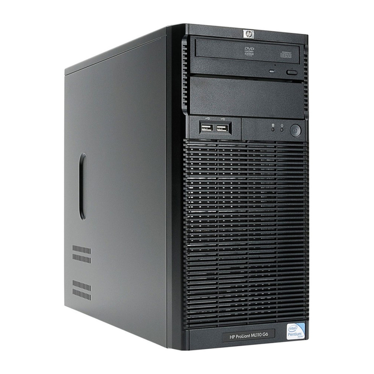
HP ProLiant ML110 - G2 Server User manual

HP

HP ProLiant ML110 - G2 Server User manual

HP D7171A - NetServer - LPr User manual

HP

HP D7171A - NetServer - LPr User manual

HP ProLiant BL660c Gen9 Manual

HP

HP ProLiant BL660c Gen9 Manual

HP ProLiant DL360 Gen10 User manual

HP

HP ProLiant DL360 Gen10 User manual

HP ProLiant DL560 Gen11 User manual

HP

HP ProLiant DL560 Gen11 User manual

HP NetServer AA 4000 Instruction Manual

HP

HP NetServer AA 4000 Instruction Manual

HP ProLiant DL120 G7 User manual

HP

HP ProLiant DL120 G7 User manual

HP D7171A - NetServer - LPr User manual

HP

HP D7171A - NetServer - LPr User manual

HP 2G Technical manual

HP

HP 2G Technical manual

HP ProLinant SL2500 Gen 8 Installation instructions

HP

HP ProLinant SL2500 Gen 8 Installation instructions

HP Compaq t5300 Manual

HP

HP Compaq t5300 Manual

HP rp7440 User manual

HP

HP rp7440 User manual

HP cc2300 User manual

HP

HP cc2300 User manual

HP T5135 - Compaq Thin Client User manual

HP

HP T5135 - Compaq Thin Client User manual

HP D7171A - NetServer - LPr User manual

HP

HP D7171A - NetServer - LPr User manual

HP ProLiant DL160se - G6 Server Reference manual

HP

HP ProLiant DL160se - G6 Server Reference manual

HP ProLiant s6500 Reference manual

HP

HP ProLiant s6500 Reference manual

HP DL385 - ProLiant - G5 User instructions

HP

HP DL385 - ProLiant - G5 User instructions

HP 195294-001 - ProLiant - ML370R Operating and safety instructions

HP

HP 195294-001 - ProLiant - ML370R Operating and safety instructions

HP D7171A - NetServer - LPr Parts list manual

HP

HP D7171A - NetServer - LPr Parts list manual

Popular Server manuals by other brands

Lenovo ThinkServer RD230 manual

Lenovo

Lenovo ThinkServer RD230 manual

Avocent CPS810 Installer/user guide

Avocent

Avocent CPS810 Installer/user guide

Dell PowerEdge R6615 Installation and service manual

Dell

Dell PowerEdge R6615 Installation and service manual

FreeWave HT2+ installation guide

FreeWave

FreeWave HT2+ installation guide

GIGA-BYTE TECHNOLOGY G492-Z50 user manual

GIGA-BYTE TECHNOLOGY

GIGA-BYTE TECHNOLOGY G492-Z50 user manual

Lanner HTCA-E400 user manual

Lanner

Lanner HTCA-E400 user manual

Bull NovaScale T840 E2 user guide

Bull

Bull NovaScale T840 E2 user guide

Asus RS740-E70RS24-EG Configuration guide

Asus

Asus RS740-E70RS24-EG Configuration guide

Meinberg LANTIME M300/TCR manual 

Meinberg

Meinberg LANTIME M300/TCR manual 

ZyXEL Communications VANTAGE RADIUS 50 user guide

ZyXEL Communications

ZyXEL Communications VANTAGE RADIUS 50 user guide

Lantronix xDirect-IAP quick start guide

Lantronix

Lantronix xDirect-IAP quick start guide

Fujitsu PRIMEQUEST 2400E3 General description

Fujitsu

Fujitsu PRIMEQUEST 2400E3 General description

IBM 9040-MR9 manual

IBM

IBM 9040-MR9 manual

IBM 306m - eServer xSeries - 8849 user guide

IBM

IBM 306m - eServer xSeries - 8849 user guide

green hippo Hippotizer Nevis+ quick start guide

green hippo

green hippo Hippotizer Nevis+ quick start guide

IBM 8203-E4A Brochure & specs

IBM

IBM 8203-E4A Brochure & specs

Ruijie Cloud Class RCD6000E V3 Series user manual

Ruijie

Ruijie Cloud Class RCD6000E V3 Series user manual

Avid Technology FastServe user guide

Avid Technology

Avid Technology FastServe user guide

manuals.online logo
manuals.online logoBrands
  • About & Mission
  • Contact us
  • Privacy Policy
  • Terms and Conditions

Copyright 2025 Manuals.Online. All Rights Reserved.

Quick Setup Instructions
HP ProLiant SL4500 Series
Part Number: 683986-002
November 2012
Edition: 2
*683986-002*
683986-002
Site requirements
Select an installation site that meets the detailed installation site requirements
described in the site planning guide on the Documentation CD and on the HP
website (http://www.hp.com).
Verifying the pallet contents
Item Description
1 The HP ProLiant SL4500 Series chassis
2 Node
3* Hard drive blank
4* Hard drive
5* Power supply blank
6 Management module
7* Power supply
8 I/O module
9 System fans (5)
10 Access panel
11** Rack rails and cable management arm
12** Documentation CD
* The quantity depends on the conguration ordered.
** Not shown
Chassis component identication
Before installing front or rear components into the chassis, review device bay
numbering for each component.
Front panel components
Item Description
1 Node hard drives
2 LFF drive health LED
3 LFF drive UID
4 Drives controlled by the array controller
a. Port 1i
b. Port 2i
5 Drive display boards
6 Node VGA connector
7 Node USB connectors
8 Node power on/standby button and system power LED
9 Node health LED
10 Node release button
11 Node UID LED button
Conguration rules
• Fans must be installed in all fan bays to meet thermal requirements.
• An I/O module or I/O blank must be installed in all I/O bays.
• A power supply or power supply blank must be installed in all power
supply bays.
Rear panel components
Item Description
1 System fans
2 I/O module
3 Management module
4 Power supplies
Device bay numbering
© Copyright 2012 Hewlett-Packard Development Company, L.P.
The information contained herein is subject to change without notice. The only
warranties for HP products and services are set forth in the express warranty
statements accompanying such products and services. Nothing herein should
be construed as constituting an additional warranty. HP shall not be liable for
technical or editorial errors or omissions contained herein.
Setting up the chassis
WARNING: The chassis is very heavy. To reduce the risk of personal
injury or damage to the equipment:
• Observe local occupational health and safety requirements and
guidelines for manual material handling.
• Remove all installed components from the chassis before installing or
moving the chassis.
• Use caution and get help to lift and stabilize the chassis during
installation or removal, especially when the chassis is not fastened
to the rack.
WARNING: To reduce the risk of personal injury or damage to the
equipment, you must adequately support the chassis during installation
and removal.
1. Select the proper location for the setting up the chassis, based on
requirements provided in the HP ProLiant SL4500 Series Setup and
Installation Guide.
2. Remove the packing materials from the pallet.
3. Remove any installed components from the chassis:
o Chassis hard drives
o Node
o System fans
o I/O module
o Management module
o Power supplies
Installing the chassis
The chassis requires installation in a rack. Install the rack rails, and then install the
chassis and other components.
For more information, see the HP ProLiant SL4500 Series Setup and Installation
Guide and the Quick Deploy Rail System Installation Instructions that ship with the
rack hardware kit.
Installing the front components
CAUTION: To prevent improper cooling and thermal damage, do not
operate the HP ProLiant SL4500 Series unless all hard drive and device
bays are populated with either a component or a blank.
Add any ordered options to the node.
Installing the node into the chassis
Install the component as indicated.
Translated versions
To view, select a language:
• English (http://www.hp.com/support/SL4540_4545_QSI_en)
• Français (http://www.hp.com/support/SL4540_4545_QSI_fr)
• Español (http://www.hp.com/support/SL4540_4545_QSI_sp)
• Deutsch (http://www.hp.com/support/SL4540_4545_QSI_gr)
•  (http://www.hp.com/support/SL4540_4545_QSI_jp)
•  (http://www.hp.com/support/SL4540_4545_QSI_sc)
Installing a hard drive
To install the component:
1. Prepare the drive.
IMPORTANT: The chassis supports up to 30 SAS or SATA hard drives per
hard drive backplane. Always populate hard drive bays from the rear to
the front starting with the highest device bay ID number. All unpopulated
drive bays require drive blanks to properly distribute air ow and cool the
installed drives.
2. Install the drive.
3. Determine the status of the drive from the drive LED denitions.
Installing the rear components
CAUTION: To prevent improper cooling and thermal damage, do not
operate the chassis unless all bays are populated with a component or
a blank.
Installing the system fan
To install the component:
Push in on the tabs, and then insert the system fan into the chassis.
IMPORTANT: Use the tabs to insert the system fan into the chassis. Do not
push in on the system fan grill to install it.
Installing a power supply
WARNING: To reduce the risk of electric shock or damage to the
equipment:
• Do not disable the power cord grounding plug. The grounding plug is
an important safety feature.
• Plug the power cord into a grounded (earthed) electrical outlet that is
easily accessible at all times.
• Unplug the power cord from the power supply to disconnect power to
the equipment.
• Do not route the power cord where it can be walked on or pinched
by items placed against it. Pay particular attention to the plug, electrical
outlet, and the point where the cord extends from the server.
To install the component:
Insert the power supply into the device bay, and then press rmly until the power
supply is seated.
Installing an I/O module
WARNING: To reduce the risk of electric shock, re, or damage to the
equipment, do not plug telephone or telecommunications connectors into
RJ-45 connectors.
To install the component:
1. Release the I/O handle, and then push the I/O handle down.
2. Insert the I/O module into the chassis, and be sure it is fully seated.
3. Push the I/O module handle up to lock it into place.
Installing a management module
To install the component:
1. Be sure the handle is in the down position.
2. Insert the management module into the device bay, and press rmly until
the module is seated.
3. Press the handle up to lock it into place.
4. Secure the management module to the chassis.
Powering up the system
1. Connect the power cables to the power supplies.
2. Connect the power cables to the power source (UPS or wall outlet) or to
an installed PDU.
3. Press the Power On/Standby button on the node.
Conguring the chassis
For more information on setting up and conguring your system, see the HP ProLiant
SL4500 Series Setup and Installation Guide.
For more information
For more detailed setup and conguration information, see the HP ProLiant SL4500
Series Setup and Installation Guide. For safety information and regulatory notices,
see the relevant chapter of the setup and installation guide and node user guide on
the Documentation CD that ships with the chassis and on the HP website
(http://www.hp.com).
Documentation feedback
HP is committed to providing documentation that meets your needs. To help
us improve the documentation, send any errors, suggestions, or comments to
Documentation Feedback (mailto:[email protected]). Include the document
title and part number, version number, or the URL when submitting your feedback.