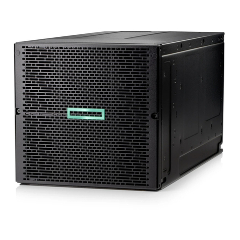
HPE Synergy 12Gb SAS Storage User manual

HPE Synergy 12Gb SAS Storage
User Guide
Abstract
This document is for the person who installs, administers, and troubleshoots the HPE Synergy 12Gb SAS Connection Module, HPE
Synergy D3940 Storage Module, and HPE Smart Array P542D RAID Controller for the HPE Synergy 12000 Frame. Hewlett Packard
Enterprise assumes you are qualified in the servicing of computer equipment and trained in recognizing hazards in products wi
th hazardous
energy levels.
Part Number: 789815-001
September 2016
Edition: 1

© Copyright 2016 Hewlett Packard Enterprise Development LP
The information contained herein is subject to change without notice. The only warranties for Hewlett Packard Enterprise products and services
are set forth in the express warranty statements accompanying such products and services. Nothing herein should be construed as constituting
an additional warranty. Hewlett Packard Enterprise shall not be liable for technical or editorial errors or omissions contained herein.

Contents 3
Contents
Product overview ......................................................................................................................................5
Synergy SAS Storage features ................................................................................................................................5
HPE Synergy 12Gb SAS Connection Module..........................................................................................................5
Features ........................................................................................................................................................5
Front panel and LED definitions ....................................................................................................................6
HPE Synergy D3940 Storage Module......................................................................................................................6
Features ........................................................................................................................................................6
Front panel components................................................................................................................................7
Front panel and LED definitions ....................................................................................................................7
Side panel......................................................................................................................................................8
Device bay numbering...................................................................................................................................9
Hot-plug drive LED definitions.......................................................................................................................9
VRM.............................................................................................................................................................10
HPE Smart Array P542D RAID Controller..............................................................................................................10
Features ......................................................................................................................................................10
P542D controller components .....................................................................................................................11
Planning..................................................................................................................................................13
Wiring diagram .......................................................................................................................................................13
Synergy D3940 drive count and performance details ............................................................................................16
Synergy SAS storage solution planning guidelines................................................................................................16
Server profile ..........................................................................................................................................................17
Local storage configuration options.............................................................................................................17
Server profile mobility..................................................................................................................................17
Logical JBOD drive selection.......................................................................................................................17
Deployment.............................................................................................................................................18
Installing Synergy SAS storage solution components............................................................................................18
12Gb SAS Connection Module installation guidelines ................................................................................18
D3940 Storage Module installation guidelines ............................................................................................19
Installing drives............................................................................................................................................20
Smart Array P542D Controller installation guidelines..................................................................................21
Configuration ..........................................................................................................................................................22
Firmware bundle..........................................................................................................................................22
Logical interconnect groups.........................................................................................................................23
Enclosure group ..........................................................................................................................................26
Logical enclosure.........................................................................................................................................29
Check alerts.................................................................................................................................................30
Server profiles .............................................................................................................................................34
Inventory.................................................................................................................................................................40
Interconnect.................................................................................................................................................40
Drive enclosure............................................................................................................................................40
Operations ..............................................................................................................................................42
Status event notifications .......................................................................................................................................42
Receiving event notifications through OneView GUI...................................................................................42
Receiving event notifications through OneView RESTapi...........................................................................43
Firmware ................................................................................................................................................................44
Updating the firmware .................................................................................................................................44
Expanding local storage .........................................................................................................................................44
Manually managed ......................................................................................................................................45
HBA .............................................................................................................................................................45
RAID ............................................................................................................................................................45
Replacing Synergy SAS storage solution components ..........................................................................................45
Replacing 12Gb SAS Connection Module...................................................................................................45

Contents 4
Replacing D3940 Storage Module ..............................................................................................................46
Replacing D3940 I/O adapter......................................................................................................................48
Electrostatic discharge............................................................................................................................49
Preventing electrostatic discharge .........................................................................................................................49
Grounding methods to prevent electrostatic discharge ..........................................................................................49
Specifications..........................................................................................................................................50
Environmental specifications..................................................................................................................................50
12Gb SAS Connection Module specifications........................................................................................................50
D3940 Storage Module specifications....................................................................................................................50
Smart Array P542D Controller specifications .........................................................................................................51
Documentation and troubleshooting resources ......................................................................................52
HPE Synergy documentation .................................................................................................................................52
HPE Synergy Configuration and Compatibility Guide .................................................................................52
HPE OneView User Guide for HPE Synergy...............................................................................................52
HPE OneView Global Dashboard................................................................................................................52
HPE Synergy Software Overview Guide .....................................................................................................52
HPE Synergy Glossary................................................................................................................................53
HPE Synergy troubleshooting resources ...............................................................................................................53
Troubleshooting within HPE OneView.........................................................................................................53
HPE Synergy Troubleshooting Guide..........................................................................................................53
HPE Error Message Guide ..........................................................................................................................53
HPE OneView Help .....................................................................................................................................53
HPE Synergy Quick Specs.....................................................................................................................................53
Support and other resources ..................................................................................................................54
Accessing Hewlett Packard Enterprise Support.....................................................................................................54
Information to collect ...................................................................................................................................54
Accessing updates .................................................................................................................................................54
Websites.................................................................................................................................................................54
Regulatory information............................................................................................................................55
Safety and regulatory compliance ..........................................................................................................................55
Belarus Kazakhstan Russia marking......................................................................................................................55
Turkey RoHS material content declaration.............................................................................................................56
Ukraine RoHS material content declaration ...........................................................................................................56
Warranty information ..............................................................................................................................................56
Acronyms and abbreviations...................................................................................................................57
Documentation feedback ........................................................................................................................59
Index .......................................................................................................................................................60

Product overview 5
Product overview
Synergy SAS Storage features
Synergy SAS Storage supports the following types of devices that are designed for use in an HPE
Synergy 12000 Frame:
•HPE Synergy 12Gb SAS Connection Module (on page 5)
•HPE Synergy D3940 Storage Module (on page 6)
•HPE Smart Array P542D RAID Controller (on page 10)
HPE Synergy D3940 Storage Module is a 40 SFF drive bay module, and the HPE Synergy 12Gb SAS
Connection Module is a connection module that allows direct attached storage for up to 10 compute
modules per frame.
Synergy SAS storage is optimized for use as either a direct attached storage array or as software-defined
storage using HPE StoreVirtual VSA or similar solutions.
Storage modules connect to compute modules within a frame through the HPE Synergy 12Gb SAS
Connection Module. Any number of drive bays in a storage module can be composed with any compute
module for efficient use of available drives. Synergy SAS storage can scale up to 160 SFF drives with four
storage modules in a single HPE Synergy 12000 Frame. Adding a second I/O adapter and second SAS
connection module provides a redundant path to SAS drives inside the storage module, ensuring high
availability.
HPE Synergy 12Gb SAS Connection Module
The following components are located in the HPE Synergy 12Gb SAS Connection Module.
Features
•Hot Pluggable connection module for HPE Synergy 12000 Frame
•Dual Domain direct attached SAS architecture supported with HPE Synergy D3940 Storage
Modules containing two I/O adapters
•12 internal blade bay ports each containing 4x 12Gb/s SAS links
•Managed with HPE Synergy Composer and OneView version 3.0 or higher

Product overview 6
Front panel and LED definitions
Item LED Status Definition
1
UID
Off
Normal
Solid blue
Being identified
Flashing blue
Firmware is being updated
2
Health
Off
Not powered up
Green
Healthy
Flashing amber
Error, there is a problem with the module
HPE Synergy D3940 Storage Module
The following components are located in the HPE Synergy D3940 Storage Module.
Features
•The HPE Synergy D3940 Storage Module holds up to 40 hot plug SFF drives in a half-height
double-width storage module designed for HPE Synergy 12000 Frames.
•Support for 12G and 6G SAS and SATA HDDs and SSDs.
•Simple configuration and setup with HPE Synergy Composer
•Easy to maintain and troubleshoot with industry standard management tools including HPE System
Insight Manager.
•Optimized for use with HPE StoreVirtual VSA software to create a robust shared storage
environment inside and across Synergy Frames.
•HPE Synergy D3940 Storage Module supports mixing of different drive types (SAS/SATA,
SSD/HDD) in a single enclosure.
NOTE: A composed logical drive or logical JBOD can be created using either a SAS SSD,
SAS HDD, SATA SSD, or SATA HDD drive type.
•The modular design of the Synergy D3940 Storage Module allows the drive drawer to slide out to
service drives or I/O adapters without interrupting the operation of other drives in the module.

Product overview 7
Front panel components
Item Description
1
Storage module handle
2
Storage module handle release latch
3
Drive drawer handle release latch
4
Drive drawer handle
5
Product information tag
Front panel and LED definitions
The front panel and LED layout shown in the following illustration is an example. Depending on your
specific model, the LEDs might be different.

Product overview 8
Item LED Status Definition
1
Drawer status*
Solid green
Drive drawer is closed
Flashing green
Drive drawer is open
Flashing amber
Thermal warning, close the drive drawer
2
UID
Solid blue
One or more drives are being located
Flashing blue
Firmware flash in progress
Off
No drives are being located
3
Health status
Green
Normal operation
Flashing amber
Degraded condition
Flashing red
Critical condition
4
Drive status (in
priority order)
Solid amber
One or more drives failed
Flashing amber
One or more drives are predicted to fail
Flashing green
One or more drives are rebuilding or transforming
Solid green
One or more drives are members of a logical drive
Off
No drives are configured by a RAID controller
5
Drawer power
Green
Storage module is in use, do not remove
Off
Storage module is not in use, safe to remove
*The drive drawer must be closed within five minutes after it is opened.
Side panel
The side panel layout shown in the following illustration is an example. Your specific model might be
different.
Item Description
1
I/O adapter health LED

Product overview 9
Item
Description
2
I/O adapter bay 1
3
I/O adapter bay 2
Device bay numbering
•40 hot-pluggable small form factor drive bays
oFor proper air flow, drives must be populated from back to front. Per the drive numbering below,
begin populating bays 33 through 40, and continue to populate back to front, finishing with bays 1
through 8.
oDrive blanks are not required or provided.
•2 hot-pluggable I/O adapter bays
oThe first I/O adapter must be installed in I/O adapter bay 1.
oI/O adapter blanks are not required or provided.
oI/O adapter health status is solid green or blinking amber.
Hot-plug drive LED definitions
Item LED Status Definition
1
Locate
Solid blue
The drive is being identified by a host application.
Flashing blue
The drive carrier firmware is being updated or requires an
update.
2
Activity ring
Rotating green
Drive activity
Off
No drive activity
3
Do not remove
Solid white
Do not remove the drive. Removing the drive causes one or
more of the logical drives to fail.

Product overview 10
Item
LED
Status
Definition
Off
Removing the drive does not cause a logical drive to fail.
4
Drive status
Solid green
The drive is a member of one or more logical drives.
Flashing green
The drive is rebuilding or performing a RAID migration, strip size
migration, capacity expansion, or logical drive extension, or is
erasing.
Flashing
amber/green
The drive is a member of one or more logical drives and predicts
the drive will fail.
Flashing amber
The drive is not configured and predicts the drive will fail.
Solid amber
The drive has failed.
Off
The drive is not configured by a RAID controller.
VRM
The VRM provides power to the D3940 Storage Module drive drawer by converting the 12 V input power
to the local power required by the drives and I/O adapters.
HPE Smart Array P542D RAID Controller
The following components are located in the HPE Smart Array P542D RAID Controller.
Features
•Storage interface (SAS/SATA)
o16 12Gb/s SAS physical links distributed equally across 2 x4 internal ports and 2 x4 external
ports

Product overview 11
o12Gb/s SAS technology delivers up to 1200 MB/s theoretical bandwidth per physical link
o6Gb/s SATA technology delivers up to 600 MB/s theoretical bandwidth per physical link for
directly attached SATA drives
•Mix-and-match SAS and SATA drives to the same controller. Deploy drive technology as needed to
fit the computing environment
•RAID 0, 1, 10, 5, 50, 6, 60, 1 ADM, 10 ADM
•Recovery ROM protects against ROM corruption
•Capable of supporting legacy and UEFI boot operation
•RAID or HBA mode
•HPE SSD Smart Path
•Optional HPE SmartCache
•Optional HPE Secure Encryption
•PCIe Gen3 x8 link
•If there is an unexpected power outage, 2GB FBWC provides read ahead caching and write back
caching with indefinite write cache data retention
•Manually managed features
oP542D internal ports
oRAID 50 & 60
oSmart cache (requires license)
oFBWC (other than default setting)
oStripe Size (other than default setting)
oSpare drive
oSpare activation modes
oMultiple logical drives in a single array
P542D controller components

Product overview 12
Item Description
1
SAS connector, port 4i
2
SAS connector, port 3i
3
Fabric connector
4
PCIe connector

Planning 13
Planning
Wiring diagram
Before planning a frame level layout for your storage and compute modules, it is helpful to understand
some basic principles of how the frame is designed and how the connections are made between compute
and storage modules. D3940 Storage Module may be connected to any P542D Controller equipped
compute module that is installed in the same frame with the following configuration options:
•Redundant pairs of HPE Synergy 12Gb SAS Connection Module
•Nonredundant single HPE Synergy 12Gb SAS Connection Module
As a best practice, Hewlett Packard Enterprise recommends designing your storage fabric for full
redundancy; however, nonredundant solutions are supported with the correct configuration. In the
following figure you will see how the fabric allows for connections to single or dual I/O adapters in each
storage module, as well as routing required in nonredundant connections.
When configured for redundancy two connection modules are configured in the frame residing in ICM
bays 1 and 4, and each storage module contains a pair of I/O adapters. This provides dual paths for each
P542D controller to be able to connect with any storage module in the frame regardless of where in the
frame the storage module is configured. However, when there are configurations where there is either
only a single connection module present or the connection modules and storage modules are configured
nonredundant, make sure that the storage modules are aligned in the correct module bays to be serviced
by the correct connection modules.
A SAS Connection module in ICM bay 1 will provide connection from the primary I/O adapter to any
storage module in device bays 1-6. For device bays 7-12, ICM bay 1 is routed to the secondary
(redundant) I/O adapter. In a nonredundant storage fabric configuration, the secondary connection would
not be active. Likewise, a SAS connection module ICM bay 4 will offer to connect to the primary I/O
adapter of a storage module any place in device bays 7-12, but will not access the primary I/O adapter in
Bays 1-6. If redundancy is not configured if the SAS fabric, it is required that connection modules in ICM 1
will only support storage modules in device bays 1-6 and connection modules in ICM 4 will only support
storage modules in device bays 7-12.

Planning 14
This routing does not impede compute module access to a storage module regardless of where the
storage module is located. For example, a compute module in device bay 1 will connect to a storage
module in device bay 11, even in a nonredundant configuration, as long as the connection module is
correctly placed in ICM 4 to align with the location of the storage module.

Planning 15
Front view HPE Synergy 12000 Frame device bays
Back view HPE Synergy 12000 Frame ICM bays

Planning 16
Synergy D3940 drive count and performance details
The drive count and workload details in the following illustration are examples. The drive ratios listed are
not fixed ratios and are only examples of an even distribution of drives across available compute modules.
Item Total D3940 drive bays Average Drive Count1Maximum Performance
per Compute Module2
1
40 SFF drives
4 SFF
200K IOPS
2
80 SFF drives
10 SFF
500K IOPS
3
120 SFF drives
20 SFF
1M IOPS
4
160 SFF drives
40 SFF
1M IOPS
1Based on full Synergy Frame.
2Assumes that 12G SAS SSD drives are running 4 KB random read workload using a redundant configuration.
Synergy SAS storage solution planning guidelines
When planning the installation of components in a frame, the following guidelines must be observed.
•Select up to three D3940 Storage Modules per frame when installing a single HPE Synergy 12Gb
SAS Connection Module.
•Select up to four D3940 Storage Modules per frame when installing dual HPE Synergy 12Gb SAS
Connection Modules.
•One SAS I/O adapter is included with every D3940 Storage Module.
•For redundancy and higher performance when using SAS drives, a second I/O adapter and
connection module must be added.
•Any compute module connecting to a D3940 Storage Module must have a P542D Controller
populated in fabric 1, which is mezzanine slot 1 or 4.
•If the D3940 Storage Module is configured with two SAS I/O adapters, a second SAS connection
module is required.
•Each Synergy frame that contains at least one HPE Synergy D3940 Storage Module must also
contain at least one connection module.
•There can be no more than two HPE Synergy 12Gb SAS Connection Modules in each frame.

Planning 17
•The P542D Controller requires a Smart Storage battery (HPE 96W Smart Storage Battery with
260mm Cable 782958-B21).
•The Smart Storage battery that is included with the P240nr can be shared with a P542D Controller. If
there is no P240nr installed in the frame, a Smart Storage battery kit must be ordered.
•If a premium backplane is used, the P542D Controller that is cabled to the premium backplane must
be installed in mezzanine slot 1.
•One SAS cable option kit (815173-B21) is required for each premium backplane the P542D
Controller uses in a compute module.
Server profile
A server profile is a set of configuration settings and resources that are allocated to a compute module
within the Synergy frame.
Local storage configuration options
Creating a server profile requires the following information:
•Controller mode (RAID or HBA)—The Smart Array Controller can operate as a RAID controller or
an HBA. The controller cannot operate in both modes simultaneously.
•Drive count—The number of drives required to create the logical JBOD and logical drive.
•Drive technology—Used to filter the drives located in the D3940 Storage Module to select between
SAS HDD, SATA HDD, SAS SSD, or SATA SSD.
•Minimum and maximum drive capacity—Used to filter the drives located in the D3940 Storage
Module to select drives specified by the minimum and maximum drive capacity.
•RAID level (optional)—Used to specify the RAID level of the logical drive. This field does not
appear when the controller is in HBA mode or when creating logical JBODs.
Server profile mobility
A server profile can be moved to any compute module within the frame. The logical drive or logical JBOD
associated with that server profile will automatically move to the destination compute module.
The HPE Synergy 12Gb SAS Connection Module supports D3940 Storage Modules located within the
frame. Server profile mobility is limited to a single frame.
Logical JBOD drive selection
OneView creates logical drives and logical JBODs for the server profile using the following drive selection
algorithm. After the server profile is created, the drive bay is continuously assigned even when drives are
removed or replaced by cycling through the following steps.
1. Locates a candidate list of unassigned drives that match the server profile input of drive technology
and drive capacity.
2. Attempts to select a contiguous group of candidate drives located within a single HPE Synergy
D3940 Storage Module.
3. Attempts to select a noncontiguous group of candidate drives located within a single HPE Synergy
D3940 Storage Module.
4. Attempts to select a noncontiguous group of candidate drives located across multiple HPE Synergy
D3940 Storage Modules.

Deployment 18
Deployment
Installing Synergy SAS storage solution
components
12Gb SAS Connection Module installation guidelines
•The HPE Synergy 12Gb SAS Connection Module can be hot-installed in an operational frame.
•The HPE Synergy 12Gb SAS Connection Module does not have a power on/off button.
•Power is automatically applied or removed when the module is installed or removed from the frame.
Power can also be applied or removed through OneView.
•For single-domain Fabric one deployments, the connection module must be installed in the following
configurations:
oIf a D3940 Storage Module is installed in compute bays 1-6, the connection module must be
installed in ICM bay 1.
oIf a D3940 Storage Module is installed in compute bays 7-12, the connection module must be
installed in ICM bay 4.
•For dual-domain Fabric one deployments, the HPE Synergy 12Gb SAS Connection Module must be
installed in ICM bays 1 and 4.
Installing 12Gb SAS Connection Module
1. Open the release lever.
2. Install the HPE Synergy 12Gb SAS Connection Module, and then close the release lever.
When installed in an operational frame, the module automatically powers up and performs a series
of Power On Self-Tests.
3. Observe the following actions during startup:

Deployment 19
oAll LEDs might flash amber, blue, off, and then green during the first two seconds while the
connection module is powering up.
oThe green Health LED remains static when the frame link module powers up the SAS connection
module.
oFans will slowly ramp up (9 minutes maximum) until the connection module firmware boots up.
4. If the Health LED is flashing amber or off, do one of the following:
oRemove the module from the frame Interconnect Bay and reinstall it, pressing firmly on the
module and the locking latch handle to ensure it is seated properly.
oVerify that the frame has enough available power to power on the connection module.
oVerify the connection module is installed in interconnect bays 1 or 4.
oCheck the connection module status in OneView.
D3940 Storage Module installation guidelines
•Installation of the D3940 Storage Module into the frame without drives requires one person.
•Installation of the D3940 Storage Module into the frame with drives requires two people.
•Install the D3940 Storage Module in any two adjoining frame bays.
•Make sure the storage module fits in the available frame bays.
•The drawer power LED will not illuminate green until a compute module containing one or more
logical JBODs that are assigned to the D3940 Storage Module is powered on.
•In single connection module configurations: if the SAS connection module is in ICM1, then the
storage modules are only supported in device bays 1-6.
•If the SAS connection module is in ICM4, then the D3940 Storage Modules are only supported in
device bays 7-12.
Installing D3940 Storage Module
1. Prepare the storage module for installation by pressing down on the storage module handle release
latch, which opens the storage module handle.
NOTE: The storage module handle arrives packaged in the closed position and must be
opened prior to inserting into the frame.

Deployment 20
2. Install a storage module by sliding it into the frame. Push the storage module handle to the closed
position until it clicks into place.
3. Press the driver drawer release latch and pull out the drawer with the driver drawer release handle.
4. Install a replacement/new drive, and then close the drive drawer.
Installing I/O adapter
1. Open the release lever.
2. Install the D3940 Storage Module, and then close the release lever.
Installing drives
The D3940 Storage Module supports up to 40 SFF drives.
IMPORTANT: For proper cooling, drives must be populated from back to front. Bays 33-40
must be populated first and bays 1-8 must be populated last. Drive blanks are not required f
or
storage modules that are not fully populated.
1. Determine the status of the drive from the Hot-plug drive LED definitions (on page 9).
2. Back up all compute module data.
3. Press the driver drawer release latch and pull out the drawer with the driver drawer release handle.
IMPORTANT: The D3940 Storage Module should be closed wi
thin five minutes. The drawer
status LED blinks amber any time the drawer is open for longer than five minutes. To clear this
condition, close the drawer for at least one minute to allow time for the drives to cool off.
Other manuals for Synergy 12Gb SAS Storage
1
Table of contents
Other HPE Network Hardware manuals