HPH Glasflugel 304S User manual

T
TE
EC
CH
HN
NI
IC
CA
AL
L
D
DE
ES
SC
CR
RI
IP
PT
TI
IO
ON
N,
,
O
OP
PE
ER
RA
AT
TI
IN
NG
G,
,
M
MA
AI
IN
NT
TE
EN
NA
AN
NC
CE
E
A
AN
ND
D
R
RE
EP
PA
AI
IR
R
M
MA
AN
NU
UA
AL
L
F
FO
OR
R
T
TH
HE
E
S
SA
AI
IL
LP
PL
LA
AN
NE
E
Č
Č
á
á
s
s
l
l
a
a
v
v
s
s
k
k
á
á
2
2
3
3
4
4
2
28
84
4
0
01
1
K
Ku
ut
tn
ná
á
H
Ho
or
ra
a
C
CZ
ZE
EC
CH
H
R
RE
EP
PU
UB
BL
LI
IC
C
t
te
el
l.
.:
:
+
+4
42
20
0
3
32
27
7
5
51
12
26
63
33
3
f
fa
ax
x:
:
+
+4
42
20
0
3
32
27
7
5
51
13
34
44
41
1
i
in
nf
fo
o@
@h
hp
ph
h.
.c
cz
z
H
P
H
Ltd.

i
T
TE
EC
CH
HN
NI
IC
CA
AL
L
D
DE
ES
SC
CR
RI
IP
PT
TI
IO
ON
N,
,
O
OP
PE
ER
RA
AT
TI
IN
NG
G,
,
M
MA
AI
IN
NT
TE
EN
NA
AN
NC
CE
E
A
AN
ND
D
R
RE
EP
PA
AI
IR
R
M
MA
AN
NU
UA
AL
L
F
FO
OR
R
T
TH
HE
E
S
SA
AI
IL
LP
PL
LA
AN
NE
E
M
Mo
od
de
el
l:
:
Glasflügel 304 S
S
Se
er
ri
ia
al
l
N
No
o.
.:
:
R
Re
eg
gi
is
st
tr
ra
at
ti
io
on
n:
:
Document No.: 304S/MM
Date of Issue: 08/14
Č
Č
á
á
s
s
l
l
a
a
v
v
s
s
k
k
á
á
2
2
3
3
4
4
2
28
84
4
0
01
1
K
Ku
ut
tn
ná
á
H
Ho
or
ra
a
C
CZ
ZE
EC
CH
H
R
RE
EP
PU
UB
BL
LI
IC
C
t
te
el
l.
.:
:
+
+4
42
20
0
3
32
27
7
5
51
12
26
63
33
3
f
fa
ax
x:
:
+
+4
42
20
0
3
32
27
7
5
51
13
34
44
41
1
i
i
n
n
f
f
o
o
@
@
h
h
p
p
h
h
.
.
c
c
z
z
H
P
H
Ltd.

T
Te
ec
ch
hn
ni
ic
ca
al
l
D
De
es
sc
cr
ri
ip
pt
ti
io
on
n,
,
O
Op
pe
er
ra
at
ti
in
ng
g,
,
M
Ma
ai
in
nt
te
en
na
an
nc
ce
e
a
an
nd
d
R
Re
ep
pa
ai
ir
r
M
Ma
an
nu
ua
al
l
Document No.: 304S/MM
Date of Issue: 08/14
ii
H
P
H
Ltd.
Table of Contents
P
AGE
0.1
L
IST OF
E
FFECTIVE
P
AGES
...........................................................................................................
IV
0.2
R
ECORDOF REVISIONS
.................................................................................................................
V
1.
BASIC TECHNICAL DATA.....................................................................................................1-0
1.1
B
ASIC
T
ECHNICAL DATA
.............................................................................................................1-1
1.2
T
ECHNICAL
D
ESCRIPTION
..........................................................................................................1-2
1.2.1
Fuselage.............................................................................................................................1-2
1.2.2
Wing...................................................................................................................................1-2
1.2.3
Horizontal Tail Unit...............................................................................................................1-2
1.2.4
Vertical Tail Unit...................................................................................................................1-2
1.2.5
Water ballast system............................................................................................................1-2
1.3
S
AILPLANESYSTEMS
.................................................................................................................1-3
1.3.1
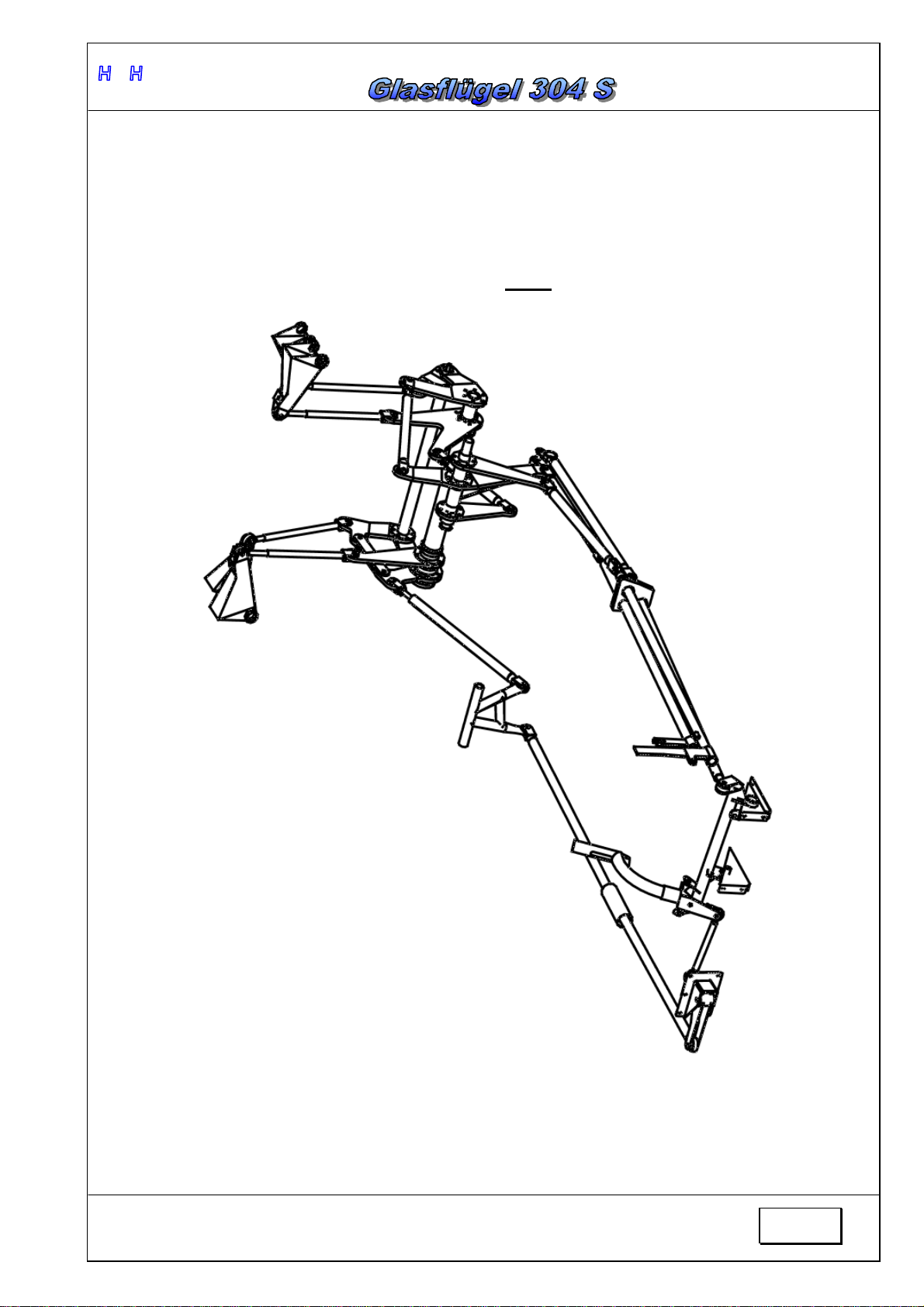
Control systems in the fuselage ............................................................................................1-3
1.3.2
Control systems in the wing..................................................................................................1-4
1.3.3
Rudder control system..........................................................................................................1-5
1.3.4
Main landing gear system.....................................................................................................1-6
1.3.5
Control surface deflections and dimensions ...........................................................................1-7
1.3.6
Electric system ....................................................................................................................1-8
2.
HANGARING, TRANSPORT, RIGGING..................................................................................2-0
2.1.1
Hangaring, Parking, and Ground Handling.............................................................................2-1
2.2
R
IGGING
.................................................................................................................................2-2
2.3
D
E
-
RIGGING
.............................................................................................................................2-3
3.
MAINTENANCE.....................................................................................................................3-0
3.1
M
ANDATORY
M
AINTENANCE
.......................................................................................................3-1
3.2
R
EGULAR
M
AINTENANCE
...........................................................................................................3-2
3.3
S
PECIAL
I
NSPECTION
P
ROCEDURE
..............................................................................................3-4
3.3.1
After hard landing and ground loops......................................................................................3-4
3.4
F
REE
P
LAY IN THE
C
ONTROL
C
IRCUITS
........................................................................................3-5
3.5
F
REE
P
LAY IN
W
ING AND
T
AIL PLANE
A
TTACHMENTS
......................................................................3-6
3.6
P
RIMARY AND SECONDARY STRUCTURES
......................................................................................3-6
3.7
D
AMAGE
.................................................................................................................................3-6
3.8
R
EPAIRS
.................................................................................................................................3-7
3.9
R
EMOVALAND
R
E
-I
NSTALLATION OF
R
ELEASES
.............................................................................3-8
3.10
C
ONTROL
S
URFACE
M
OMENTS
...................................................................................................3-9
3.11
P
LACARDS AND MARKINGS IN THE
C
OCKPIT
.................................................................................3-10
3.12
C
LEANING AND CARE
...............................................................................................................3-11
3.13
L
UBRICATIONSCHEME
.............................................................................................................3-12
3.14
T
IGHTENING
T
ORQUE
M
OMENTS
T
ABLE
.....................................................................................3-13
3.15
S
AFETY
H
ARNESS
..................................................................................................................3-13
3.16
P
ITOT AND
S
TATIC
L
INES AND
I
NSTRUMENT
C
ONNECTIONS
...........................................................3-14
3.17
L
IST OF INSTRUMENTS
.............................................................................................................3-15
3.17.1
Airspeed Indicators.........................................................................................................3-15
3.17.2
Altimeters.......................................................................................................................3-15
3.17.3
Variometers....................................................................................................................3-15
3.17.4
Magnetic Compasses......................................................................................................3-15
3.17.5
Turn and Bank Indicators ................................................................................................3-15
3.17.6
COMM...........................................................................................................................3-16
3.17.7
Transponders.................................................................................................................3-16
3.18
O
XYGENSYSTEM
....................................................................................................................3-17
3.19
S
ERVICE INSTRUCTIONS
..........................................................................................................3-17
3.20
L
IST OF SPECIAL TOOLS
...........................................................................................................3-17
4.
AIRWORTHINESS LIMITATIONS...........................................................................................4-0

T
Te
ec
ch
hn
ni
ic
ca
al
l
D
De
es
sc
cr
ri
ip
pt
ti
io
on
n,
,
O
Op
pe
er
ra
at
ti
in
ng
g,
,
M
Ma
ai
in
nt
te
en
na
an
nc
ce
e
a
an
nd
d
R
Re
ep
pa
ai
ir
r
M
Ma
an
nu
ua
al
l
Document No.: 304S/MM
Date of Issue: 08/14
iii
H
P
H
Ltd.
4.1
G
ENERAL
................................................................................................................................4-1
4.2
S
ERVICE
T
IME
..........................................................................................................................4-1
4.3
INSPECTIONS.......................................................................................................................4-1
4.4
CHECK
OUT
PROGRAM........................................................................................................4-1
4.5
INSPECTION
RESULTS..........................................................C
HYBA
!
Z
ÁLOŽKA NENÍ DEFINOVÁNA
.
4.6
OBLIGATORY
INSPECTIONS ................................................................................................4-2
4.7
L
IFE
L
IMITED
C
OMPONENT
S
ECTION
............................................................................................4-2
5.
CENTER OF GRAVITY ..........................................................................................................5-0
5.1
C
ENTER OF
G
RAVITY POSITION
...................................................................................................5-1
5.2
P
AYLOAD
R
ANGE
......................................................................................................................5-3
6.
INSTRUCTIONS FOR REPAIRS.............................................................................................6-0
6.1
CHECKLIST...........................................................................................................................6-1
6.1.1
General ...............................................................................................................................6-1
6.1.2
WING..................................................................................................................................6-1
6.1.3
FUSELAGE .........................................................................................................................6-2
6.2
S
TRUCTURE OF
C
OMPONENTS
....................................................................................................6-3
6.3
MATERIALS ..........................................................................................................................6-4
6.4
T
YPE OF WAVES
.......................................................................................................................6-5
6.5
B
ASIC
T
ECHNIQUES AND
T
OOLS
.................................................................................................6-6
6.5.1
Fiberglass-Hard foam-Sandwich Skin....................................................................................6-6
6.5.2
SOLID FIBERGLASS SKIN REPAIR...................................................................................6-12
6.5.3
Paint Job :.........................................................................................................................6-13
6.5.4
Extra Equipment ................................................................................................................6-14
6.5.5
Tools.................................................................................................................................6-15
7.
INSERTED SUPPLEMENTS...................................................................................................7-0

T
Te
ec
ch
hn
ni
ic
ca
al
l
D
De
es
sc
cr
ri
ip
pt
ti
io
on
n,
,
O
Op
pe
er
ra
at
ti
in
ng
g,
,
M
Ma
ai
in
nt
te
en
na
an
nc
ce
e
a
an
nd
d
R
Re
ep
pa
ai
ir
r
M
Ma
an
nu
ua
al
l
Document No.: 304S/MM
Date of Issue: 08/14
iv
H
P
H
Ltd.
0.1 List of Effective Pages
Section Page Date Section Page Date Section Page Date
Cover page
4
4
-
0
08/14
7
7
-
0
08/14
4
-
1
08/14
7
-
1
08/14
i
08/14
4
-
2
08/14
ii
08/14
iii
08/14
iv
08/14
v
08/14
5
5
-
0
08/14
5
-
1
08/14
1
1
-
0
08/14
5
-
2
08/14
1
-
1
08/14
5
-
3
08/14
1
-
2
08/14
1
-
3
08/14
1
-
4
08/14
1
-
5
08/14
6
6
-
0
08/14
1
-
6
08/14
6
-
1
08/14
1
-
7
08/14
6
-
2
08/14
1
-
8
08/14
6
-
3
08/14
6
-
4
08/14
2
2
-
0
08/14
6
-
5
08/14
2
-
1
08/14
6
-
6
08/14
2
-
2
08/14
6
-
7
08/14
2
-
3
08/14
6
-
8
08/14
6
-
9
08/14
3
3
-
0
08/14
6
-
10
08/14
3
-
1
08/14
6
-
11
08/14
3
-
2
08/14
6
-
12
08/14
3
-
3
08/14
6
-
13
08/14
3
-
4
08/14
6
-
14
08/14
3
-
5
08/14
6
-
15
08/14
3
-
6
08/14
3
-
7
08/14
3
-
8
08/14
3
-
9
08/14
3
-
10
08/14
3
-
11
08/14
3
-
12
08/14
3
-
13
08/14
3
-
14
08/14
3
-
1
5
08/14
3
-
1
6
08/14
3
-
1
7
08/14

T
Te
ec
ch
hn
ni
ic
ca
al
l
D
De
es
sc
cr
ri
ip
pt
ti
io
on
n,
,
O
Op
pe
er
ra
at
ti
in
ng
g,
,
M
Ma
ai
in
nt
te
en
na
an
nc
ce
e
a
an
nd
d
R
Re
ep
pa
ai
ir
r
M
Ma
an
nu
ua
al
l
Document No.: 304S/MM
Date of Issue: 08/14
v
H
P
H
Ltd.
0.2 Record of revisions
Any revision of this Manual must be recorded in the following table and in case
of approved Sections endorsed by the responsible airworthiness authority.
The new or amended text in the revised page will be indicated by a black
vertical line in the left hand margin, and the Revision No. and the date will be
shown onthe bottom left hand of the page.
Rev.
No.: Affected
Section Affected
Page Date of
Issue Approval
Date of
approval
Date
Inserted
Signature

T
Te
ec
ch
hn
ni
ic
ca
al
l
D
De
es
sc
cr
ri
ip
pt
ti
io
on
n,
,
O
Op
pe
er
ra
at
ti
in
ng
g,
,
M
Ma
ai
in
nt
te
en
na
an
nc
ce
e
a
an
nd
d
R
Re
ep
pa
ai
ir
r
M
Ma
an
nu
ua
al
l
Document No.: 304S/MM
Date of Issue: 08/14
1-0
H
P
H
Ltd.
1
1.
.
B
BA
AS
SI
IC
C
T
TE
EC
CH
HN
NI
IC
CA
AL
L
D
DA
AT
TA
A

T
Te
ec
ch
hn
ni
ic
ca
al
l
D
De
es
sc
cr
ri
ip
pt
ti
io
on
n,
,
O
Op
pe
er
ra
at
ti
in
ng
g,
,
M
Ma
ai
in
nt
te
en
na
an
nc
ce
e
a
an
nd
d
R
Re
ep
pa
ai
ir
r
M
Ma
an
nu
ua
al
l
Document No.: 304S/MM
Date of Issue: 08/14
1-1
H
P
H
Ltd.
1.1 Basic Technical data
Wing
Span....................... 18 m................... 59.06 ft
Wing area.............. 11.8m
2
............... 127.01 ft
2
Aspect ratio........... 27.43
Fuselage
Length.................... 6.79 m ............... 22.28 ft
Width...................... 0.62 m ............... 2.03 ft
Height .................... 1.48 m ............... 4.86 ft
Cockpit height....... 0.83 m ............... 2.72 ft
Horizontal Tail Unit
Span....................... 2.5 m.................. 6.89 ft
Area....................... 0.99 m
2
.............. 10.66 ft
2
Aspect ratio........... 6.33
Vertical Tail Unit
Height .................... 1.25 m ............... 3.77 ft
Area....................... 1.05 m
2
.............. 9.58 ft
2
Aspect ratio........... 1.52
Landing gear
Main wheel................... ..................5,00x5
Tail wheel..................... ..............210x65

T
Te
ec
ch
hn
ni
ic
ca
al
l
D
De
es
sc
cr
ri
ip
pt
ti
io
on
n,
,
O
Op
pe
er
ra
at
ti
in
ng
g,
,
M
Ma
ai
in
nt
te
en
na
an
nc
ce
e
a
an
nd
d
R
Re
ep
pa
ai
ir
r
M
Ma
an
nu
ua
al
l
Document No.: 304S/MM
Date of Issue: 08/14
1-2
H
P
H
Ltd.
1.2 Technical Description
The GLASFLÜGEL 304 S is single seat 18m flapped sailplane of 18m FAI
class, constructed from fiber-reinforced plastics (FRP), featuring camber-
changing flaps and a T-tail (with fixed horizontal stabilizer and elevator)
1.2.1 Fuselage
The fuselage tapers behind the wing, the faired-in one piece canopy is hinged
forward. Canopy jettisonmechanism incorporates the Rögger pivot hook.
The fuselage shell is pure CFRP shell reinforced with Carbon Aramid hybrid
fabrics in the pilot area, therefore capable of large energy absorption. The pilot
is seated in a semi-reclining position. The landing gear is retractable and
damped.
A C.G. release is fitted as standard, and an aerotow nose release can be fitted
on request.
1.2.2 Wing
The four-piece wing is cantilever and double trapezoidal. Removable wing
extensions are optional. It is constructed as a CFRP-Foam-Sandwich shell with
extruded spar caps of parallel carbon fibers and shear webs of reinforced
GFRP-Foam-Sandwich. Airbrakes are of the Schempp-Hirth type. Two integral
water ballast tanks carry a total volume of 194 liters (aprox. 42 UKgal, 51
USgal).
1.2.3 HorizontalTail Unit
The horizontal tailplane has a stabilizer and elevators. Trimming is by means of
a spring on the control drive. The stabilizer is of GFRP-Foam-Sandwich
construction.
1.2.4 VerticalTail Unit
The fin is similar to the stabilizer of GFRP-Foam-Sandwich Shell construction.
The rudder is of the CFRP construction.
1.2.5 Water ballast system
The water ballast system is controlled by a lever on the starboard side of the
cockpit. A Bowden cable connects the operating lever in the cockpit to a
torsional drive (in the fuselage center) which, on rigging the wing panels,
automatically hooks up to torque tubes actuating the ring tank dump valves.
These tubes are rotated to their "closed" position by spring force.
The operating lever in the cockpit runs over a half circle and the opening of the
valves can be locked in the each position from closed to fully opened positions.
The operating lever also drives the valve of the drainable tail ballast tank.
The tanks are located in the wings and have a total volume of 194l (aprox. 42
UKgal, 51 USgal). The ballast tanks are integral, each wing tank is divided into
2 sections located in lead space of the wings.

T
Te
ec
ch
hn
ni
ic
ca
al
l
D
De
es
sc
cr
ri
ip
pt
ti
io
on
n,
,
O
Op
pe
er
ra
at
ti
in
ng
g,
,
M
Ma
ai
in
nt
te
en
na
an
nc
ce
e
a
an
nd
d
R
Re
ep
pa
ai
ir
r
M
Ma
an
nu
ua
al
l
Document No.: 304S/MM
Date of Issue: 08/14
1-3
H
P
H
Ltd.
1.3 Sailplane systems
1.3.1 Control systems in the fuselage
Elevator, ailerons, and air brakes control systems inthe fuselage
FIG.1

T
Te
ec
ch
hn
ni
ic
ca
al
l
D
De
es
sc
cr
ri
ip
pt
ti
io
on
n,
,
O
Op
pe
er
ra
at
ti
in
ng
g,
,
M
Ma
ai
in
nt
te
en
na
an
nc
ce
e
a
an
nd
d
R
Re
ep
pa
ai
ir
r
M
Ma
an
nu
ua
al
l
Document No.: 304S/MM
Date of Issue: 08/14
1-4
H
P
H
Ltd.
1.3.2 Control systems in the wing
Ailerons and air brakes control systems in the wing
FIG. 2

T
Te
ec
ch
hn
ni
ic
ca
al
l
D
De
es
sc
cr
ri
ip
pt
ti
io
on
n,
,
O
Op
pe
er
ra
at
ti
in
ng
g,
,
M
Ma
ai
in
nt
te
en
na
an
nc
ce
e
a
an
nd
d
R
Re
ep
pa
ai
ir
r
M
Ma
an
nu
ua
al
l
Document No.: 304S/MM
Date of Issue: 08/14
1-5
H
P
H
Ltd.
1.3.3 Rudder controlsystem
FIG. 3

T
Te
ec
ch
hn
ni
ic
ca
al
l
D
De
es
sc
cr
ri
ip
pt
ti
io
on
n,
,
O
Op
pe
er
ra
at
ti
in
ng
g,
,
M
Ma
ai
in
nt
te
en
na
an
nc
ce
e
a
an
nd
d
R
Re
ep
pa
ai
ir
r
M
Ma
an
nu
ua
al
l
Document No.: 304S/MM
Date of Issue: 08/14
1-6
H
P
H
Ltd.
1.3.4 Main landing gear system
FIG. 4

T
Te
ec
ch
hn
ni
ic
ca
al
l
D
De
es
sc
cr
ri
ip
pt
ti
io
on
n,
,
O
Op
pe
er
ra
at
ti
in
ng
g,
,
M
Ma
ai
in
nt
te
en
na
an
nc
ce
e
a
an
nd
d
R
Re
ep
pa
ai
ir
r
M
Ma
an
nu
ua
al
l
Document No.: 304S/MM
Date of Issue: 08/14
1-7
H
P
H
Ltd.
1.3.5 Control surface deflections and dimensions
FIG. 5

T
Te
ec
ch
hn
ni
ic
ca
al
l
D
De
es
sc
cr
ri
ip
pt
ti
io
on
n,
,
O
Op
pe
er
ra
at
ti
in
ng
g,
,
M
Ma
ai
in
nt
te
en
na
an
nc
ce
e
a
an
nd
d
R
Re
ep
pa
ai
ir
r
M
Ma
an
nu
ua
al
l
Document No.: 304S/MM
Date of Issue: 08/14
1-8
H
P
H
Ltd.
Table of control surfaces deflections and tolerances
Control surface
Deflection
Tolerance
Rudder 25° left ±2°
25° right ±2°
Elevator 18° up ±2°
18° down ±2°
Inner flaperon 30° up ±2°
20° down ±2°
Middle flaperon 30° up ±2°
17° down ±2°
Outer flaperon 14°up ±1,5°
1.3.6 Electric system
MAIN PARTS:
-batteries
-wiring
- switches
-fuses
BATTERIES
The whole system is supplied withbattery whichis placed under a cabin floor under
the instrument panel. Itis classicalPb battery 12V/22Ah. The batterycontainment is
covered witha lid and is accessible after pressing and turning the metal knob. This
battery supplies all board instruments.
Recharging of batteries must be performed outside the glider. Adequate recharging
equipment according battery type should be used to ensure proper function and
maximal life time of batteries.
MAKE SURE THE BATTERYS ARE FULLYLOADED BEFORE FLIGHT!
FUSES AND WIRING
Eachbatteryis equipped with a fuse of adequate capacity .All instruments are
connected withbattery through the mainswitch which enables ready disconnection of
electric power from the main bus. Every individual electric instrument is equipped with
fuse of adequate capacity. All switches and fuses are placed in the instrument panel to
enable easy access of the pilot.

T
Te
ec
ch
hn
ni
ic
ca
al
l
D
De
es
sc
cr
ri
ip
pt
ti
io
on
n,
,
O
Op
pe
er
ra
at
ti
in
ng
g,
,
M
Ma
ai
in
nt
te
en
na
an
nc
ce
e
a
an
nd
d
R
Re
ep
pa
ai
ir
r
M
Ma
an
nu
ua
al
l
Document No.: 304S/MM
Date of Issue: 08/14
1-9
H
P
H
Ltd.

T
Te
ec
ch
hn
ni
ic
ca
al
l
D
De
es
sc
cr
ri
ip
pt
ti
io
on
n,
,
O
Op
pe
er
ra
at
ti
in
ng
g,
,
M
Ma
ai
in
nt
te
en
na
an
nc
ce
e
a
an
nd
d
R
Re
ep
pa
ai
ir
r
M
Ma
an
nu
ua
al
l
Document No.: 304S/MM
Date of Issue: 08/14
2-0
H
P
H
Ltd.
2
2.
.
H
HA
AN
NG
GA
AR
RI
IN
NG
G,
,
T
TR
RA
AN
NS
SP
PO
OR
RT
T,
,
R
RI
IG
GG
GI
IN
NG
G

T
Te
ec
ch
hn
ni
ic
ca
al
l
D
De
es
sc
cr
ri
ip
pt
ti
io
on
n,
,
O
Op
pe
er
ra
at
ti
in
ng
g,
,
M
Ma
ai
in
nt
te
en
na
an
nc
ce
e
a
an
nd
d
R
Re
ep
pa
ai
ir
r
M
Ma
an
nu
ua
al
l
Document No.: 304S/MM
Date of Issue: 08/14
2-1
H
P
H
Ltd.
2.1.1 Hangaring, Parking, and Ground Handling
The sailplane should only be stored or parked in well ventilated areas. Closed
trailers should be equipped with sufficiently large ventilation. Always store with
empty water tanks.
Take note to store the sailplane without stresses. This is particularly important
at higher temperatures.
Because of their slim shape, it is particularly important to store the wings
correctly. They should be stored with the L.E. pointing downwards and
supported under the wing root spar at approx. 2.4 m (7.9 ft) from the wingtip, in
a profile true wing sling.
Fuselage is correctly stored in a wide fuselage molding in front of the C.G.
release, and supported by the tail wheel.
The Tailplane is stored in two profile true slings, separated 1.5-2m (5 -6.6 ft.),
and with the L.E. pointing downward.
Under no circumstances attach the tailplane into the trailer by using the
tailplane mainattachment fittings.
Sailplanes which stay rigged for the whole year or longer periods, should be
attended to, so that rigging elements on the fuselage, wing and tailplane do not
corrode.
Dust covers should be used and are highlyrecommended.
The sailplane should not be parked in the open with the canopy in the open
position, as this may act as a concave mirror, and depending on direction of
sun-radiation, constitutes a fire hazard.
A tail dolly should always be used for ground-handling this sailplane, to prevent
unnecessary vibration of the tailplane, and stresses and wear to its attachment
fittings.
When ground-handling, do not push at wingtips, but rather close to the
fuselage.

T
Te
ec
ch
hn
ni
ic
ca
al
l
D
De
es
sc
cr
ri
ip
pt
ti
io
on
n,
,
O
Op
pe
er
ra
at
ti
in
ng
g,
,
M
Ma
ai
in
nt
te
en
na
an
nc
ce
e
a
an
nd
d
R
Re
ep
pa
ai
ir
r
M
Ma
an
nu
ua
al
l
Document No.: 304S/MM
Date of Issue: 08/14
2-2
H
P
H
Ltd.
2.2 Rigging
1. Cleanand grease pins and bearings.
2. In the cockpit, the flap lever is set at high speed, the brake lever in the
medium position, and the water ballast lever set in the closed position.
3. First rig Port wing, temporarily lock with the main pin byengaging it only
into the front spar fork bush.
Payattention that the bellcranks on the root rib are intheir neutral position
and are actuallyengaging into the opposing socket fittings on the fuselage.
4. Rig Starboard wing with the same lever settings as Port wing, and pull
together withrigging tool.
Ensure correct engagement of control as with Port wing.
5. Momentarily remove main wing spar pin. Level main pinbushes by moving
wintips up and down. Whenbushes line up push pin in and lock.
6. Rig both wing extensions. Inset and lock pins of the wingextensions.
7. Check aileronand airbrake functions.
8. Push tailplane onto the rigging - drive pins and pull out front connectionpin
with tool, push tailplane L.E. downand push front connectionpinfully into
position, remove tool. Check that the elevator rigging-drive pins are actually
correctly engaged into their opposing elevator fittings (move elevator).
9. Tape off gaps.

T
Te
ec
ch
hn
ni
ic
ca
al
l
D
De
es
sc
cr
ri
ip
pt
ti
io
on
n,
,
O
Op
pe
er
ra
at
ti
in
ng
g,
,
M
Ma
ai
in
nt
te
en
na
an
nc
ce
e
a
an
nd
d
R
Re
ep
pa
ai
ir
r
M
Ma
an
nu
ua
al
l
Document No.: 304S/MM
Date of Issue: 08/14
2-3
H
P
H
Ltd.
2.3 De-rigging
1. Pull front tailplane connection pinout, with the help of the tool, and lift up
tailplane.
2. Unlock and remove connecting pins of the wingextensions and apply the
hand force to take the wingextensionout of the wingtip .
3. Lift wingtips and remove mainpin.
4. With the help of the rigging tool, or by pulling on the wingtips, separate the
wings from the fuselage.
Other manuals for Glasflugel 304S
2
Table of contents
Other HPH Aircraft manuals